1
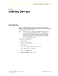
HVAC PRO for Windows User’s Manual 637.5 OEM Section Technical Bulletin Issue Date 0996 York 25-Ton VAV Rooftop Unit Introduction • Page 3 Overview *3 Configuration 5 Sequence of Operation 7 • Modes of Operation *7 • Vent/Purge Mode *9 • Heating *9 • Cooling *9 • Economizer *9 • Power Exhaust Control • Static Pressure/ Fan Control • Safety Features *10 • System Monitor *11 • Commissioning 11 *10 10 * Indicates those sections where changes have occurred since the last printing. © 1996 Johnson Controls, Inc. Code No. LIT-6375230 1 2 OEM—York 25-Ton VAV Rooftop Unit Introduction Overview The 25-ton Variable Air Volume (VAV) Controller is a special version of the VAV Controller. This special version created for York® maintains a constant discharge air temperature during Occupied mode, and maintains duct static pressure in order to control each zone temperature. An optional economizer and three stages of mechanical cooling are used for occupied temperature control. Heating operates only during the Unoccupied mode or the Morning Warmup mode. Onboard diagnostics determine if there is a mechanical problem with a stage of cooling or heating, and initiates an alarm on the system monitor notifying the service technician of the problem. The mechanical cooling and heating also lock out based on outdoor air temperature. When the supply fan starts, the inlet guide vanes are closed. In the Cooling mode, the guide vanes modulate open to meet the duct static pressure requirements. In the Heating mode, the inlet guide vanes drive full open regardless of duct static pressure. The supply fan also has proof-of-flow logic, which shuts down the unit and initiates a fan alarm if airflow is lost during normal operations. OEM—York 25-Ton VAV Rooftop Unit 3 4 OEM—York 25-Ton VAV Rooftop Unit Configuration The York 25-ton VAV Rooftop Controller comes factory configured. The configuration can be accessed by responding to a programmed sequence of questions using the HVAC PRO for Windows software tool. Select File, New, OEM, York VAV Rooftop Load York VAV Rooftop path? No Yes No response, end Q and A Factory-loaded parameters for York VAV Rooftop Application displays on screen. Stop YORKFLO Figure 1: HVAC PRO for Windows Configuration Chart OEM—York 25-Ton VAV Rooftop Unit 5 6 OEM—York 25-Ton VAV Rooftop Unit Sequence of Operation Modes of Operation Occupied Mode The unit digital controller accepts a closed contact across a binary input (BI-1) to signal the Occupied mode. The supply fan runs continuously. The inlet guide vanes modulate to provide the static pressure setpoint. The unit controls at all occupied temperature setpoints after a four minute startup delay to allow duct static pressure stabilization. The temperature setpoints are satisfied by modulating the economizer, if installed, and staging mechanical cooling as required. Heating is locked out during Occupied mode. Occupied Status (on/off) is indicated via the system monitor. Unoccupied Mode When the occupied binary input signal is broken, the unit transitions to the Unoccupied mode. The controller shuts off all mechanical cooling and the supply fan. The inlet guide vanes and economizer dampers, if used, close. The unit provides heat only if the zone temperature drops below the unoccupied setpoint (factory set at 60°F), and provides cooling only if the zone temperature rises above the unoccupied cooling setpoint (factory set at 82°F). These setpoints can be adjusted in the field using the system monitor. Upon a call for heat, the supply fan starts, the inlet vanes drive to 100% open, the zone VAV dampers open, and heating runs until the setpoint is satisfied. When there is a call for cooling, the supply fan starts, the inlet vanes modulate to meet the static pressure setpoint, the zone VAV dampers open, and the unit operates in Cooling mode until the setpoint is satisfied. OEM—York 25-Ton VAV Rooftop Unit 7 Morning Warmup/ Cooldown Mode This mode is initiated when the system is changing from Unoccupied to Occupied mode. The unit controls all warmup/cooldown temperature setpoints after a ten minute startup delay to allow duct static pressure stabilization. If the zone temperature is below the morning warmup setpoint (factory set at 65°F), the supply fan starts, the inlet vanes drive up to 100% open, the zone VAV dampers open, and heating runs until the morning warmup setpoint is satisfied. At this time, the unit transitions to Normal Occupied mode where heating is locked out. If the zone temperature is above the cooldown setpoint (factory set at 90°F), the supply fan starts, the inlet vanes modulate to meet the static pressure setpoint, the zone VAV dampers open, and economizer dampers remain closed until cooldown setpoint is achieved; then the unit transitions to Normal Occupied mode. The Morning Warmup/Cooldown mode has a maximum runtime of 60 minutes. If this time is exceeded, the unit automatically transitions to Occupied mode. Note: If the zone temperature is between the warmup and cooldown setpoints, the unit goes directly into the Occupied mode. Restart Mode Whenever power is applied to the controller, the Restart mode is initiated. This mode essentially shuts down the controller for a specific amount of time. The Restart Delay time is factory set for one minute. Restart status (on/off) is indicated via the system monitor. Shutdown Mode Any of the following conditions put the controller into the Shutdown mode: • Airflow status is not present within two minutes upon unit startup. • Airflow status is lost for more than 40 seconds during typical operation. • Shutdown command is issued from a networked Metasys® Facility Management System (FMS). During Shutdown mode, all outputs (AOs and BOs), except supply fan, are commanded off regardless of minimum on timers. This mode does not affect any occupied or unoccupied setpoints. Note: The supply fan will continue to run for five minutes after initiation of a Shutdown mode, via the FMS, to provide protection to the mechanical equipment. 8 OEM—York 25-Ton VAV Rooftop Unit Vent/Purge Mode The Vent and Purge modes open the outdoor air damper to 100% when the controller commands it to on. The supply fan is on during both modes, all mechanical heating and cooling modes are de-energized (subject to the minimum on timers). If the Vent and Purge modes are on simultaneously, Vent mode takes priority. Heating The unit has the option for either gas or electric staged heat. The factory installs either, based on the customer request. Heating operates only during Unoccupied or Morning Warmup modes and it is locked out during Occupied mode, or based on outdoor air temperature. The outdoor air temperature heating lockout setpoint is factory set to 55°F but can be adjusted from 50 to 70°F using the system monitor. Cooling The unit maintains a constant discharge air temperature. Three stages of mechanical cooling are sequenced as required to maintain the discharge air setpoint. The discharge air setpoint potentiometer is factory mounted. It may, however, be remotely mounted in the field. If the setpoint potentiometer is removed or becomes unreliable, the controller automatically uses the default setpoint. The default discharge air setpoint is factory set at 55°F, but is field adjustable from 50 to 65°F using the system monitor. Mechanical cooling and heating are locked out based on outdoor air temperature. The cooling lockout setpoint is factory set to 40°F, but can be adjusted in the field from 20 to 60°F using the system monitor. A two minute minimum on time, a five minute minimum off time, and two minute interstage delay are provided for compressor protection with a maximum of six cycles per hour per compressor. Economizer Economizer control is a factory installed option. If the unit comes equipped with an economizer section, it provides the first stage of cooling if the outdoor air is suitable. Either an optional outdoor air enthalpy controller or a separate dry bulb temperature input can be used to enable the economizer. Dual enthalpy is also available. The enthalpy controller closes a binary input (BI-2) on the controller, allowing the economizer strategy to work. The dry bulb strategy uses an economizer dry bulb setpoint (factory set at 50°F), and is field adjustable from 45 to 65°F using the system monitor. The minimum position is factory set to 15%, but is also field adjustable via the system monitor from 0 to 100% open. If the outdoor air is not suitable for free cooling, the first stage of cooling is mechanical cooling. OEM—York 25-Ton VAV Rooftop Unit 9 Power Exhaust Control The power exhaust option operates based on the economizer command output. The power exhaust control strategy energizes a binary output (BO-4) when the economizer command is at 30%, and shuts off when the command falls below 20%. Static Pressure/ Fan Control Duct static increases and decreases as each zone damper modulates to maintain temperature. The factory-provided, field-installed static pressure sensor provides the controller the main input used to modulate the inlet guide vanes, and thus maintain the static pressure setpoint. The static pressure setpoint potentiometer (AI-6) is factory mounted, but may be remotely mounted in the field. If the setpoint potentiometer is removed or becomes unreliable, the controller automatically uses the default setpoint. The default static pressure setpoint is factory set to 1.0 inch WG, but is field adjustable from 0.5 to 3.0 inches WG via the system monitor. Safety Features Air Proving In addition to the standard compressor lockout safety circuit, the 25-ton VAV controller offers air proving and high static safety controls. Before any heating, cooling, or economizer strategies are performed, airflow must first be proven. If airflow is lost for more than 15 seconds after being proven, the controller shuts down the heating or cooling system, and shuts off the supply fan after a 40 second time delay. Heating/Cooling Diagnostics The controller is able to recognize unresponsive heating or cooling systems. Each stage of heating or cooling is monitored by the discharge air sensor. Upon a call for heating or cooling, the controller tracks the discharge air temperature. If the discharge air temperature does not rise by 2°F for heat, or fall by 2°F for cooling, within ten minutes, the controller initiates a general heating or cooling diagnostic alarm via the Metasys System or the system monitor. The general alarm does not identify exactly which stage of heating or cooling has failed. 10 OEM—York 25-Ton VAV Rooftop Unit System Monitor The system monitor is an optional accessory. It is a hand-held or wall-mounted device that monitors 18 analog values, 18 binary values. It allows setpoint adjustment, indicates which value, if any, is in alarm, and flashes a red alarm LED upon any alarm state. This alerts the service technician of a problem compressor, heating stage, or fan belt problem. The following setpoints can be changed via the system monitor: • default discharge air temperature setpoint* • default duct static pressure setpoint* • OA cooling lockout setpoint • OA heating lockout setpoint • economizer dry bulb setpoint • economizer minimum position • economizer prop band • unoccupied heating setpoint • unoccupied cooling setpoint • warmup setpoint *Adjustable via system monitor only if unit-mounted potentiometer is removed or becomes unreliable. Commissioning The York 25-ton VAV Rooftop Controller is commissioned with HVAC PRO for Windows Release 5.10 or greater. The parameters are factory loaded. OEM—York 25-Ton VAV Rooftop Unit 11 Notes Controls Group 507 E. Michigan Street P.O. Box 423 Milwaukee, WI 53201 12 OEM—York 25-Ton VAV Rooftop Unit FAN 637.5 HVAC PRO for Windows User’s Manual Release 6.00 Printed in U.S.A.