1
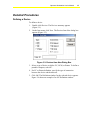
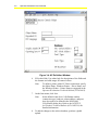
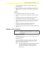
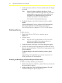
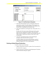
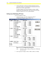
Operator Workstation User’s Manual
3-1
Chapter 3
Defining Devices
Introduction
Devices include NCMs, OWSs (PCs or portable computers), and
printers. Each network has a system called Devices, which contains all
the defined devices in the network.
Note:
N2 devices (for example, DCM, XBN, XRL), S2 devices
(for example, FPU, DSC8500), L2 devices (DSC), and
N2E devices (for example, DX91ECH) are considered
hardware objects. Refer to the Defining Objects chapter
(LIT-120149) of this manual.
This chapter describes how to:
•
define a device
•
modify a device definition
•
delete a device
•
define and modify a default report destination
•
delete a default report destination
•
set up or modify PC ports
•
modify the IP address of a device
© November 1, 2001 Johnson Controls, Inc.
Code No. LIT-120145
www.johnsoncontrols.com
3-2
Operator Workstation User’s Manual
Key Concepts
Devices Summary
Use the Devices summary to view devices, delete devices, and access
device Focus and Definition windows. Figure 3-1 shows an example
of a Devices summary.
Figure 3-1: Devices Summary
Table 3-1 describes the information that each field in the Devices
summary provides.
Table 3-1: Devices Summary Fields
Field
Description
Status
Status of the device: online or offline. If the device is offline, an asterisk appears. If
online, no asterisk appears
Item
Name of the device
Description
Device’s expanded ID
Operator Workstation User’s Manual
3-3
Device Focus Windows
To view or modify the definition information for a selected device, use
the Device Focus window. Figure 3-2 shows the Network Controller
(NC) Focus window.
Figure 3-2: NC Focus Window
Default Report Destination
Device Focus windows are nearly identical to Device Definition
windows. However, the Printer and PC Focus windows have
one additional field: Default Report Destination. This field displays the
currently defined default report destination. Reports are sent to this
default destination if the device is offline and unable to receive reports.
The default destination can be any defined PC, defined printer, or
PC file.
3-4
Operator Workstation User’s Manual
Internet Protocol (IP) Address
Unless a device is defined offline using DDL, its default address is
0.0.0.0. Modify the IP Address using the IP Address Configuration
summary (Figure 3-8).
Unconfigured OWSs
Unconfigured OWSs have the same functionality as defined OWSs,
except that they cannot receive change-of-state reports or archive data.
An unconfigured OWS can be NC-Direct or NC-Dial (not N1-Direct).
Unconfigured OWSs do not appear in the Devices system on the
Network Map or in the Devices summary.
To use an unconfigured OWS, make the NC-Direct or NC-Dial
connection and log on to the desired network using the Logon dialog
box. The unconfigured OWS must have the network in its database. If
the unconfigured OWS does not have the network in its database,
define the network at the undefined OWS.
Operator Workstation User’s Manual
3-5
Detailed Procedures
Defining a Device
To define a device:
1.
Double-click Devices. The Devices summary appears
(Figure 3-1).
2.
On the Item menu, click New. The Devices-Item New dialog box
appears (Figure 3-3).
Figure 3-3: Devices-Item New Dialog Box
3. Select a type of device to define: PC, NCM, or Printer. To define a
portable computer, select PC.
4. For PC or Printer definition, specify the type of connection
between the device and the network.
5. Click OK. The Definition window for the selected device appears.
Figure 3-4 shows an example of an NC Definition window.
3-6
Operator Workstation User’s Manual
Figure 3-4: NC Definition Window
6.
Fill in the fields. Use online help for descriptions of the fields and
the formats and valid ranges for entered values.
Note:
7.
On the Item menu, click Save.
Note:
8.
To define a printer with a PC-Direct connection, specify
the Object Name, Windows Printer – Driver Name, and
the Windows Printer – Printer Name as suggested in the
Operator Workstation Technical Bulletin (LIT-636013).
Items defined in the device’s Definition window
(connection type, baud rate, subnet address, and port)
may also need to be defined in the NOVRAM
View/Modify dialog box. Refer to the NCSETUP
for Windows Technical Bulletin (LIT-6360251d) for
detailed information.
To add the changes to the archive database, perform a global
upload.
Operator Workstation User’s Manual
9.
3-7
After PC definitions, compile the NET DDL database on the
newly defined PC.
10. After NCM definition, perform a global upload. Compile the NC
DDL database file, and perform a code and data download to the
NCM.
Shortcut
To copy definition information from one device to another:
1.
Select a device in the Devices summary that is similar to the new
device.
2.
For example, to define a new N1-Direct Connect PC, select an
existing N1-Direct Connect PC in the Devices summary.
3.
On the Item menu, select New. The Copy From field at the bottom
of the Definition dialog box displays the name of the selected
device.
4.
Click OK. A Definition window appears with the same
configuration as the selected N1-Direct Connect PC.
5.
Specify a unique name, make any necessary changes, and save the
new device.
Modifying a Device Definition
IMPORTANT: Changing the definition information of a PC or printer
while data is being sent to the device can result in the
loss of the data.
To modify device definition:
1.
Double-click the name of the device. The Focus window for the
selected device appears.
2.
Modify the fields.
If you are not familiar with a field, use online help. This help
includes descriptions of the fields and the formats and valid
ranges to use when entering values.
Note:
To define a printer with a PC-Direct connection, specify
the printer in the Printer Type field exactly as it is
specified in the Windows Control Panel (under the
Printers icon).
3-8
Operator Workstation User’s Manual
3.
On the Item menu, click Save. Close the window after the changes
are saved.
Note:
4.
Some of the items modified in the device’s Focus
window (such as connection type, baud rate, and subnet
and port address) may also need to be modified in the
NOVRAM View/Modify dialog box. Refer to the
NCSETUP for Windows Technical Bulletin
(LIT-6360251d) for detailed information.
To add the changes to the archive database, perform a global
upload.
After modifying an NC device, perform an NC data download,
following the guidelines described in the Uploading and
Downloading Databases chapter (LIT-120155) of this manual.
Deleting a Device
To delete a device:
1.
Double-click Devices. The Devices summary appears
(Figure 3-1).
2.
Click the device.
Note:
Only one device can be deleted at a time. The delete
option is not available if more than one device is
selected or if no devices are selected.
3.
On the Item menu, click Delete. The Delete dialog box appears.
4.
Click the OK button in the Delete dialog box to delete the device
from the operational database. The device no longer appears in the
Devices summary.
To add the changes to the archive database, perform a global
upload.
After deleting a PC (either dial-up or directly connected to an
NCM), perform an NC data download.
Defining or Modifying a Default Report Destination
To define or modify a default report destination:
1.
Double-click the name of the PC or printer. The Focus window for
the selected device appears.
2.
On the Action menu, click Add Default Destination. The Add
Destination dialog box appears (Figure 3-5).
Operator Workstation User’s Manual
3-9
Figure 3-5: Add Destination Dialog Box
3.
Select the default destination type by clicking the Printer or PC
option button or the PC file option button. The Destination list
box displays all defined printers and OWSs in the facility, or all
defined OWSs, depending on the destination type.
4.
Specify the destination by clicking the name of the printer, PC, or
PC file.
To select a PC file, first select the OWS where the file resides.
The Files list box displays all existing PC files at that OWS.
Either select an existing file, or type in a new file name in the File
Name text box. Typing a new file name creates the file at the
selected OWS.
5.
Click OK. The destination appears in the Default Report
Destination field in the Device Focus window.
To add the changes to the archive global database, perform a
global upload (described in the Uploading and Downloading
Databases chapter [LIT-120155] of this manual).
Deleting a Default Report Destination
To delete a default report destination:
1.
Double-click the name of the PC or printer. The Focus window for
the selected device appears.
2.
On the Action menu, click Delete Default Destination. The Delete
Default Destination dialog box appears.
3-10
Operator Workstation User’s Manual
3.
Click the OK button to delete the default destination from the
operational database. The Default Report Destination field in the
Device Focus window appears blank.
To add the changes to the archive database, perform a global
upload (which is described in the Uploading and Downloading
Databases chapter [LIT-120155] of this manual).
Setting Up or Modifying PC Ports
To set up or modify PC ports:
1.
On the SetUp menu, click PC Configuration. The PC
Configuration dialog box appears (Figure 3-6).
Figure 3-6: PC Configuration Dialog Box
Note:
2.
If the Device Type is Mouse or Printer, the 19200 baud
rate is not valid.
Select a port (for example, COM1, COM2, COM3, or COM4).
Operator Workstation User’s Manual
3-11
3.
Click the Device Type that corresponds to the device connected to
the selected port. COM3 and COM4 are limited to direct
connections.
4.
Click the Baud Rate that corresponds to the baud rate for the
selected port. A 19200 baud rate is valid only if the Device Type
is NC Direct or NC Dial (POTS or ISDN).
5.
Repeat Steps 3 through 5 until all ports are configured.
6.
Click OK, and reboot the PC.
Setting Up the Modem for the PC
To set up the modem for the PC:
1.
Click Modem Setup button in the PC Configuration dialog box.
The Modem Setup dialog box appears (Figure 3-7).
MODEM SETUP - PC Configuration
Modem Port
OK
COM1
COM2
Cancel
Select Modem Type Below
(Brand Names)
Modemset
Figure 3-7: Modem Setup Dialog Box
2.
Select the COM port that the modem uses.
3.
Use the Select Modem Type Below drop-down menu to select the
brand of the modem.
4.
Click OK. This operation sends the correct setup string to the
metasys.ini file.
5.
Restart Metasys software to load string into the attached modem.
3-12
Operator Workstation User’s Manual
Modifying the IP Address of a Device
To modify the IP Address of a device:
1.
On the SetUp menu, click IP Address Configuration. The
IP Address summary appears (Figure 3-8).
Figure 3-8: IP Address Summary
2.
Select the device. The device appears highlighted.
3.
On the Action menu, click Modify IP Address. The Item
Address-Modify IP Address dialog box appears (Figure 3-9).
Figure 3-9: Item Address-Modify IP Address Dialog Box
Note:
To set the IP Address to zero, select Zero IP Address in
the Action menu rather than Modify IP Address. This
automatically sets the selected device and all other
devices with the same subnet address to 0.0.0.0.
Operator Workstation User’s Manual
3-13
4.
Enter the new IP address and click OK. The new address appears
in the IP Address Configuration summary.
5.
On the System menu, click Save.
6.
Double-click the Control Menu box to close the summary.
3-14
Operator Workstation User’s Manual
Troubleshooting
Correcting Invalid Entries
If you enter invalid information into a field, the field appears red when
you attempt to select another field. In this case, select the invalid entry
and correct it. In addition, if you attempt to save invalid information, a
dialog box appears indicating the error. In this case, acknowledge the
message by clicking the OK button. Then make corrections and
attempt to save the information again.
An entry might be invalid because it is in the wrong format or exceeds
the valid range.