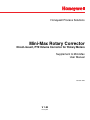
1
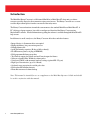
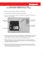
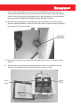
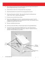
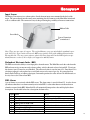
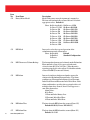
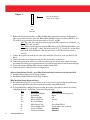
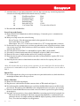
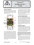
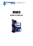
Honeywell Process Solutions
Mini-Max Rotary Corrector
Direct-mount, PTZ Volume Corrector for Rotary Meters
Supplement to Mini-Max
User Manual
October 2010
V 1.03
Honeywell
2
www.honeywell.com
Rotary Corrector
TABLE OF CONTENTS
4
Introduction .....................................................................................................................................................5
5
Installation Instructions .....................................................................................................................................6
9
Setting the instrument Parameters ...................................................................................................................10
11
Instrument Mounting Plate Identification .........................................................................................................12
13
Input Sensor ..................................................................................................................................................14
13
Redundant Electronic Index ...........................................................................................................................14
13
REI Alarms .......................................................................................................................................14
14
Live Dial Rate Display ...................................................................................................................................15
15
Differential Performance Test .........................................................................................................................16
16
Item List ........................................................................................................................................................17
17
Meter Proving ................................................................................................................................................18
Rotary Corrector
1.00
1.01
1.03
Initial Release
Revision
Revision List
Cover page
May 2003
June 2008
Honeywell update
October 2010
3
Rotary Corrector
Introduction
The Mini-Max Rotary Corrector is a full featured Mini Max (or Mini-Max AT) electronic gas volume
corrector specially adapted to direct mount to various rotary meters. The Rotary Corrector uses a sensor
to collect input volume pulses from the sensor well of the rotary meter.
The Rotary Corrector functions in much the same manner as the standard Mini-Max or Mini-Max AT. A
PC (desktop or laptop computer) is needed to configure and download the Rotary Corrector using
MasterLink32 software. Detailed information regarding the software is available through the MasterLink32
help screens.
In addition to its small, sturdy case, the Rotary Corrector offers these and other features:
• Integral design, i.e. Instrument drive not required
• High-performance, low power microprocessor
• Extended battery life
• Audit Trail memory capacity (40 days of daily or hourly)
• FLASH memory (hence, no plug-in EPROMs)
• Field programmable firmware updates
• Two Form-A outputs for Volume and one Form-A output for Alarms
• Software selectable Pulse Widths for volume pulses
• Serial port (CMOS) with automatic baud rate settings (optional RS-232 port)
• High-speed data transfers (up to 38.4 kbaud)
• On-board surge protection for serial & pulse data
• Field replaceable Alkaline batteries
• Electronic uncorrected volume backup
Note: This manual is intended for use as a supplement to the Mini-Max Operator’s Guide and should
be used in conjunction with that manual.
4
www.honeywell.com
Rotary Corrector
INSTALLATION INSTRUCTIONS OF THE
MINI-MAX ROTARY CORRECTOR (Dresser & Romet)
1. Remove the contents from the box and from the mounting kit bag.
2. Review the contents and identify each item per the parts list included.
3. Select the adapter mounting plate, four 10-32 x 2”SS flat head screws (60-1374), and four countersink star washers (20-9505).
Meter Adapter
Plate
Flathead Screws
(60-1374)
Star Washers
(20-9505)
Sensor Hub
4. Identify the proper orientation of the adapter mounting plate in relationship to the meter. Ensure the
correct mounting plate is being used for the specific kind of meter by referencing the stamping on
the plate. Ensure the threaded sensor hub is facing inside the Mini-Max enclosure.
5. Without putting undue stress on the sensor connector, thread the sensor into the mounting plate.
This can be accomplished by rotating the plate while holding the sensor, or rotating the sensor after
removing it from the clips and connector.
6. Place the spiral nylon insulator, pointed end first, in the temperature probe chamber of the meter
and cut to the required length. This will help center the probe and reduce the potential risk of stray
electrical current coming in contact with the probe.
5
Rotary Corrector
7. Place the countersink star washers on the four 10-32 x 2” screws and mount the adapter plate to
the Mini-Max using the four screws. To assure a reliable seal to the adapter plate, push the O-ring
located around the case side port against the adapter plate.
At this point the Mini-Max should be configured to mount onto the meter end.
Push O-ring
against adapter
plate
Temperature
Probe
Sensor
8. Identify the meter gasket, meter mounting screws and lockwashers.
Mounting
Screws
Meter Gasket
6
www.honeywell.com
Rotary Corrector
9. Place the meter gasket against the meter end, and attach the Mini-Max with adapter plate to the
meter using the meter mounting screws and lockwashers. Four lockwashers are provided in the kit
and they can be placed onto any of the mounting screws. Be aware that there is one meter mounting screw internal to the Mini-Max for LMMA (including 7M-16M) installations.
10. If provided, insert the temperature probe through the appropriate fitting on the adapter mounting
plate from within the Mini-Max. Position the probe to the desired location and secure by tightening
the nut using a 7/16” open-end wrench.
Temperature
Probe Fitting
11. If provided, connect the pressure tubing to the Mini-Max and then to the external pressure tap on
the meter
12.
.
Place the battery pack against the side port facing the meter, then secure with the Velcro strap.
Ensure the sensor ribbon cable is folded and condensed as much as possible.
Velcro
Strap
Battery
Pack
7
Page 8
Rotary Corrector
13.
Ensure the open end of the air vents are rotated toward the ground so to protect from entrance of
moisture. Tighten the inside nut to secure the vent in place.
14.
Connect the battery cable to J3 or J4 on the main board to start up the unit.
15.
Link to the instrument and select item 432. Choose the appropriate meter model.
16.
Select item 433 and choose “Enabled”. The sensor will now begin to read andupdate meter
volume. Choose “Prover” when proving the instrument.
17.
If desired, place item 434 in the meter reader list.
18.
Synchronize item 002 with item 434 to have a coordinated totalized uncor volume. Do this by
writing a value to item 002 that matches the reading at item 434. (Note: If all is operating correctly,
item 002 and 434 should read the same value.)
19.
Disconnect or unlink from the instrument.
20.
Check the operation of the LCD by scrolling through the display list using the MI pushbutton.
21.
Secure the front door by tightening the four Phillips head screws evenly. Ensure the door is
configured so the MI logo and the LCD are right side up. (The door is symmetrical and can be
rotated to accommodate different meter positions)
Door
Screws
MI Logo
Pushbutton
Air Vents
8
www.honeywell.com
Page 9
Rotary Corrector
Setting up the instrument Parameters
There are two item settings that must be made for the Rotary Corrector to function properly. The first is the
Meter Index Rate (Item 098) and the second is the Meter Scaling Factor (Item 114). The values at items
098 and 114 are automatically set by the firmware simply by selecting the Meter type and size at item 432.
The following two tables show the correct setting for the different meter sizes and manufacturers. For
manually setting the parameters, find the table with the correct meter manufacturer, go down the size
column to the proper size. Go across the row to the column that contains the appropriate setting of Item
114 in relation to Item 098.
Dresser LMMA Meters
Item 098=2 Item 098=3
(10 CuFt)
(100 CuFt)
Set Item 114 Set Item 114
to:
to:
Meter Size
1.5M
0.1896107 0.0189611
3M
0.3792213 0.0379221
5M
0.6321493 0.0632149
7M
1.0666667 0.1066667
11M
1.7066667 0.1706667
16M
2.5284267 0.2528427
23M
4.4791467 0.4479147
38M
8.7722667 0.8772267
56M
15.0818133 1.5081813
102M
35.7785600 3.5778560
Table 1
Dresser LMMA Meter Values
9
Rotary Corrector
Meter
Size
RM1000
RM1500
RM2000
RM3000
RM5000
RM7000
RM11000
RM16000
Romet Meters
Item 098=2 Item 098=3
(10 CuFt)
(100 CuFt)
Set Item 114 Set Item 114
to:
to:
0.1369532 0.0136953
0.1896294 0.0189629
0.2614579 0.0261458
0.3792589 0.0379259
0.6269372 0.0626937
1.0448964 0.1044896
1.6960649 0.1696065
2.4032649 0.2403265
Table 2
Romet Meter Values
10
www.honeywell.com
Rotary Corrector
Rotary Meter Mounting Plate Identification
The following pages serve as a reference to identify which instrument mounting plate adapts to which meter.
Be sure to take into account the meter manufacturer, meter series, meter size, and temperature probe
location when ordering or installing the appropriate mounting kit.
Dresser LMMA
1.5-5M,
23M-102M
Kit #20-9424
Dresser LMMA
7M-16M
Kit #20-9425
11
Rotary Corrector
Romet 1000-5000
Internal
Temperature Probe
Kit #20-9426
Romet 7000-16000
Internal
Temperature Probe
Kit #20-9427
Romet
External
Temperature
Probe
Kit #20-9477
12
www.honeywell.com
Page 13
Rotary Corrector
Input Sensor
The Rotary Corrector receives volume pulses directly from an input sensor mounted in the body of the
meter. The sensor threads into the rotary meter mounting plate and connects to the Mini-Max main board
at J2 via a ribbon cable. The connector is keyed, thus preventing the possibility of incorrect connections.
Ribbon Cable
Sensor Body
Sensor Connection
to main board
Note: There are two types of sensors. The original Rotary corrector units had the standard sensor
(p/n: 40-2910). Newer units will have the REI sensor (p/n 40-2983) with additional functionality
discussed below. The two sensor units are physically interchangeable but the REI requires an updated firmware version (2.40 or higher) to support its added features.
Redundant Electronic Index (REI)
The REI sensor has the ability to store input pulses from the meter. The Mini-Max reads the value from the
REI and converts it to an uncorrected volume reading, scaled to the units selected at item 092. To activate
this feature, item 433 must be set to Enabled. The converted value is stored at item 434. Since Item 434 is
a backup reading it is only updated on a serial link, meter read or start of gas day. It is not updated on
hourly Audit Trail logs or volume pulse inputs. In normal operation, the value of item 434 should match, or
be very close to, the value of item 002.
REI Alarms
A set of alarms are associated with the REI sensor. The alarm status is stored in Item 435. A value of zero
(0) indicates that there is no alarm currently active in the REI. A value other than zero indicates that an
alarm has occurred in the REI. MasterLink32 will automatically intepret the value and display the alarm
description. See the table below for a description of alarm codes.
Value
0
1
2
3
4
5
6
7
Alarm
None
Battery Low
Read Error
Battery Low & Read Error
Write Error
Battery Low & Write Error
Read Error & Write Error
Battery Low, Read Error & Write Error
Cause
Low Battery in the REI
Mini-Max is unable to read from the REI
Mini-Max is unable to write to the REI
13
Rotary Corrector
Live Dial Rate Display
The Rotary Corrector has the ability to display live dial rate on the LCD. This feature is enabled at Item
129. The dial rate is displayed in units of cubic foor per hour (or cubic meters per hour) and has a resolution of one tenth of a cubic foot (or one thousanth of a cubic meter). When enabled, the live dial rate can be
displayed by scrolling through the meter read list until the following screen appears.
This screen will remain for approximately three seconds before changing to the wait screen below.
The wait screen will remain anywhere from one to twenty seconds, depending on the amount of time it takes
for the Mini-Max to receive two meter volume pulses through the sensor. After receiving the two volume
pulses, the Mini-Max will calculate the flow rate and display it on the LCD. If no volume pulses are
counted in twenty seconds (approximately 1% of meter capacity), the flow rate displayed will be zero as
shown below. After 10 minutes, the display will flash TIMEOUT and return to the corrector mode.
14
www.honeywell.com
Page 15
Rotary Corrector
Differential Performance Test
The condition of a rotary meter can be measured by performing a simple test called the Differential Performance Test. This test requires that the differential pressure across the meter be measured, as well as
calculating the dial rate. Normally, calculating the dial rate can be tedious. However, with the Rotary
Corrector installed, the dial rate can be displayed via the Live Dial Rate Display. The measured values of
the dial rate and differential pressure can then be compared to intial factory data to determine if the meter is
performing within specifications. For more information, consult the meter manufacturer’s documentation.
15
Rotary Corrector
16
Item
No.
432
Item Name
Rotary Meter Model
Description
Model of the rotary meter the instrument is mounted to.
This item will automatically set Items 098 and 114 to their
appropriate values. Default=0
Select: 0=Not Applicable 10=Dresser 102M
1=Dresser 1.5M 11=Romet RM1000
2=Dresser 3M
12=Romet RM1500
3=Dresser 5M
13=Romet RM2000
4=Dresser 7M
14=Romet RM3000
5=Dresser 11M 15=Romet RM5000
6=Dresser 16M 16=Romet RM7000
7=Dresser 23M 17=Romet RM11000
8=Dresser 38M 18=Romet RM16000
9=Dresser 56M
433
REI Mode
Item used to select the type and operation of the
redundant uncorrected volume index.
Select: 0=Disabled
Default
1=Enabled
Standard Configuration
2=Prover
434
REI Uncorrected Volume Backup
Total accumulated uncorrected volume from the Redundant
Electronic Index. Item 434 is expressed in the units
selected at item 092 (Unc Vol Units). When the unit is
operating properly, the value at Item 434 should match the
value at item 002 (Uncorrected Volume).
435
REI Alarm
Item used to indicate whether an alarm has occured in
relation to the Redundant Electronic Index. The Alarm
conditions are: Electronic Index Battery Low, Electronic
Index Read Error and Electronic Index Write Error. Each
alarm condition has a specific value associated with it so if
multiple alarms have occured, Item 435 will appear as a
sum of the alarm values.
Alarm Values:
0-No Error
1-Electronic Index Battery Low
2-Electronic Index Read Error
4-Electronic Index Write Error
436
REI Alarm Time
The time when the REI Alarm first occurred (Item 435)
Default=00:00:00 (Format: HH:MM:SS)
437
REI Alarm Date
The date when the REI Alarm first occurred(Item 435)
Default: 01-01-02
www.honeywell.com
Rotary Corrector
ROTARY MINI-MAX PROVING PROCEDURE
(DOS Prover Software only)
Purpose of the Test:
This procedure describes the testing of Rotary Mini-Max accuracy of measuring gas flow through a
Roots or Romet rotary meter.
Rationale For This Procedure:
Using this approach, reasonable test times are achieved, and prover accuracy is maximized. To
accomplish this task, a special proving adapter must be used to connect the sensor to the Mini-Max. The
pulses/test and test volume values (high, medium, and low flow rates) are specified in Tables 1 & 2 of this
procedure. These two values need to be entered into the prover program. The Mini-Max will send output
pulses to the prover’s OPTO interface to start and stop the prover.
In addition, this procedure is the first version that significantly reduces the complication of meter
scaling factors for the user. When the meter model is selected, the factor is loaded into item 114 automatically for normal rotary corrector operation. When prover mode is selected, a divide by 32 is removed
internally to allow the corrector to receive pulses faster. Also, “PROVING” is put up on the LCD screen.
When the unit is later taken out of prover mode, the LCD returns to normal displaying and internal scaling
factors are returned to those that are selected by the meter model.
Equipment, Documentation, & Software Needed:
This procedure, Mercury Document, “Procedure, Rotary Mini-Max Proving”, FD-489
Model 5 Roots Prover (or equivalent)
Rotary Mini-Max
Laptop Computer
Prover Software (DOS version for the Model 5 Prover)
Mercury Master-Link Software
Mercury: Cable Assembly, Rotary Mini-Max Prover, 40-2974
Mercury: Assembly, Sensor Proving Adapter, 40-2977
Note: The last 2 items on this list may be acquired by purchasing the Rotary Mini-Max Proving Kit, 209459.
Equipment Connections:
1. Mount the meter to be tested on the test stand.
2. Screw the Sensor Probe into the rotary mounting plate, inside the Mini-Max. You may need to remove
the battery pack to do this. Route the sensor cable under the battery pack and under the hold-down
clip.
3. Mount the Rotary Mini-Max to the meter, using the bolts that are provided in the installation kit. If this
is a new instrument and the meter is being set up for field installation, follow the installation instructions,
FD-487. Note: Item values specified in FD-487 do not have to be entered at this time, since they will
be changed in this procedure.
4. If the Mini-Max is not providing temperature correction, skip to the next step. Install the Mini-Max
temperature probe into the meter’s thermowell.
5. Remove the connector end of the Rotary Sensor Probe from the main board. Plug the Sensor Proving
Adapter (male end), assembly 40-2977, into the sensor cable (it is keyed).
6. Plug the Sensor Proving Adapter (female end), assembly 40-2977, into the main board, using the
diagram below: (J2 viewed above the Mini-Max main board)
17
Rotary Corrector
Figure 1:
•
•
•
•
•
•
•
•
•
•
•
•
•
Line up missing pin
with connector plug.
2x5
connector
7. Remove the black connector that is on TB1 (the Mini-Max output pulse connector) and plug in the
same type of connector that is part of the Rotary Mini-Max Prover Cable Assembly, #40-2974. If a
TC proof is being performed, move the wire that is on YA to YB , on TB1.
Note: The color of the wires that connect to this black TB1 connector are “black on YA (YB
if using TC)“ and “red on K”.
Note: If there is further question about the TB1 wiring, get a DVM (Digital Volt Meter) and
set it on the “10 volts DC” setting. Put the red probe on YA (YB if using TC) and the black
probe on K. If the DVM reads -0.6 volts instead of 13 volts, then the wires must be
reversed.
8. Connect the opposite end of the prover cable to the small blue prover box, on the port labeled “I.D.
Pulser”.
9. Connect all of the prover temperature and pressure sensor/cables on the prover.
10. Connect the prover main airflow hose to the test stand and prover master meter. Observe all safety
precautions listed in the prover operation manual, especially keeping hands clear of the meter inlet port.
11. Connect the laptop to the Mini-Max, using the communications cable.
12. Connect the prover’s little blue box to its computer box.
Software Installations Needed: (go to Mini-Max Item Setup if software is already installed)
13. Install the Prover Software on the laptop computer.
14. Install MasterLink32 Software on the laptop computer.
Mini-Max Item Setup (Important Step!):
15. If the Mini-Max items have been previously set up, or have been set up according to special factory
specifications, upload the items and save them in an item file, using MasterLink32.
16. To get the Mini-Max configured for prover testing, these items values must be entered (or verified),
using MasterLink32: (Find Table 3 at the end of this procedure)
Item
Description
Value or Setting
432
Rotary Meter Model
Select Meter Model being tested
433
Index Mode
Prover
56
Pulser A Scaling
2.0
93
Pulser A Vol Code
UncVol
124
Revs Per Wakeup
1
98
Meter Index Code
Select From Table 3
92
Uncorr Volume Units
Use the same value as item 98
0
Corrected Volume
00000000
2
Uncorrected Volume
00000000
18
www.honeywell.com
Page 19
Rotary Corrector
17. If the Mini-Max is not providing temperature correction, skip to the next step. When using temperature
correction, the following additional items must be entered (or verified):
109
Fixed Pressure Factor
Fixed
110
Fixed Super Factor
Fixed
111
Fixed Factor Temp
Live
57
Pulser B Scaling
2.0
94
Pulser B Vol Code
CorVol
90
Corr Volume Units
Use same value as Item 98
18. Disconnect link with Mini-Max.
Prover Setup on the Laptop:
19. Remove the RS-232 communications cable from the laptop. Connect the prover’s communications
cable to the laptop.
20. In the prover setup screen, choose the following:
Prover Capacity: Select the master meter that has the appropriate flow capacity.
Test Control Mode: Set to “OPTO”
Meter Output: Set to “UC” for uncorrected volume (Set to “TC” if using temperature correction.)
21. For the next few steps, when the prover software program asks for entry of pulses/test and test volume,
a list of values is provided. If the value that you desire is not in the list, select “Enter” from the list; then
select the value desired.
22. Select the pulses/test from Table 3*, for the high flow capacity (100%), from column 2.
23. Select the test volume from that same table, for the high flow capacity (100%), from column 3.
24. Enter the 3 flow rates, for high, medium, and low flows, in the prover program.
25. Enter the pulses/test and test volume from that same table, for the medium flow capacity (50%), from
columns 4 and 5.
26. Enter the pulses/test and test volume from that same table, for the low flow capacity (10%), from
columns 6 and 7.
*Note: For a faster (but less accurate) proving operation, use the normal open flow and check flow
specifications recommended by the prover manufacturer. For guaranteed accuracy, use the values in
table 3.
Run the Test:
27. Proceed through the rest of the prover responses that are required and start the test, which should now
run the high, medium, and low flow prover tests.
Restore Mini-Max:
28. Remove the Sensor Proving Adapter.
29. Plug the sensor cable back into the black connector that is on TB1 main board (figure 1).
30. Upload the item file to the Mini-Max that was saved before the Mini-Max items were modified for the
prover needs. This will restore the Mini-Max to the configuration that it was in, prior to prover testing.
31. If desired, adjust the Mini-Max uncorrected and corrected volumes for gas that was bypassed during
the proving test.
32. If possible, it is best practice to observe that the Mini-Max is operating properly before leaving the site.
This can be done by checking all of the item codes and comparing them to a standard item report
printout for the site or by simply watching the CORVOL display registering volume (if meter not too
slow). Chose the best technique for your application.
Page 20
19
Rotary Corrector
33. Caution: If this is a new Mini-Max installation, be careful to complete the installation procedure, FD487, at this time, especially the item values (which may have been skipped earlier in this procedure).
Especially important are items 92, 98 (and other application specific items) that were changed during the
prover testing.
34. Caution: Be sure to set Index Mode (Item 433) from “Prover” to “Enabled”. This will restore the unit
to proper corrector mode and remove “Proving” from the LCD display.
Wrap-Up:
35. The prover test is now complete. The Rotary Mini-Max is ready to be used.
20
www.honeywell.com
Rotary Corrector
Meter
Size
1.5M
2M
3M
5M
7M
11M
16M
23M
38M
56M
102M
RM1000
RM1500
RM2000
RM3000
RM5000
RM7000
RM11000
RM16000
Rotary Meter Prover Configuration
Drive
Pulses
Test
Pulses
Test
Pulses
Test
Rate Per Test Volume Per Test Volume Per Test Volume
Meter
High
High
Medium Medium
Low
Low
Index
Flow
Flow
Flow
Flow
Flow
Flow
Code Capacity Capacity Capacity Capacity Capacity Capacity
(Item 98) (100%) (100%) (50%)
(50%)
(10%)
(10%)
(CF)
(CF)
(CF)
(CF)
(CF)
(CF)
(CF)
Roots Meters
10
5
50
4
40
3
30
10
5
50
4
40
3
30
10
10
100
9
90
6
60
10
16
160
13
130
10
100
10
23
230
20
200
17
170
10
35
350
30
300
26
260
100
6
600
5
500
5
500
100
8
800
7
700
7
700
100
14
1400
14
1400
14
1400
100
23
2300
23
2300
23
2300
100
55
5500
55
5500
55
5500
Romet Meters
10
3
30
3
30
2
20
10
5
50
4
40
3
30
10
6
60
5
50
4
40
10
8
80
7
70
6
60
10
15
150
12
120
10
100
10
20
200
18
180
16
160
10
34
340
30
300
26
260
10
47
470
43
430
38
380
Table 3
Meter Proving Values
21
Find Out More:
To learn more about
Mercury Instruments products, contact your
Honeywell Process Solutions representative,
visit www.mercuryinstruments.com or call
513-272-1111.
Automation and Control Solutions
Honeywell Process Solutions
3940 Virginia Ave.
Cincinnati, OH 45227
513-272-1111
www.honeywell.com
MNL-MRC-1
October 2010
© 2010 Honeywell