1
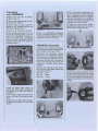
The PREMIERE turntable is essentially a synthesis of creative design, painstaking craftsmanship and advanced technological processes. The primary goal which shaped the development of the PREMIERE was an uncompromising pursuit of excellence in music reproduction. The PREMIERE represents the culmination of everything that we have learned about disc reproduction; it is an evolutionary development of our widely-acclaimed ORACLE DELPHI. But we had an important secondary goal; to provide a maximum of user-convenience without compromising the sound quality, and to engineer the product such that all music lovers could set it up to realize its full potential — not just technically proficient audiophiles. We invite your critical examination of the PREMIERE as we expand in this brochure. Marcel Riendeau President, Trans-Audio Corporation Ltd. Contents Technical Informations Philosophy and Concept 2 T h e G r o o v e : Nature and P r o b l e m s . . The P R E M I E R E Turntable 3 Record C o u p l i n g S y s t e m The Mat T h e Platter T h e Bearing The Subchassis The S u s p e n s i o n 3 3 4 4 4 5 The The The The The Motor Pulley Belt Control Unit FINALE Tonearm 6 6 6 6 7 T h e Head Shell The A r m T h e Bearings Vertical Tracking A n g l e Adjustment S y s t e m (VTA) Azimuth Adjustment System Auto-lift S y s t e m RC Compensation Box 7 7 7 7 8 8 8 U n p a c k i n g your P R E M I E R E PREMIERE Assembly Installing the Control Unit Cartridge Installation T o n e a r m Installation Cartridge A l i g n m e n t Adjusting your P R E M I E R E Fine T u n i n g your F I N A L E T o n e a r m Tracking Force A d j u s t m e n t 11 11 12 12 12 12 13 13 13 Vertical Tracking A n g l e A d j u s t m e n t (VTA) A z i m u t h Adjustment Anti-skating Adjustment Auto-lift A d j u s t m e n t A t t a c h i n g the Dust Cover Motor Angle Adjustment Control Unit Operation S p e e d Calibration Tightening the Record C l a m p . . . . T i p s to M a x i m i z e Performance . . . Maintenance Accessories General Description 13 13 14 14 14 14 15 15 15 15 15 16 16 Packing List 16 The Groove: Nature and Problems The musical information on a record is contained in the w i g g l e s of the groove as it spirals in across the disc. T h e s e w i g g l e s are a mechanical analog of the w a v e f o r m s originally generated by the musicians at the recording s e s s i o n , and subsequently p i c k e d up by the microphones w i t h the ultimate goal of being f e d from the disc into your audio s y s t e m without any modification whatsoever. For this to h a p p e n , the stylus must vibrate mechanically in exact a c c o r d a n c e w i t h the undulations in the groove. S i n c e it is the m o v e m e n t of the stylus relative to the cartridge b o d y that enables an electrical signal to be generated, it f o l l o w s that the cartridge b o d y itself must not vibrate, otherwise unwanted electrical signals w o u l d be generated and s o m e of the desired groove information w o u l d be cancelled out. For the s a m e reason, the record's grooves t h e m s e l v e s must not vibrate. Unfortunately, this delicate interrelationship is threatened through the very act of playing a record. Airborne and structure-borne vibrations are c o n d u c t e d to the turntable as a direct result of the acoustical energy produced by your loudspeakers. The vinyl disc is excited by the very action of the stylus upon it. T h e cartridge b o d y is also excited into resonance by the motion of the stylus, and this energy is c o n d u c t e d into the tonearm, causing it to vibrate. Other sources of u n w a n t e d vibrations include the turntable motor, bearings — in fact, all of its m o v i n g parts. T h e measure of excellence of any turntable / arm c o m b i n a t i o n lies in its ability to protect the cartridge / groove relationship from extraneous vibrations. Every element of the P R E M I E R E turntable has been d e s i g n e d to preserve the integrity of this relationship. The PREMIERE Turntable Record Coupling System™ ^ - ^ ^ 1 This s y s t e m , w h i c h has been successfully e m p l o y e d in other O R A C L E turntables is c o m p r i s e d of a special turntable mat, a screw-on record c l a m p , and a tapered spacer w h i c h is inserted through the threaded platter spindle. The s y s t e m uses the elasticity of the vinyl itself to force the grooved surface of the disc into close contact with the turntable mat. This results in virtually perfect d a m p i n g of vinyl resonances w h i c h are absorbed by the mat and not reflected back to the stylus. This treatment also flattens all but the most severe of w a r p s . The Mat It can be seen that the properties of the mat are very important. It must be flat (and have no sculpted ridges) to ensure that no air pockets are trapped under the disc; these air pockets w o u l d resonate and excite the vinyl above t h e m . It must also be slightly smaller in diameter thant the disc in order to avoid the formation of an air cavity caused by the raised lip at the lead-in groove. For similar reasons, a recess should be provided to a c c o m m o d a t e the raised area at the label. The c o m p o s i t i o n of the mat must be carefully determined to optimize its absorbtive capabilities. A l l of these features have been incorporated into the Groove Isolator M a t included with the P R E M I E R E turntable. 3 The Platter T h e platter of the P R E M I E R E is precision machined from a special m a g n e s i u m / aluminum alloy w h i c h c o m b i n e s rigidity and strength. T h e majority of its m a s s , concentrated around the perimeter, helps the platter achieve a high m o m e n t of inertia w h i c h contributes to s p e e d stability, and reduces flutter i n d u c e d by stylus drag during transients. T h e Peripheral W a v e Trap™ — a special rubber elastic c o m p o u n d set in the rim of the platter, reduces any t e n d e n c y of the alloy to resonate. The Bearing T h e bearing of a turntable c a n have a critical effect on the s o u n d quality w h i c h it is capable of. M e r e durability is not sufficient. T h e bearing must achieve a very low friction coefficient in order to ensure an e v e n , s m o o t h rotation of the spindle, and to reduce load on the motor. H o w e v e r , it is also imperative that there is no play in the bearing. The spindle of the P R E M I E R E is machined of high strength steel w i t h i n a tolerance of . 0 0 0 2 " . A special c h r o m e surface treatment results in an extremely g o o d hardness rating of 70 R o c k w e l l . T h e tungsten carbide ball, w h i c h is inserted into the d i a m o n d - l a p p e d tip of the spindle, has a hardness rating of over 90 R o c k w e l l , m a k i n g it virtually impervious to wear in this application. W e chose a specially coated tungsten carbide thrust pad (with a hardness rating of approximately 9 2 R o c k w e l l A) for m a x i m u m durability and resistance to flexing. T h e bushings used in the P R E M I E R E ' S bearings are manufactured of a special alloy w h i c h p r o d u c e s almost zero friction w h e n interfaced w i t h the c h r o m e surface of the spindle. In fact, this material does not create noise but actually absorbs and dissipates into the s u b c h a s s i s any vibration that might be created as the platter rotates. The Subchassis The use of a special 7-layer laminate consisting of 4 layers of a m a g n e s i u m / a l u m i n u m alloy separated by 3 layers of a special b o n d i n g agent, w e l d e d into a single structure under very high pressure, results in s o m e distinct performance advantages. T h e entire a s s e m b l y is very rigid but also extremely inert. T h i s is of great importance since the s u b c h a s s i s has to be quite large and is therefore prone to vibration. T h i s is controlled by the 3 inner bonding layers w h i c h act as barriers to vibration transmission by decoupling each of the 4 metal layers. T h e s e bonding layers also absorb and dissipate vibrations. T h e geometry of the s u b c h a s s i s is also significant. W e have m i n i m i z e d its surface area since any large surface tends to act as a d i a p h r a g m , w h i l e concentrating the majority of its m a s s around the centre to absorb and dissipate bearing vibrations. The tonearm mounting plate is c o m p l e t e l y e n c l o s e d within the rigid and inert confines of a circular extension of the subchassis. T h i s minimizes any t e n d e n c y of the mounting plate to act as a d i a p h r a g m , and k e e p s it at the s a m e overall level as the s u b c h a s s i s w h i c h enables the tonearm m a s s to be integrated w i t h the overall m a s s of the floating a s s e m b l y . 4 The Suspension The fundamental purpose of a turntable s u s p e n s i o n is to act as a mechanical filter for outside vibration. T h e major source of these outside vibrations is your loudspeakers w h i l e playing m u s i c , a n d this interference is c o n d u c t e d through the air, a n d via the structural m e m b e r s of your listening environment. T h e s e vibrations are difficult to deal w i t h because they consist of the w i d e range of frequencies f o u n d in m u s i c . A n y vibrational energy a b o v e the tuned turntable s u s p e n s i o n frequency is prevented f r o m entering the playing s y s t e m , and for this reason it c a n be generally stated that the s u s p e n s i o n frequency s h o u l d be as l o w as possible. The s u s p e n s i o n of the P R E M I E R E is tuned to 3.5 Hz — well under the b a n d w i d t h of any m u s i c likely to be reproduced. It s h o u l d be noted that while the P R E M I E R E ' S s u s p e n s i o n has b e e n optimized to filter out musical f e e d b a c k , it m a y be prone to disturbance arising from footfalls on compliant floors — particularly w h e r e the floor's resonant frequency c o i n c i d e s w i t h 3.5 H z . In s u c h instances, the r e m e d y consists of mounting the turntable securely on a stable foundation, for e x a m p l e , a load bearing w a l l . In the interest of G R O O V E I S O L A T I O N ™ , it is of vital importance that the s u s p e n s i o n d i s p l a c e s the s u b c h a s s i s in a vertical direction only. A s p r u n g s u b c h a s s i s turntable must exhibit no t e n d e n c y t o w a r d s a rocking or s w a y i n g motion. S u c h m o v e m e n t w o u l d c o m p r o m i s e the filtering capability of the s u s p e n s i o n a n d a d d flutter distortion. T h i s is b e c a u s e the platter (and therefore the groove) is d e c o u p l e d from rotational m o v e m e n t of the s u b c h a s s i s by the bearing, but the tonearm is not. In that case, the tonearm w o u l d s h o v e the cartridge forwards a n d b a c k w a r d s as the s u b c h a s s i s oscillates, resulting in c h a n g e s in the effective groove s p e e d . W e have paid particular attention to this problem in the d e s i g n of the P R E M I E R E . In c o m m o n w i t h previous O R A C L E turntables, the centre of gravity of the entire floating a s s e m b l y is at the s a m e height as the fixing points for the springs. T h i s in itself greatly reduces any t e n d e n c y t o w a r d s rotational m o v e m e n t . A l s o in c o m m o n w i t h other O R A C L E turntables is the m e t h o d of leveling the s u s p e n s i o n by raising or lowering the entire spring a s s e m b l y instead of c o m p r e s s i n g or expanding t h e m w h i c h w o u l d vary the tuning of the s u s p e n s i o n in an unpredictable manner. In order to a b s o r b vertical s h o c k transmission effectively, all springs have to be tuned to an equal frequency. T w o major p r o b l e m s remain. T h e w i d e variety of different tonearms (of varying mass) available on the market today m a k e s it almost i m p o s s i b l e to reach a state of perfect s u s p e n s i o n equilibrium. Even if the user painstakingly tunes his s u s p e n s i o n to a c c o m m o d a t e his c h o i c e of a r m , the often bulky tonearm cables w o r k against G R O O V E I S O L A T I O N ™ by c o u p l i n g the s u b c h a s s i s w i t h the u n s u s p e n d e d base, and by encouraging rotational m o v e m e n t of the s u b c h a s s i s . T h e s e p r o b l e m s have been eliminated in the P R E M I E R E by designing the tonearm and turntable as one harmonious s y s t e m . W i t h a precise k n o w l e d g e of the F I N A L E t o n e a r m ' s m a s s , w e have been able to adjust the s u s p e n s i o n of the P R E M I E R E a c c o r d i n g l y . T h e F I N A L E ' S cables d o not c o n n e c t at the base of the arm, but into a box w h i c h can be placed onto the unsprung acrylic base. S i n c e the only c o n n e c t i o n b e t w e e n the tonearm and the junction box are the thread like interior leads, the problem of cable / s u s p e n s i o n interaction is eliminated. The P R E M I E R E ' S s u s p e n s i o n can be tuned to a c c o m m o d a t e any other tonearm if the user so desires. The Motor T h e P R E M I E R E is e q u i p p e d w i t h a brushless D C Hall effect motor w h i c h w e jointly d e v e l o p e d w i t h Papst. T h e motor d e v e l o p s e n o u g h torque to achieve the desired s p e e d within one platter revolution. T h e motor is carefully d e c o u p l e d at the acrylic base, eliminating contact w i t h the playing s y s t e m except through the belt. The Pulley A precise pulley is critical to the performance of the drive s y s t e m b e c a u s e even minute variations in concentricity can cause significant s p e e d fluctuation and improper belt / pulley contact can generate vibration noise. The P R E M I E R E ' S pulley has been c o m b i n e d with a massive f l y w h e e l w h i c h c o m b i n e s w i t h the platter to provide double insurance against s p e e d instability. The Belt The P R E M I E R E ' S belt has been manufactured using a precision injection m o l d i n g process w h i c h results in a grain orientation free of internal stresses. T h e belt is then ground to exact specifications, virtually eliminating variations in thickness a n d horizontal play. T h e belt has been d e v e l o p e d to maximize the transfer of torque w h i l e minimizing vibration transmission. By keeping the belt under l o w tension, wear-causing stress on the motor bearing and shaft is reduced while the lifespan of the belt is increased. The Control Unit The electronics a n d controls by w h i c h the user can select the desired s p e e d of the P R E M I E R E turntable are housed in a separate unit. A one-metre connection b e t w e e n the unit a n d the turntable affords flexibility of placement. The pitch c a n be adjusted i 5 per cent of the standard playing s p e e d to a c c o m m o d a t e the g r o w i n g number of professional musicians w h o have noted s p e e d errors in p r o d u c e d d i s c s of their performances. T h e selected s p e e d appears o n a digital display a n d a m e m o r y chip allows automatic reversal to the 33.33 and 45 standards w h e n e v e r the s p e e d selection buttons are d e p r e s s e d . The FINALE Tonearm T h e s a m e degree of engineering finesse that distinguishes the P R E M I E R E turntable is evident in the d e s i g n of the F I N A L E tonearm. W h i l e the goal of the turntable is to isolate the groove from extraneous vibration, the goal of the tonearm is to isolate the cartridge. W e have explored the role of e a c h element m a k i n g up a tonearm in order to reach a n e w standard of performance for the FINALE. The Head Shell T h e non-detachable head shell on the F I N A L E and the main arm tube are made of an a l u m i n u m / m a g n e s i u m alloy w h i c h provides rigidity a n d l o w m a s s . T h e diameters of the head shell a n d the main arm tube are carefully controlled at the coupling juncture s o that an extremely rigid c o n n e c t i o n results w h e n they are pressure-fitted. T h i s m e t h o d ensures that the coupling will remain rigid through changes in humidity and temperature due to the harmonious expansion and contraction of the alloys u s e d . Finally, to further reduce the resonance, the head shell is m a d e of t w o rigidly a s s e m b l e d sections. The Arm Tube T h e arm tube must be rigid in order to resist flexing w h e n subjected to the vibrational energy radiated by the cartridge, but rigid materials are inherently prone to resonances w h i c h if reflected back to the cartridge w o u l d result in coloration. D e s i g n s that e m p l o y rubber decouplers (for e x a m p l e at the head shell) achieve l o w coloration at the e x p e n s e of rigidity, hence information lost. T h e F I N A L E ' S arm tube has been broken up into t w o sections, joined t o w a r d s the pivot e n d by t w o rigid c o u p l i n g braces. Due to the differing characteristics of each element c o m p r i s i n g the arm tube, the resonances are split up into many frequencies of diminished amplitude, and m a n y of these are converted to a frequency range a b o v e the b a n d w i d t h of the cartridge. This m e a n s that the F I N A L E a l l o w s the m a x i m u m a m o u n t of information to be retrieved from the groove w i t h o u t the penalty of high coloration. A further design benefit arising from this approach is that the counterweight, m o u n t e d on the lower arm tube, has its centre of gravity at the s a m e plane as the stylus. This results in superior warp-riding characteristics. The Bearings T h e bearings of a tonearm are faced w i t h the near-impossible task of providing rigidity and l o w friction at the s a m e time. T h e four bearings of the F I N A L E that control vertical a n d horizontal motions in a gimbal configuration, are S w i s s sourced a n d manufactured to the highest standards that m o d e r n t e c h n o l o g y can provide. Vertical Tracking Angle Adjustment System (VTA) It is essential to adjust the tonearm s u c h that the cantilever effects the proper V T A w h e n the stylus is set in the groove, in order for it to accurately retrace the action of the cutting m e c h a n i s m at the time of the d i s c ' s manufacture. Conventional tonearm manufacturers instruct the user to raise or lower the arm base s u c h that the tube is parallel w i t h the d i s c ' s surface w h e n the stylus is set in the groove. T h i s procedure is unsatisfactory for a number of reasons. 7 Record manufacturers have c h a n g e d the standard for the cutting angle, so older and newer discs require differing V T A s . In practice, record manufacturers rarely adhere strictly to the standard a n y w a y , and marked differences have been observed a m o n g various releases. Variations in vinyl thickness can also effect changes in the V T A required.. T o complicate the issue further, cartridges often exhibit gross variations in V T A (when " p r o p e r l y " m o u n t e d w i t h the arm-tube parallel) not only from manufacturer to manufacturer, but from s a m p l e to sample due to quality control problems of small-scale engineering. D u e to these factors, no single V T A setting is satisfactory for the accurate reproduction of a record library. T h e bearing a s s e m b l y of the F I N A L E is rigidly anchored to a V T A adjustment tower, through w h i c h a threaded s t e m attached to a calibrated knob a l l o w s minute variations in height as little as . 0 0 1 " at a time. Furthermore, this adjustment can be a c c o m p l i s h e d while the record is playing. T h u s the F I N A L E allows the user to optimize the V T A for each disc via the only reliable m e t h o d — by ear. Azimuth Adjustment System M i c r o adjustment of the cartridge's side to side angle can be easily achieved to provide o p t i m u m tracking and channel separation. Provision for this adjustment is located at the junction of the main arm tube and the front coupling brace. Auto-lift System T h e F I N A L E features auto-lift actuated by the cueing m e c h a n i s m , allowing listeners to savour musical performances to the end in tranquility. T h e s y s t e m is mechanically triggered as the tonearm reaches the run-out groove, and its inclusion d o e s not result in any sonic penalty. RC Compensation Box T h e oxygen-free litz w i r e s that connect to the cartridge terminals are c o n d u c t e d through the arm tube a n d into the R C C o m p e n s a t i o n B o x w h i c h can be placed on the acrylic base. Inside this box is a printed circuit board w h i c h allows the user to optimize the resistive / capacitive loading for the cartridge of his choice. This feature also ensures that the suspension will remain unaffected by interference from the bulky tonearm cables. 8 Technical Section SUBCHASSIS PERIPHERAL W A V E T R A P SUSPENSION LEVELLING KNOB D O W E L PIN PLATTER SUSPENSION LEVELLING S T E M MAT DRIVE BELTMOTOR POLYETHYLENE SLEEVE A N D RUBBER DAMPER A S S ' Y BEARING HOLDING PLATE- BELL S H A P E D S P R I N G — , COUPLING DISC SUSPENSION HOUSING TAPERED WASHER SPINDLE L O C K RING BUSHINGS SPINDLE MOTOR BASE BEARING A S S E M B L Y T U N G S T E N C A R B I D E TIP THRUST PAD BASE PLATE STUD FELT P A D ADJUSTABLE FOOT LOCK NUT, POLYETHYLENE SPRING SUPPORT SPONGE RUBBERFELT D A M P E R - Unpacking your PREMIERE 2) R e m o v e the straps binding the pack aging a s s e m b l y together. NOTE: Each spring is optimamly tun ed at the factory to evenly share the load as presented by the subchassis with the FINALE tonearm. It is impera tive that the spring is not twisted or moved in the support housing or this relationship will be disturbed. 3) Select a clean, flat w o r k surface for setting up the turntable making sure that there is adequate light. 4) Locate the three rubber damper assemblies and install t h e m o n the sus pension height adjustment s t e m . 1) R e m o v e the inner b o x b y lifting it straight up and out. 4) R e m o v e the polysterene c a p piece. 5) T h e tonearm is m o u n t e d in the s e cond layer of packaging a n d is not atta ched to the subchassis. Carefully re m o v e the s e c o n d layer of packaging and set it o n your w o r k surface; hold the tonearm bottom plate from under the polystyrene piece. NOTE: Your PREMIERE'S packaging has been carefully designed to protect it from the hazards of shipping. It is adviseable to save it for future use. PREMIERE Assembly 1) R e m o v e the laminated subchassis from the three suspension towers b y lif ting it straight u p , a n d set it aside. 2) R e m o v e the polystyrene support blocks from the suspension towers. Next, remove the protective plastic film from the acrylic base. R e m o v e the three suspension housings and the springs in order to clean the acrylic base with the sample c a n of Brillance acrylic cleaner supplied. 3) Regroup all suspension parts making sure that the color-coded springs are positioned as follows: Front left — gray Rear left — y e l l o w Right side — green. Locate the proper A l l e n w r e n c h to remove the three s c r e w s holding the arm a n d leave it in place until ready for installation. Put the bottom plate a n d s c r e w s with the arm a n d set the polystyrene piece aside. 6) R e m o v e the acrylic base / subchas sis a s s e m b l y a n d place it o n your work surface. 11 5) Pick up a spring a s s e m b l y a n d a s p o n g e rubber ring. Position the s p o n g e rubber ring well around the lip o n the top of the polyethylene spring support. Repeat the procedure for the other t w o springs. Installing the Control Unit 6) Install the springs into the s u s p e n sion housings, a n d place the entire assembly onto the appropriate s u s p e n sion height adjustment s t e m observing the color c o d e previously mentioned. 1) Locate the control unit in the packag ing. C o n n e c t the A C input line into a convenient wall outlet. Plug the 7-pin DIN connector c o m i n g from the motor-base a s s e m b l y into the control unit. 2) N o w set the turntable aside s o y o u can use the w o r k surface to prepare the tonearm. Cartridge Installation 1) S e l e c t the right s c r e w s for mounting your cartridge. R e m e m b e r that steel s c r e w s are two-and-a-half times the w e i g h t of a l u m i n u m s c r e w s , a n d any unnecessary increase in m a s s here will have an adverse effect of warp-riding. NOTE: Align the marks on the spring supports such that they face the centre spindle of the turntable. 7) Level the base b y adjusting the height of the feet, m o u n t e d o n threaded shafts. (Only rough leveling is required at this time: precise leveling occurs after the turntable is m o v e d to its final posi tion.) 27 Before installing the cartridge, make sure that the stylus protector is firmly in place. Tighten the s c r e w s just enough so that the cartridge can still be m o v e d . W h e n the use of a nut is required, w e r e c o m m e n d mounting from the top of the head shell. Cartridge alignment will be c o m p l e t e d after the tonearm has been installed. NOTE: We do not recommend the use of any putty or damping compound between the cartridge and head shell, or the use of nylon spacers and screws since these materials will not allow a firm enough coupling. Place the turntable back onto the work surface. Y o u are n o w ready to install the tonearm. 8) Install the s u b c h a s s i s onto the sus pension towers, using extreme care. 2) Locate the tonearm mounting plate and s c r e w s in the s e c o n d layer of pack a g i n g , and mount t h e m o n the subchas sis. Tighten the screws gradually. 3) T h e R C C o m p e n s a t i o n B o x m a y be placed o n any convenient surface or o n the acrylic base. T h e connecting wires are too compliant to interfere with the s u s p e n s i o n . A printed circuit board is h o u s e d in the box w h i c h can be remov ed for the soldering of resistors a n d capacitors w h i c h m a y b e desireable d e p e n d i n g upon your choice of cart ridge. NOTE: The assistance of a qualified technician may be required to achieve RC compensation. Consult your deal er. 4) T o remove the P C board, remove the s c r e w holding the b o x together a n d gently slide the circuit out of the alumi n u m housing. 5) T o reassemble, simply reverse the procedure. Cartridge Alignment NOTE: Make sure that you use the section of the protractor marked "FINALE". 1) Place the G r o o v e Isolator mat o n the platter. 2) Locate the C A L I B R A T O R disc in the packaging a n d set it o n the platter. 3) R e m o v e the stylus protector and set the tracking force within the range re c o m m e n d e d b y the cartridge manufac turer. NOTE: Refer to the instruction for tracking force adjustment on page 13. Tonearm Installation T h e tonearm base a n d the subchassis are accurately marked to facilitate their installation. 1) S e t the F I N A L E on the subchassis and align the marks carefully. 4) S e t the tonearm d o w n s u c h that the tip of the stylus rests precisely in the identation in the center of the adjust ment grid. 5) Turn the V T A knob until the arm tube is parallel to the d i s c . NOTE: Refer to the instructions VTA adjustment on page 13. for 6) M o v e the cartridge forward or back w a r d in the head shell s u c h that the sides of the head shell are lined up with the grid w h e n v i e w e d from a b o v e . M a k e sure that the cartridge b o d y is also parallel to the grid (and therefore parallel with the head shell). 9) Retrieve the platter from the polysty rene packaging and install it on the spin dle. NOTE: The platter hole and the spin dle are tapered. Extreme care should be taken during installation, making sure that there is no dirt on either sur faces. NOTE: Extreme care should be taken during all stages of this procedure to prevent damage to the delicate stylus. The belt must not be installed yet. 12 Adjusting your PREMIERE T h e final leveling will be done w h e n set ting the turntable in its permanent loca tion, but it is required at this time to faci litate proper installation a n d fine-tuning of the tonearm. 1) Locate the belt in the s e c o n d layer of packaging. R e m o v e the platter a n d in stall the belt around the inner rim. Hold the belt with one finger s o that you c a n mount the platter o n the spindle a n d loop the belt around the pulley making sure that there are no twists. 3) If this is not the case, loosen the V T A tower-locking s c r e w . 5) Level the acrylic base b y turning the adjustable feet. A spirit level is required for this operation. 6) Level the floating a s s e m b l y b y turn ing the s u s p e n s i o n leveling k n o b s . Turn the knob counter-clockwise to raise the suspension a n d c l o c k w i s e to lower it, using the spirit level m o u n t e d o n the subchassis as a guide. NOTE: In order to obtain an accurate reading from the level, position your self directly over the centre of the level and view it with one eye closed. 7) Retrieve the c l a m p f r o m the bottom section of the p a c k a g i n g a n d s c r e w it lightly onto the threaded spindle. NOTE: Extreme care should be taken to avoid overstretching of the belt. Make sure that your hands are clean and dry before handling the belt. 4) Rotate the calibrated knob c l o c k w i s e to lower the arm and counter-clockwise to raise it. Each mark o n the calibrated knob indicates one-thousanth of an inch (.001") of vertical displacement. NOTE: With the VTA tower locking screw loosened, this adjustment can be performed while the record is play ing so that the optimum setting can be judged by ear. Fine Tuning your FINALE Tonearm 2) Locate the tapered washer in the tool bag s u p p l i e d , and place it over the spin dle, tapered side u p . The FINALE arm is a precision in strument and should be treated as such. No unnecessary force should be applied to the bearings. 3) R e m o v e the three s u s p e n s i o n adjust ment knob from the s e c o n d layer of packaging, a n d install t h e m o n the sus pension adjustment s t e m aligning the slot in the knob w i t h the guide pin. Azimuth Adjustment 1) L o o s e n the a r m tube locking-screws on top of the coupling braces. Tracking Force Adjustment 1) R e m o v e the appropriate counter weight from the s e c o n d layer of pack aging a n d m o u n t it to the rear of the tonearm. 2) Obtain a tracking force gauge a n d adjust the d o w n f o r c e to the recom m e n d e d value given b y the cartridge manufacturer. 4) A d j u s t the s u s p e n s i o n height to 19 m m (3/4"); this m e a s u r e m e n t s h o u l d be taken from the t o p of the acrylic base to the bottom of the s u s p e n s i o n tower. Vertical Tracking Angle Adjustment (VTA) 1) Place the C A L I B R A T O R disc o n the mat. 2) C u e the arm d o w n s o that the stylus rests on the center of the black reflec tive square o n the disc. NOTE: Looking from the side of the cartridge there should be an even angle reflection on each side of the sty/us. 13 NOTE: The azimuth adjustment screw is located on the right side of the front coupling brace. 2) C u e the arm s u c h that the stylus rests o n the black reflective square o n the disc. L o o k i n g at the stylus from the front, there s h o u l d be a n even angle reflection from the surface. If not, use a flat screwdriver a n d s c r e w c l o c k w i s e to tilt the cartridge t o w a r d s the right, a n d counter-clockwise to tilt it t o w a r d s the left. O n c e the correct angle has been reached, tighten the locking s c r e w s gently. Auto-lift Adjustment T h e auto-lift a d j u s t m e n t s c r e w is located at the base of the anti-skating levers at the rear of the t o n e a r m . Place a record o n the platter a n d c u e the arm d o w n just before the run-out groove. T h e auto-lift should e n g a g e 10 m m before the d e a d groove. T o adjust, loosen the l o c k - s c r e w a n d adjust the length of the thread as required. U s i n g a 1/8" A l l e n w r e n c h , remove the mounting s c r e w s . A t t a c h the hinge sup ports on the acrylic base. Install the dust cover by sliding the support into the hin ges. NOTE: If a major correction has been required, the VTA adjustment should be redone. A l w a y s support the lower end of the arm tube while tightening the lock s c r e w s or tuning the azimuth adjust ment s c r e w to protect the arm bearings. Anti-skating Adjustment Due to the nature of tonearm geometry, the groove tends to pull the stylus towards the centre of the disc and s o m e amount of force should b e applied in the opposite direction to counteract this. This a m o u n t varies according to the tracking force and the type of stylus shape e m p l o y e d . Attaching the Dust Cover 1) Locate the dust cover a n d hinge assemblies. 2) Place the dust cover upside d o w n o n your work surface w i t h the back (the long side w i t h t w o sets of holes) towards y o u . This amount of anti-skating force can be increased b y sliding the w e i g h t along the L structure located at the bottom right of the tonearm base, to give the L more leverage, or decreased b y sliding it towards the arm base. 3) U s e a Phillips screwdriver to remove the s c r e w s from the hinge a s s e m b l y . 4) Place the hinge against the outside of the dust cover w i t h the angled hinge facing a w a y from the cover. Position the loose metal plate on the inside of the cover, align the holes, insert the s c r e w s and tighten moderately. In order to determine the amount of anti-skating force required visually, exa mine the stylus a n d c o m p a r e its posi tion relative to the cartridge b o d y w h e n at rest and w h e n playing the groove. If it inclines t o w a r d s the centre of the disc, increase the anti-skating; if it inclines towards the outside grooves, decrease the anti-skating. A n insufficient a m o u n t of anti-skating audibly manifests itself as right-channel distortion. If there is too m u c h antiskating, the left channel will be more prone to break-up. Motor Angle Adjustment Before proceeding with this adjust ment, verify that the acrylic base and the subchassis are still level. Three s c r e w s hold the motor in place. T h e t w o s c r e w s parallel to the rear of the acrylic base are factory adjusted and should r e q u i r e n o further attention. NOTE: We recommend the use of a test disc to determine the optimum amount of anti-skating. Consult your dealer. 5) S e t the turntable s o that the rear edge of the acrylic base hangs out over the edge of your w o r k surface, provid ing easy a c c e s s to the hinge s c r e w holes. 14 T h e front s c r e w c a n be adjusted to en sure that the belt rides in the center part of the pulley. This adjustment is done from under the acrylic base. N o w perform the s a m e operation for the 33 R P M s p e e d . Control Unit Operation 1) Start the turntable by pressing the 33 or 4 5 s p e e d selection button. NOTE: Make sure that the digital dis play reads "45.00" and "33.00" res pectively before carrying out this ope ration. NOTE: The AC circuit is protected by a .5 ampere fuse. Tightening the Record Clamp Overtightening the record c l a m p could result in d a m a g e to your records. For o p t i m u m performance the c l a m p needs only be finger tight. Gently tapping the run-out groove area using a pen or pen cil will provide an audible indication of h o w well the record is c o u p l e d w i t h the mat. 2) Press the " O F F " button to stop the unit. 3) Increase the selected s p e e d by pressing the button to the right of the digital display. 4) Decrease the selected s p e e d by pressing the button to the left of the digital display. 2) If your s y s t e m is capable of gene rating high s o u n d pressure levels (SPL) at 20 Hz and b e l o w , try using the P R E M I E R E without its dustcover attached. Under s u c h circumstances, the dustcover may act as a diaphragm and trans mit energy to the acrylic base exceeding the filtering capability of the s u s p e n sion. 3) W h e n the turntable mat b e c o m e s dusty, it should be cleaned with Brillance, the f o a m w i p e d off with the lintfree cloth s u p p l i e d . A l l o w the cleaner to dry by itself. 4) M a k e sure that the peripheral w a v e band is firmly and evenly seated around the platter. 5) Certain types of record w a r p s may be flattened more readily w i t h the taper ed washer placed on top of the mat (in stead of underneath the mat). Maintenance 1) T h e bearing and spindle a s s e m b l y are designed to offer many years of trouble-free operation. Each bearing assembly on the P R E M I E R E is specially lubricated and permanently sealed to the spindle. N o service is required. Improper c l a m p tightening may result in misaligned azimuth as the disc a s s u m e s a concave rather than a flat surface. This can be determined by c l a m p i n g an L P with an unusually short playing side, us ing the s m o o t h black lead-out area as a reflective surface to c h e c k azimuth. NOTE: There is a 1/100 RPM speed variation every time either button is depressed. The speed can be varied to a maximum of ± 5 per cent of the 33 or 45 standards. 5) Depressing the 33 or 4 5 s p e e d selec tion buttons instantly brings the s p e e d back to the set reference. Tips to Maximize Performance 1) Y o u r P R E M I E R E turntable is equip ped with a superb s u s p e n s i o n s y s t e m capable of filtering out virtually all un wanted mechanical energy. Like all turn tables, however, it performs at its best w h e n located on a solid platform well a w a y from your loudspeakers. For opti m u m s o u n d quality, w e r e c o m m e n d that you m o u n t the P R E M I E R E on a solid foundation — preferably on a shelf anchored to a load-bearing wall — a w a y from the direct path of the loudspeak ers. Speed Calibration Potentiometers for s p e e d calibration are located at the back of the control unit. T o determine if these require adjust ment, use the strobe disc supplied w i t h the turntable. If adjustment is necessary, depress the 45 s p e e d selector button and turn the potentiometer using the flat screwdriver supplied in the tool kit. A n increase in s p e e d is effected by turning the screw driver c l o c k w i s e , and a decrease by turning it counter-clockwise. 15 2) A l l metal parts (with the exception of the bearing and the spindle) are manu factured of an aerospace-grade magne sium / a l u m i n u m alloy treated with a durable baked acrylic finish. T h e y may be periodically cleaned with a soft cloth and a mild detergent. Do not use a sol vent-based cleaner which would mar the acrylic finish. 3) A l l acrylic parts should be cleaned with Brillance and a lint-free cloth. 4) Every 6 m o n t h s , remove the platter and clean the belt, the motor pulley, a n d the inner rim of the platter with a f e w drops of denatured alcohol and a clean lint-free cloth. C h e c k the belt for signs of deterioration, s u c h as cracking or hardening. Under normal cir c u m s t a n c e s , the lifespan of the belt should be approximately 2 years. Accessories 1) Replacement parts through your dealer. are available 2) Transformer / p o w e r s u p p l i e s available in t w o versions: are FINALE Tonearm General Description PREMIERE Turntable Effective length: 250 m m . S p e e d s : 33 1/3 and 45 R P M (adjust able + or - 5 per cent). Overhang: 16.5 m m . Drive s y s t e m : Precision injection-mold ed flat belt. a) 100-115-130 V A C (50-60 Hz). b) 200-220-240 V A C (50-60 Hz). P o w e r c o n s u m p t i o n : 500 m A at 24 volts. Motor: D C Oracle/Papst (Hall 3-phase, brushless). effect, S u s p e n s i o n : S p r i n g - s u s p e n d e d floating s u b c h a s s i s tuned to 3.5 Hz. Dimensions: 80 c m x 60 c m x 26 c m . Effective mass: 8.5 g. Offset angle: 2 2 ° . A l l o w a b l e cartridge weight: From 5 g to 25 g. Horizontal and vertical friction: Less than 15 m g . R e c o m m e n d e d cartridge range: 50 to 1 0 j u m / m N . compliance W e i g h t : 0.54 k g . W e i g h t (with F I N A L E tonearm): 16 k g . Packing List -DUST COVER GROOVE ISOLATOR A N D C A L I B R A T O R DISC -LINT-FREE C L O T H -HINGES B A S E -TONEARM COUNTER WEIGHTS -HINGES -BRILLANCE -RC COMPENSATION BOX -FINALE A R M -ADJUSTMENT KNOB -SUBCHASSIS - R E M O T E C O N T R O L UNIT -POWER CORD -COUPLING DISC TOOLS A N D TAPERED WASHER -ACRYLIC BASE PLATE -BELT -PLATTER -PERIPHERAL W A V E TRAP 16 T R A N S AUDIO CORPORATION LTD. 505 Industrial Blvd. Sherbrooke, Quebec, Canada J1L 1X7 iff. CONCEPTION GRAPH1QUE ET LITHOGRAPHS LITHO CANATW GAUVIW ETASSOCIES SHERBROOKE QUE.