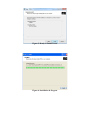
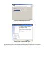
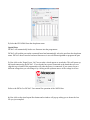
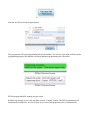
1
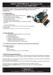
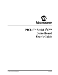
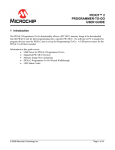
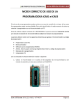
BASIC CHIPINO Manual
Installing the Software
The PICBASIC PRO compiler sample version comes with its own windows editor for writing the
programs and sending the binary file to the programmer. The editor is called the MicroCode Studio.
The PICkit 2 programmer software has a stand-alone application which allows us to use the PICkit 2 or
with the MicroCode Studio editor to one click compile and program the PIC microcontroller using the
ICSP. We have to set all this up on your PC before we can create the first project. The steps we will
take are:
1) Download the PBP3 Demo version from melabs.com at:
http://pbp3.com/download.html or load from the CD included.
2) Install the PBP3 compiler and when asked for a registration key enter the registration key
included on your sales receipt. This will enable the Student version of PBP3.
3) Install MicroCode Studio Software (this is part of the PICBASIC PRO installation).
4) Setup the PICkit 2 software included on the PICkit 2 CD
Installing MicroCode Studio and PBP 3
You need to run the PBP 3 installation file so run the PBP3_Setup file to install the PBP 3 compiler.
The compiler will step you through several screens shown in Figures 1 thru .
Figure 1: First PBP 3 Installation Screen
Figure 2: License Agreement Screen
Figure 3: Default Installation Location
Figure 4: Windows Start Menu Title
Figure 5: Ready to Install Screen
Figure 6: Installation in Progress
Figure 7: Final Setup Screen
When the PBP 3 installation is complete the last screen (Figure 7) will offer to “Install MicroCode
Studio IDE”. Make sure that option is checked before clicking on the “Finish” button. The MicroCode
Studio will install automatically after you press Finish. It will also install MPLAB if you don’t have
that on your PC.
The MicroCode Studio will begin with the screen in Figure 8.
Figure 8: First MicroCode Studio Screen
Figure 9: License Agreement Screen
Figure 10: Default Location Installation Screen
Figure 11: Installation in Progress Screen
Figure 12: Final MicroCode Studio Screen
After installation is complete, start Microcode studio and it should look similar to the picture in Figure
13.
Figure 13: MicroCode Studio IDE
Install the PICKit 2 Programmer
Install the PICkit 2 Standalone Software from the PICkit 2 CD by clicking on the PICkit2Setup
installation file.
Follow through all the installation screens until the PICkit 2 is completely installed and a PICkit
2 icon appears on your desktop.
We’re now ready to program the BASIC CHIPINO.
Flash an LED
Now we can write our first program that will simply flash an LED connected to the pin 13 of the
CHIPINO module. This is a simple project but proves out the whole process of writing software,
programming the microcontroller and watching the application run.
Figure 2-1 shows the completed project built into a breadboard. The CHIPINO powers the breadboard
and the red LED will flash at a rate of ½ second on and ½ second off.
Figure 2-1: Flash LED Project
Hardware
The hardware is built on a breadboard that has letters lined up with the column of connections and
numbers for the rows. The connections can be reproduced based on the table of connections below.
Figure 2-2 also shows the schematic for this project.
Connection Table
CHIPINO
CHIPINO
Jumper
1k ohm
Red LED
-
Pin Digital 13 to a-11
GND to a-10
e-10 to f-10
e-9 to f-10
Anode i-11, Cathode i-10
Figure 2-2: Flash LED Schematic Software
'****************************************************
'* Name
: flash.pbp
'* Author : Chuck Hellebuyck
'* Notice : Copyright (c) 2012 Electronic Products
'*
: All Rights Reserved
'* Date
: 4/3/2012
'* Version : 1.0
'* Notes
:
'*
: CHIPINO
- Pin Digital 13 to a-11
'*
: CHIPINO
- GND to a-10
'*
: Jumper
- e-10 to f-10
'*
: 1k ohm
- e-9 to f-10
'*
: Red LED
- Anode i-11, Cathode i-10
'****************************************************
include "chipino.bas"
main:
HIGH D13
PAUSE 500
LOW D13
PAUSE 500
GOTO main
'LED on
'Delay 1/2 second
'LED off
'Delay 1/2 second
'Loop back and do it again
The software is quite simple because it uses some of the commands that make PBP3 easier to use that
many other compilers. The first section is required to include the chipino.bas file. This file defines all
the digital pins (D0 thru D13) and analog pins (A0-A4). You can view this file to see the setup and can
modify it if you want. PBP3 places the contents of the chipino.bas file directly at that location just as if
you typed it in. Therefore you can modify it for anything you want to be included in every CHIPINO
project you create.
include "chipino.bas"
The chipino.bas file also sets the program speed to match the 16 MHZ oscillator on the CHIPINO
module. The configuration settings are also handled by the chipino.bas file so the MCLR pin is external
and the write protection is turned off. You don’t have to worry about any of this if you are new to
programming Microchip PICs. The main point is you can modify the chipino.bas file if you are an
experienced programmer. The contents of chipino.bas are shown in Appendix C.
The main program loop begins with the label “main” followed by a semi-colon. We will use this
marker in a future GOTO command.
main:
The digital I/O pins on the CHIPINO are D0 through D13. The digital pins can be inputs or outputs.
The PIC16F886 has a couple of internal registers that control these direction of these pins to set them to
input or output. TRISC controls D0 through D7 and TRISB controls D8 through D13. The data to be
sent out the pin or read from the pin is then stored in PORTC register for D0 through D7 and PORTB
register for D8 through D13. These can be controlled by writing to the TRIS and PORT registers
directly but PBP3 makes all this easy as both of these registers are automatically controlled with the
HIGH or LOW commands. Both HIGH and LOW set the pins to an output and then set the PORT pin
to a 0 for LOW and a 1 for HIGH.
In this example the software uses the HIGH command to place a high signal on pin D13. This will light
the LED. PBP 3 doesn’t care if you use capitals or small case letters. The MCStudio should recognize
the command an automatically capitalize the command.
HIGH D13
'LED on
The next command is the PAUSE command. This command just creates a ½ second delay as the value
500 represents 500 milliseconds or ½ second.
PAUSE 500
'Delay 1/2 second
The program then turns the LED off by setting the same pin low.
LOW D13
'LED off
The same pause command line delays another ½ second.
PAUSE 500
'Delay 1/2 second
The program then uses the GOTO command to jump back to the main label and repeat the operation
over again.
GOTO main
'Loop back and do it again
Now that we have an understanding of the program, lets actually program the CHIPINO to flash the LED. Build
the project shown in Figure 2-1 on a breadboard or you can use the demo shield below. It has the connections
already soldered in place so just plug the shield into the CHIPINO module.
Figure 2-3: CHIPINO Demo Shield
How to Program CHIPINO:
1) Enter the software listing into the MicroCode Studio editor window and save it as flash.pbp or
you can download it from www.elproducts.com > Download page.
2) Make sure Target Processor window in MCStudio shows “16F886” (Figure 2-4).
3) Connect the CHIPAXE programmer to the development board with the PIC12F683 in its socket.
The dotted side of the ribbon cable should match up to the arrow on the CHIPAXE board
(Figure 2-4).
4) Click on the little arrow next to the compile/program button (it’s next to the target processor
window from step 2) and make sure “CHIPAXE” is selected (Figure 2-5).
5) Click on the compile/program button to program the CHIPAXE module (Figure 2-5).
This should compile your program and bring up the pk2cmd.exe command line pop-up window. You
should see it program and then complete the process. The pop-up window should close after a three
second delay. The red LED should be blinking on the development board. If you don’t get this working,
go back through the steps and see if you missed something. Getting a simple LED to flash is a great
first project.
Figure 2-4: Microcontroller Window
Figure 2-5: Connect PICkit 2 to the CHIPINO board
Figure 2-6: Compile Icon
Once you have compiled your PBP3 program without errors, it’s time to program the microcontroller.
The directions below show how to use the PICkit 2 or PICkit 3 programmer.
1) Open the PICkit Programmer software. A window similar to
below should be displayed (PICkit 3 screen shown).
2) Select the PIC16F886 from the drop down menu.
Special Note:
PICkit 3 will automatically load a new firmware into the programmer.
PICkit 2 will read the part on the connected board and automatically select the part from the drop down
menu. PICkit 2 doesn’t need to load new firmware as it uses a different algorithm to program the part.
3) Now click on the Target Power “On” box to make a check appear as seen below. This will power up
the board connected to the PICkit 3. If you already have power connected to the board then you can
skip this step as both PICkit programmers will sense the power is connected. If you want to run at a
different voltage then you can change it by clicking on the up/down arrows of the voltage level box.
Refer to the PICkit 2 or PICkit 3 User manual for operation of the /MCLR box.
4) Now click on the Auto Import Hex button and a window will pop up asking you to locate the .hex
file you just compiled.
Find the .hex file and click on Open button.
The programmer will begin programming the microcontroller. You will see a green bar scroll across the
programming progress bar and then a message indicating programming was successful.
PICkit 2 Success Screen
PICkit 3 Success Screen
5) The program should be running on your board.
6) Make any changes to your code and then click on “Compile” button. The PICkit programmer will
automatically load the new .hex file (if there are no errors) and program the device automatically.
7) When you’re done and are ready to shut down, click on Auto Import button to stop the automatic
update.
8) Uncheck the Target Power “On” box to shut off power to the PICkit and close the PICkit 3
application by click on the red x in the corner.
Next Steps
Simple next steps are to change the pause value to a lower number to flash the LED faster. You could
also connect the LED to a different pin and then change the number in the high and low command lines
to make that new connection pin flash the LED.