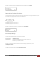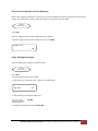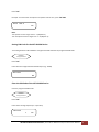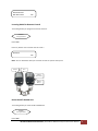
1
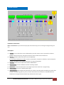
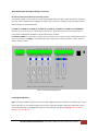
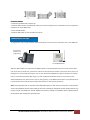
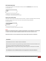
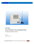
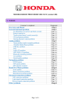
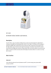
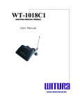
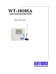
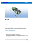
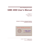
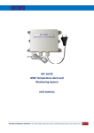
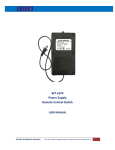
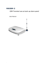
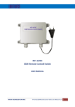
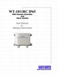
 WT‐1010SA Stand‐Alone GSM Alarm System User Manual and Installation Instructions Version: 1.2 Updated: 4 JAN 2012 WITURA CORPORATION SDN BHD | Stand‐Alone GSM Alarm System Instruction Manual 1
Introduction: The WT‐1010SA GSM Alarm System provides the ideal solution for residential, commercial applications, rural and farm security where traditional telephone lines are not available for security system communications. When no telephone service is available from your home, it ensures that critical alarm information reaches the central station. The WT‐1010SA uses a GSM communicator, no distance limits to receive alarm calls or remote control the alarm system, it can also call and sends text alerts to 8 pre‐set telephone number when intruder alarm triggers. Features: 1.
8 digital inputs: The system has the function to send SMS and call to the user in the event of input triggered. For example, Zone 4 connected to an electric door, when there is intruder or the electric door is open illegally, WT‐1010SA will receive short circuit impulse on Zone 4 and automatically sends a signal to the pre‐set number and notify the owner. 2.
It is possible to arm/disarm the unit remotely via remote control, SMS or phone call. Alternatively, it also can connect to the basic telephone to perform arm/disarm. 3.
Input alarm zoning can be edited and programmed up to 50 characters long. You can use this function to program any languages. You can change the displayed text by sending a command by SMS to the unit. For examples, changing the zone 4 to “DOOR OPEN”. 4.
If the alarm zoning is not enough, the system is offering “lopping concept” It can lop up to 50 zoning. 5.
2 remote control outputs: These heavy‐duty relay outputs can be turned on and off remotely through SMS. Remote control will be reachable by sending an SMS. For example SMS/Call in to switch on lighting, air conditioning system, generator, sensor or other equipment. 6.
Automatically call to 8 pre‐program phone numbers while alarming. The WT‐1010SA also will SMS to 8 programmable phone number to notify the user if any intruder. 7.
Open your auto gate with your basic telephone. Connect the WT‐1010SA with the auto gate and your house basic telephone. Besides you can use the WT‐1010SA as your house telephone, you also can open your auto gate by pressing a command at the basic telephone. WITURA CORPORATION SDN BHD | Stand‐Alone GSM Alarm System Instruction Manual 2
8.
Most of the countries, GSM Mobile operator offer cheaper call plan compared to telecom landline. It can connect to the basic telephone to make call and if any intruder, the WT‐1010SA will cut the telephone call and send the alarm messages first. 9.
In order to prevent professional thief to disconnect GSM by using “GSM Jammer”, the WT‐1010SA will activate the output relay 1 to trigger the siren if signal drop immediately. 10.
The owner will automatically received the SMS text messages for “Power Failure”, “Input 1 – Input 8 Triggered”, “GSM Alive” if any of the above having problem. 11.
Auto test reporting system – after the owner program the reporting time, the WT‐1010SA will dial the programmable number to inform that “GSM Alive”. This is to make sure that in case of emergency, the GSM still functioning well. 12.
Standby rechargeable battery to prevent power failure or electricity cut off by intruder. The GSM will function as normal when no electricity supply. LCD display to check the GSM signal strength and battery capacity. INTERNAL VIEW LCD Display
SIM Card Holder
RF Receiver GSM Module
Battery Backup Connector Main Switch Jumper
DC Power Connector Phone Port
Line Port 8 Digital Inputs
2 Relay Outputs
Antenna Connector WITURA CORPORATION SDN BHD | Stand‐Alone GSM Alarm System Instruction Manual 3
WIRING DIAGRAM Installation Instructions: Note: It is essential that you read the step by step instructions fully prior to installing and programming the unit. Description: 1.
Antenna: connect the antenna to the GSM module; place the antenna as far as possible from the WT‐
1010SA and do not leave any coiling of the antenna cable to avoid radiant interference 2.
SIM Card: disable the PIN code and set it to 1234 (default) For Transmitter Mode (Data or SMS): as with any transmitter, it requires an identifier, receiver telephone numbers, etc (refer to the complete information on Programming page) 3.
Line Port: connect the line input to the PSTN or ISDN network. 4.
Relay Outputs: connect to additional remote controlling outputs. 5.
Phone Port: connect the phone port to any single line phone to make calls or programming. 6.
Power Supply: connect to a 15VDC power supply 7.
Operating State: Approximately 20s after power up check the operating state indicated by the Power LED: the LED is steady during power up phase, and then blinks when the connection to the GSM network is established. The Signal indicator LED will stay lit whenever there is signal. WITURA CORPORATION SDN BHD | Stand‐Alone GSM Alarm System Instruction Manual 4
WT‐1010SA Inputs & Outputs Wiring Instructions: R1 (OUT1) and R2 (OUT2) Remote Controlling Outputs These Relay outputs can be turned on or off remotely by SMS. When sending an SMS command for switching the relay, the WT‐1010SA will turn ON/OFF the output relay and sends a message to notify the administrator that the output has switched ON/OFF. L1 (ZONE 1), L2 (ZONE 2), L3 (ZONE 3), L4 (ZONE 4), L5 (ZONE 5), L6 (ZONE 6), L7 (ZONE 7) and L8 (ZONE 8) Connect L1, L2, L3, L4, L5, L6, L7 and L8 inputs to the sensors, when there is a short‐circuit impulse on the inputs the WT‐1010SA will send SMS or Call the administrator numbers. For Example: ZONE 1 is connected to a motion sensor, when there is an intrusion the WT‐1010SA will receive a short circuit impulse on ZONE 1 and automatically sends a signal to the monitoring station and also sends an SMS to notify the owner. Inputs and Outputs Wiring Diagram Installing the SIM Card: Note: Installing the SIM Card. Please be sure the initial 4 digits PIN code of the SIM card is disabled. This can be done by placing it in an unlocked mobile phone and first checking if the SIM requested any PIN code. If this is the case the PIN code can be disabled using the security settings on the phone. Warning! The WT‐1010SA identifies only 3V SIM Card. WITURA CORPORATION SDN BHD | Stand‐Alone GSM Alarm System Instruction Manual 5
Proceed as follows: 1. Slide back the SIM holder and lift it up 2. Slide the SIM card into the SIM holder making sure that the clipped corner of the SIM card lines up with the clipped corner of the SIM holder 3. Close the SIM holder 4. Slide the SIM holder to lock the SIM card in place PROGRAMMING THE UNIT To program the unit you just need any fixed line telephone and connect it to the Phone port on the GSM unit. Any fixed line telephone for programming WT‐1010SA GSM Unit After the GSM module is connected to the GSM network, an attached fixed line phone can be used to make calls. If you pick up the phone, you will hear a dial tone. Simply dial the number you want to call (as if you are dialling from a normal fixed line phone). You can also dial the WT‐1010SA unit’s phone number from another phone, and its attached phone will ring as a normal landline phone would. If there is a busy tone on the attached telephone set, either the line you are calling is busy, or the GSM communicator is busy with previous communication at that moment (for example data transfer to the monitoring station). Note: Some telephone sets are sensitive to the GSM radio signal. For this reason you may hear a characteristic noise in the telephone receiver when calling. If the noise is disturbing, change the location of the phone set (try to keep it as far as possible from the WT‐1010SA unit antenna). Usually it is possible to find a suitable location for the phone with minimal level of interference. WITURA CORPORATION SDN BHD | Stand‐Alone GSM Alarm System Instruction Manual 6
ENTER PROGRAM MODE To enter program mode, pick up the telephone handset and dial **12345678# (default installer code) The display will show HAND FREE.... The GSM Unit is now in Programming Mode. To exit program mode simply hang up the handset. Program the Installer Code The installer code is used to access program mode via handset. To program a new 8 digit installer code simply press *0* in program mode. Enter the new installer code followed by # (eg. 87654321#) The display will show NEW PASSWORD: 87654321# To exit programming mode simply hang up the handset. NOTES: DO NOT LOSE THE INSTALLER CODE AS IT CANNOT BE RECOVERED IF LOST OR FORGOTTEN. YOU WILL NEED TO CONSULT WITH OUR TECHNICAL PERSONNEL FOR RESETTING THE SYSTEM TO DEFAULT STATE. Admin Phone Number 1 must be programmed to allow sending of SMS commands to the GSM Unit ATTENTION: PROGRAMMING METHODS – HANDSET AND SMS COMMANDS Please note that some options are programmed using a telephone handset connected to the GSM unit and other options are programmed by SMS message sent from a mobile phone. SMS COMMAND options are programmed by sending an SMS message from a mobile phone to the GSM Unit. The mobile phone used to send SMS Commands must be programmed as Admin Phone Number 1. WITURA CORPORATION SDN BHD | Stand‐Alone GSM Alarm System Instruction Manual 7
Program the Admin Phone Numbers Up to 8 Admin phone numbers can be programmed. These are mobile phone numbers to which the GSM Unit can send SMS messages, such as alarms from inputs or system messages. Here you should program the technical or security personnel numbers etc. You can program the unit to send SMS alarms to one or all Admin numbers. HANDSET In Program Mode Press *1* to program the Admin Phone Number 1. Enter the phone number followed by # (eg. 0124694739#) TEL: 0124694739 1# To program Admin Phone Number 2 to 8, repeat the sequence above using *2*, *3*, *4*, *5*, *6*, *7*, *8* To DELETE a Phone Number enter # with no phone number. eg. To delete Admin Number 1. HANDSET In Program Mode Press *1*# To program the Admin Phone Number by SMS send: SMS Command: *TEL[N]#[phone number] N = Admin position 1 – 8
[phone number] = Admin phone numbers Example, to program phone number 0163934857 as “Admin 1” send: *TEL1#0163934857 The GSM unit will send this reply message: TEL1=0163934857 WITURA CORPORATION SDN BHD | Stand‐Alone GSM Alarm System Instruction Manual 8
Enquire all Admin Phone Numbers To display all the Admin Phone Numbers locally using a handset. HANDSET In Program Mode Press *36* Each Admin Phone Number will be displayed in sequence: ADMIN: 1: 0124694739 Area Code / Phone Number Prefix To program prefix digits which will be automatically dialled before any phone number. HANDSET In Program Mode Press *24* Enter the prefix (max. 4 digits) followed by # (eg. 04#) AREA CODE: 04 OK Note: Once programmed, the Phone Number Prefix cannot be deleted it can only be replaced by a new prefix. Use *25* option to enable and disable dialling of the prefix. Enable / Disable Phone Number Prefix Use this option to enable the dialling of the Phone Number Prefix. HANDSET In Program Mode WITURA CORPORATION SDN BHD | Stand‐Alone GSM Alarm System Instruction Manual 9
Press *25* To enable the Phone Number prefix press 1# To disable the Phone Number prefix press 0# ENABLE AREA? Setting the Delay Time for Sending the Destination Number This setting enables the dialled destination number to be sent out automatically after a preset time. HANDSET In Program Mode Press *9* Enter the Delay time (Max. 2 digits) followed by # (e.g. 05#) Dttransmit: 05 OK Program the Alert Recipients This option sets which of the 8 Admin Phone Numbers will receive SMS alerts. HANDSET In Program Mode Press *22* to select the option Enter either the digit 0 (No alert) or 1 (Send alert) for each of the 8 Admin Phone Numbers, followed by #. Example 1, to enable all Admin Numbers for alerts, press 11111111# SECH: 11111111 OK Example 2, to enable only Admin Numbers 1, 2 & 3 for alerts, press 11100000# WITURA CORPORATION SDN BHD | Stand‐Alone GSM Alarm System Instruction Manual 10
SECH: 11100000 OK To program the alert recipients by SMS, send: SMS Command: *SECH#XXXXXXXX XXXXXXXX = stands for position of each of the 8 Admin Phone Numbers, Enter either the digit 0 (No Alert) or 1 (Send Alert) Example: to enable all Admin Numbers for alerts, send: *SECH#11111111 The GSM unit will send this reply message: SECH‐11111111 Enquire the Setting of Alert Recipients Check the setting of alert recipients using a handset. HANDSET In Program Mode Press *47* The Alert Recipients will be displayed in sequence: SECH: 11110000 Setting the Calling Group of Administrator This setting will enable the system to call the certain group of administrator numbers when Input triggered or AC power failure. HANDSET In Program Mode Press *23* Enter the number 1 – 8 (Max. 1 digit) followed by # WITURA CORPORATION SDN BHD | Stand‐Alone GSM Alarm System Instruction Manual 11
Example: to enable the system to call the first 3 administrator numbers, press 3# CALL: 3 OK Setting the Waiting Time for Engaged Call In the event the administrator has not answered the call or engaged, it could take a while for the WT‐1010SA to call the next number. This setting allows you to shorten the waiting time when it is busy or engaged. HANDSET In Program Mode Press *37* Enter the Waiting Time (Max. 2 digits in seconds) followed by # (e.g. 25#) Example: to program the waiting time as 25 seconds, press 25# Wait Time: 25 OK Note: The Waiting time range from 20 – 59 seconds (Default: 30 seconds) Program the PSTN Failure Options This function enables the possible alarm action for PSTN failure. HANDSET In Program Mode Press *45* to program the PSTN Failure alarm options PSTN Failure Options ME: Send SMS alert when PSTN failure AL: Activate the strobe light/siren when PSTN failure CA1: Call Admin number when PSTN failure CA2: Call Admin number when PSTN restored WITURA CORPORATION SDN BHD | Stand‐Alone GSM Alarm System Instruction Manual 12
Enter either the digit 0 (Disable) or 1 (Enable) for the 4 possible actions for the PSTN failure alarm, followed by #. Example: To enable the system to send SMS alert and activate the strobe light when PSTN failure, press 1100# PST: ME:1 AL:1 CA1: 0 CA2: 0 OK Note: If the system calls you when the PSTN failures simply answer the call and press # to acknowledge the alarm and the system will stop calling you. PSTN Failure Message This option sets the SMS text which is sent when the PSTN line failure. SMS Command: *PSOF#[message] [message] = Up to 50 alphanumeric characters. Letters and numbers only, no special characters. Example: To program the system to send the SMS message “PSTN Failure”, send: *PSOF#PSTN Failure The GSM unit will send this reply message: PSOF‐PSTN Failure PSTN Restoral Message This option sets the SMS text which is sent when the PSTN line is restored. SMS Command: *PSON#[message] [message] = Up to 50 alphanumeric characters. Letters and numbers only, no special characters. Example: To program the system to send the SMS message “PSTN Restored”, send: *PSON#PSTN Restored The GSM unit will send this reply message: PSON‐PSTN Restored WITURA CORPORATION SDN BHD | Stand‐Alone GSM Alarm System Instruction Manual 13
Program the Power Failure Options This function enables the possible alarm action for power failure. HANDSET In Program Mode Press *34* to program Power Failure alarm options AC Power Failure Options ME: Send SMS alert when power failure AL: Activate the strobe light when power failure CA1: Call Admin number when power failure CA2: Call Admin number when power restored Enter either the digit 0 (Disable) or 1 (Enable) for the 4 possible actions for the power failure alarm, followed by #. Example: To enable the system to send SMS alert and activate the strobe light when power failure, press 1100# ADC: ME:1 AL:1 CA1: 0 CA2: 0 OK Note: If the system calls you when the power failures simply answer the call and press # to acknowledge the alarm and the system will stop calling you. Enable/Disable the Alarm Inputs Function This option allows you to enable/disable the function of alarm inputs. HANDSET In Program Mode Press *16* to enable/disable the function of 8 alarm inputs To enable the function of all alarm inputs press 11111111# To disable the function of all alarm inputs press 00000000# WITURA CORPORATION SDN BHD | Stand‐Alone GSM Alarm System Instruction Manual 14
CTR SET: 11111111 Note: 11111111 stands for enable position of each of the alarm inputs. Enter either the digit 0 (Disable) or 1 (Enable) Program the Alarm Input Options This option enables the possible actions of 8 alarm inputs of the unit. HANDSET In Program Mode Press *26* to program Input 1 alarm options Press *27* to program Input 2 alarm options Press *28* to program Input 3 alarm options Press *29* to program Input 4 alarm options Press *30* to program Input 5 alarm options Press *31* to program Input 6 alarm options Press *32* to program Input 7 alarm options Press *33* to program Input 8 alarm options Input Options OP: Send SMS Alert when Input Triggered (Alarm Input to +12V) CL: Send SMS Alert when Input Restored (Remove +12V from Input) AL: Activate Strobe Light / Siren when Input Triggered CA1: Call Admin number when Input Triggered CA2: Call Admin number when Input Restored Enter either the digit 0 (Disable) or 1 (Enable) for the five possible actions for the input, followed by #. Example: To enable Input 1 to send SMS Alarm and Restoral messages and activate the strobe light when input is triggered, press *26*11100# IN1: OP:1 CL:1 AL:1 CA1: CA2: OK Follow the same procedure for input 2, 3, 4, 5, 6, 7 & 8. WITURA CORPORATION SDN BHD | Stand‐Alone GSM Alarm System Instruction Manual 15
Note: If the system calls you when the input triggered simply answer the call and press # to acknowledge the alarm and the system will stop calling you. Input Alarm Message This option sets the SMS text which is sent when an input is triggered. SMS Command: *USE[N]#[message] [N] = Input number 1 ‐ 8. [message] = Up to 50 alphanumeric characters. Letters and numbers only, no special characters. Example: To program Input 1 to send the SMS message “ZONE 1 Open”, send: *USE1#ZONE 1 Open The GSM unit will send this reply message: USE1‐ZONE 1 Open Input Restoral Message This option sets the SMS text which is sent when an input is restored. SMS Command: *USC[N]#[message] [N] = Input number 1 ‐ 8. [message] = Up to 50 alphanumeric characters. Letters and numbers only, no special characters. Example: To program Input 1 to send the SMS message “ZONE 1 Closed”, send: *USC1#ZONE 1 Closed The GSM unit will send this reply message: USC1‐ZONE 1 Closed Program the Strobe Light / Siren Output Duration To program the strobe light / siren output duration on PIN24 and PIN25. The alarm time can be set between 00001 to 99999 seconds. Note that programming duration of 00000 seconds has no effect. HANDSET In Program Mode WITURA CORPORATION SDN BHD | Stand‐Alone GSM Alarm System Instruction Manual 16
Press *39* Example: To program the strobe light / siren output duration to 10 minutes, press *39*00600# Alarm Time: 00600 OK To program the strobe light / siren output duration by SMS, send: SMS Command: *ALTM#[time] [time] = strobe light / siren output duration in seconds between 00000 and 99999 seconds. Example: To program the output duration to 10 minutes send: *ALTM#00600 The GSM unit will send this reply message: ALTM‐00600 Enable / Disable the Activation of Strobe Light / Siren Output when Input Triggered Use this option to enable or disable the activation of strobe light / siren output when the input triggered. SMS Command: *ALM[N]#X [N] = Input number 1 ‐ 8. X = 1 (Enable) or 0 (Disable) Example: To enable this function for input 1, send: *ALM1#1 The GSM unit will send this reply message: ALM1‐ON Arm / Disarm all the Alarm Inputs This option allows you to Arm / Disarm all the alarm inputs with handset. HANDSET In Program Mode Press *40* To arm all the alarm inputs press 1# To disarm all the alarm inputs press 0# WITURA CORPORATION SDN BHD | Stand‐Alone GSM Alarm System Instruction Manual 17
Input ARM? 1 OK To Arm / Disarm all the alarm inputs by SMS, send: SMS Command: *DARM#X X = 1 (ARM) or 0 (DISARM) Example: To arm all the alarm inputs, send: *DARM#1 The GSM unit will send this reply message: DARM‐ON Note: When it is armed, the system will reply a message: Host has been ARMED When it is disarmed, the system will reply a message: Host has been Disarm Set the Arm Delay Time This setting allows you to program the Arm Delay Time for alarm inputs. HANDSET In Program Mode Press *41* Enter the Arm Delay Time (Max. 2 digits in seconds) followed by # (e.g. 10#) Example: to program the Arm Delay Time as 10 seconds, press 10# ARM Delay Time 10 OK Note: The Arm Delay Time range from 20 – 59 seconds (Default: 00 seconds) WITURA CORPORATION SDN BHD | Stand‐Alone GSM Alarm System Instruction Manual 18
Set the Time Clock This setting allows you to program the internal clock of the device. The time is set in 24HR format. HANDSET In Program Mode Press *35* to program the internal clock Example: To program the internal clock as 12:00:00, press *35*120000# TIME: 12:00:00 OK To program the internal time clock by SMS, send: SMS Command: *SETM#HH:MM:SS HH = Hour MM = Minutes SS = Seconds Example: To program the time to be 5:30PM, send: *SETM#17:30:00 The GSM unit will send this reply message: Set Time OK Set the Auto Test Report Options This setting allows you to choose the options of Auto Test Report. HANDSET In Program Mode Press *44* Auto Test Report Options Time Call?: Call the administrator phone number on the programmed time section Time Message?: Send SMS to the administrator on the programmed time section Enter either the digit 0 (Disable) or 1 (Enable) for the two possible actions for the report, followed by #. WITURA CORPORATION SDN BHD | Stand‐Alone GSM Alarm System Instruction Manual 19
Example: To enable the system to send SMS only for Auto Test Report, press *44*01# Time Call?: 0 Time Message?: 1 OK Program the Auto Test Report Time Sections This setting allows the system to send the test report to the administrator on the programmable time. Up to 2 time sections can be programmed. The time is set in 24HR format. HANDSET In Program Mode Press *42* to program the time section 1 Press *43* to program the time section 2 Example: To program the time section 1 as 12:00:00, press *42*120000# Alarm Time1 12:00:00 OK Auto Test Report Message This option sets the SMS text which is sent for Auto Test Report. SMS Command: *DSME#[message]. [message] = Up to 50 alphanumeric characters. Letters and numbers only, no special characters. Example: To program the system to send the Auto Test text message “System Online”, send: *DSME#System Online The GSM unit will send this reply message: DSME‐System Online WITURA CORPORATION SDN BHD | Stand‐Alone GSM Alarm System Instruction Manual 20
Set the Account Number for Event Reporting When Input triggered, PSTN failure or power failure, the WT‐1010SA will dial the programmable central station number and transmit the account number along with Contact‐ID to the central station. HANDSET In Program Mode Press *38* Enter the 4 digits account number followed by # (e.g. 1234#) Example: to program the account number as 1111, press 1111# ATACC: 1111 OK Check GSM Signal Strength Check the GSM signal strength by handset or SMS. HANDSET In Program Mode Press *46* The display will show the signal strength. 0 = Poor signal, 31 = Best signal, 99 = unknown or not detectable CSQ <28> OK To check GSM signal strength by SMS, send: SMS Command: *CSQ?# The GSM unit will reply for example: CSQ=<28> WITURA CORPORATION SDN BHD | Stand‐Alone GSM Alarm System Instruction Manual 21
Check Version To check the software and hardware version by handset. HANDSET In Program Mode Press *20* The display will show, for example: HW: 1.1ver SW: 1.0 Ver MW: 1.0ver Remote Control Outputs by SMS This allows you to turn outputs on by SMS. This can be used to switch on lights or open the gate with a relay. Note: The mobile phone used to send SMS commands must be programmed as Admin Phone Number. SMS Command: *RLY[N]#[time] N = Output number 1 or 2 [time] = relay on time in seconds between 00000 and 99999 seconds. To toggle outputs, send the text ON or OFF instead of a time value. See the example below. Example 1: To program Output 1 to stay on for 20 seconds, send: *RLY1#00020 The GSM unit will reply: RLY1‐00020 Example 2: To program Output 1 to stay on indefinitely, send: *RLY1#ON The GSM unit will reply: RLY1‐ON WITURA CORPORATION SDN BHD | Stand‐Alone GSM Alarm System Instruction Manual 22
Control Outputs by handset This allows you to turn outputs on by handset. HANDSET In Program Mode Press *10* to switch on Output 1 Press *11* to switch on Output 2 Example: To activate Output 1 for 10 seconds and send an SMS message when the output has turned off, press *10*000101# RLY1: 00010 RE: 1 The options for RE: are 0 = Do not send SMS reply when the output turns off. 1 = Send SMS reply when the output turns off. Setting the SMS Reply for Output Relay Off This setting allows you to enable/disable the SMS reply when the output turns off by SMS. SMS Command: *RER[N]#X N = Output number 1 or 2 X = 1 (Enable) or 0 (Disable) Example: To enable the SMS reply function for output relay 1, send: *RER1#1 The GSM unit will send this reply message: RER1‐ON Adjusting the Microphone and Speaker Volume This setting allows you to adjust the Microphone and Speaker volume of the WT‐1010SA unit by handset. HANDSET In Program Mode WITURA CORPORATION SDN BHD | Stand‐Alone GSM Alarm System Instruction Manual 23
Press *15* Example: To set both the microphone and speaker volume to 4, press *15*44# SPK: 4 MIC: 4 OK Note: The speaker volume ranges from 1 – 9 (Default: 5) The microphone volume ranges from 1 – 9 (Default: 5) Setting PIN Code for the WT‐1010SA Device This setting allows the WT‐1010SA to recognize the SIM card with the programmed PIN code. HANDSET In Program Mode Press *12* Enter twice the 4 digits PIN code followed by # (e.g. 1234#) PIN: 1234 OK Clear the PIN Code of the WT‐1010SA Device Clear the programmed PIN code. HANDSET In Program Mode Press *14* Enter either the digit 0 (Cancel) or 1 (Confirm) Clear PIN? 1 OK WITURA CORPORATION SDN BHD | Stand‐Alone GSM Alarm System Instruction Manual 24
Check the PIN Code of the WT‐1010SA Device Check the programmed PIN code. HANDSET In Program Mode Press *13* The PIN code will be displayed as below PIN code is: 1234 Enable SIM PIN Protection This setting allows you enable SIM PIN protection. HANDSET In Program Mode Press *18* Enter the 4 digits PIN code followed by # (e.g. 1234#) PIN Protected ON PIN: 1234 OK Disable SIM PIN Protection This setting allows you disable SIM PIN protection. HANDSET In Program Mode Press *19* Enter the 4 digits PIN code followed by # (e.g. 1234#) WITURA CORPORATION SDN BHD | Stand‐Alone GSM Alarm System Instruction Manual 25
PIN Protected OFF PIN: 1234 OK Learning Mode for Remote Control This setting allows you program the remote controls. HANDSET In Program Mode Press *17* Press any button on the remote control to learn RF Learn OK Note: You are allowed to add up to 5 remote controls to operate the system. Disarm Arm Activate Alarm Siren
Activate Relay 1
Reset the WT‐1010SA Unit This setting allows you reset the WT‐1010SA Unit. HANDSET In Program Mode Press *21* WITURA CORPORATION SDN BHD | Stand‐Alone GSM Alarm System Instruction Manual 26
Enter either the digit 0 (Cancel) or 1 (Confirm) Reset The Machine? 1 OK WITURA CORPORATION SDN BHD | Stand‐Alone GSM Alarm System Instruction Manual 27