1
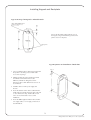
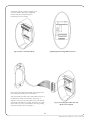
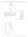
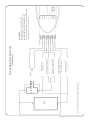
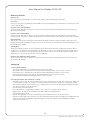
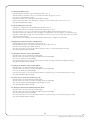
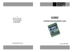
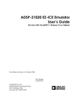
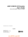
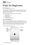
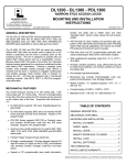
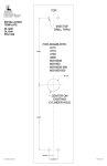
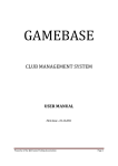
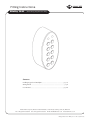
®
Fitting Instructions
RiteKey 30-01
ADAMS RITE
EUROPE LIMITED
(IP65 Rating Keypad Face Only)
Contents
Installing Keypad and Backplate ...............................................................page 1-3
Wiring Details..................................................................................................page 4
User Manual.................................................................................................page 5-6
Adams Rite Europe Ltd, Moreton Industrial Estate, London Road, Swanley, Kent, UK, BR8 8TZ
Tel: +44 (0)1322 668024 Fax: +44 (0)1322 660996 E-mail: [email protected] www.adamsrite.co.uk
Fitting Instructions for Ritekey 30-01. Rev 3 June 2005.
Installing Keypad and Backplate
Fig.1 Positioning of Fixing Holes and Cable Outlet
Cable Outlet, Drill Diameter
10mm for Cable Access
Remove the back plate, which is fitted to rear of
the keypad, using a 2mm Allen key provided and
put the screw in a safe place.
Fixing Holes
Fig.2 Preparation and Installation of Back Plate
Vert. CL
1. Select a suitable location to fit the keypad and mark
the position to two fixing screws and the cable
access hole as per fig.1
2. If fitting to brickwork use the rawl plugs provided
and drill two 6mm diameter holes to suit.
Otherwise, drill the two fixing holes 3mm in
diameter to allow a 4mm button head screw to cut
its own thread.
3. Install the cable run to the power supply and
the lock.
4. Ensure the diameter of the cable is sufficient for the
length of the run and the amperage draw of the lock
so as to minimise line drop. Alarm cable or bell
wire is not recommended for access control
installations.
5. Ensure the MOV supplied is fitted to the lock either
to its supply cables or on its supply connections on
its terminal block.
1
Fitting Instructions for Ritekey 30-01. Rev 3 June 2005.
Terminal block shown in position as shipped, note
its position with the cable entry pointing away
from the PCB. (The wall of the keypad is
particularly removed for clarity).
DOOR C
EXIT B
RETURN
COM
N/O
N/C
POWER
AC/DC
11-16V
Fig.3 Position of Terminal Block
Fig.4 Diagram Showing PCB Connections
Remove the terminal block from the PCB, which separates from
the terminal pins by pulling on the terminal block.
As the terminal block is lifted away it will reveal the functions of
the different pins written onto the PCB as shown in fig. 4
Make the connections to the terminal block as per the diagram
and refit the terminal block to the PCB. Please take care to refit
the block the correct way around with the cable entry pointing
away from the PCB as shown in diagram 3.
Fig 5. Connecting the Cable Run and
Block to the Keypad
2
Fitting Instructions for Ritekey 30-01. Rev 3 June 2005.
6. Once the back plate has been securely fastened to the application and the
terminal block has been correctly installed on the keypad PCB, the keypad
is ready to install onto the back plate.
Hook the keypad onto the back plate by the slot in the rear of the keypad
located at the top of the aperture as per fig.4. Pivot the keypad so that it
sits flat against the back plate and is in line with the tapped hole located in
the underside of the flange of the back plate. Tighten the Allen screw and
complete the remaining tasks as described.
Fig.3 Inserting Keypad Cable into Back Plate
Fig.4 Fitting Keypad to Back Plate
3
Fitting Instructions for Ritekey 30-01. Rev 3 June 2005.
Either/Or
MOV
Note: 1) The lock must also be fitted with the MOV supplied.
PSU
LOCK
12V DC PSU Positive, Link to
Door Relay Common
12V DC PSU Negative, Connect to
Negative Supply from Lock for both
Fail Safe and Fail Secure
Lock Relay N/C, Connect Positive
Supply form Lock Only if Fail Safe
Lock Relay N/O, Connect Positive
Supply from Lock Only if Fail Secure
Lock Relay Common,
Link to PSU Positive
Exit Button
Pair
(12VDC Shown)
Wiring Diagram For Ritekey 30-01
Not Used
N/C
N/O
COM
RETURN
EXIT B
DOOR C
Operating Voltage: 12 to 18 Volts AC or DC
Current Consumption: standby mode approx. 15ma
Maximum Draw: 130ma (not including door lock)
Door Relay: maximum rating 2 amps at the operating voltage
Service Temperature: +70 to –20 degrees C.
Specification
POWER
AC/DC
11-16V
Fitting Instructions for Ritekey 30-01. Rev 3 June 2005.
User Manual for RiteKey 30-01/02
Glossary of Terms
Master Code
The code used for programming the user codes and any changes to the default settings of the keypad.
User Code
The access code given to an individual user that will allow entry to the building but does not allow the user to change any of the
codes or default settings.
Duration of Door Unlocked Mode
The period of time that can be set between 01 and 99 seconds for which the electrical locking hardware can be unlocked to
allow entry to the building.
Duration of Door Latched Mode
The period of time that can be set between 01 and 99 minutes for which the electrical locking hardware can be held in the
unlocked position. This feature is activated by entering the user code followed by 0 and is useful on occasions such as deliveries.
Operating Mode
Once the user code has been entered the unit will switch for the duration of the Door Unlocked Setting to allow entry to the
building and the green LED will flash at a rate of one per second. An incorrect code will result in the red LED flashing once and
the unit will return to standby.
Standby Mode
The Mode in which the keypad is not in use and the function to which it returns after it has completed an operation. Or if an
operation is not concluded a period of time that can be adjusted from 01 to 99 seconds will lapse before the keypad reverts to
standby mode. This will also occur in programming. The period of time taken to revert back to the standby mode, this can be
adjusted from 1 to 99 seconds. This will also occur in programming.
Duration of the Exit Button Override Mode
The period of time that can be set between 01 and 99 seconds for which the electrical locking hardware can be unlocked to
allow exit from the building.
Setting Up
1. Factory Default Settings
• The Master Default Code is a 5 digit number and is factory set at 12345.
• The Duration of Door Unlocked Mode to unlock the electrical locking hardware is factory set at 10 seconds.
• The Duration of Door Latched Mode to unlock the electrical locking hardware is factory set at 10 minutes.
• The Exit Button Time Delay to unlock the electrical locking hardware is factory set at 10 seconds.
• The Duration the Exit Button Override Mode is factory set at 10 seconds.
2. Resetting the Master Code to Either 4 or 5 Digits
• This function only needs to be carried out if the master code is to be changed to a 4 digit code or having set a 4 digit code
a change back to a 5 digit code is required. Note that using this function will erase the memory of the keypad and will
therefore delete all of the User Codes from 01-50. If this function is to be carried out after initial programming, the existing
User Codes should be recorded before hand.
• Disconnect the power to the keypad.
• Press either button 4 or 5 (depending on whether a 4 or 5 digit code is required and keep it pressed.
• Apply power to the keypad and wait until the green LED is lit before releasing the button.
• The red LED should now be lit.
• Enter the first digit of the new master code and keep it pressed until the red LED is not lit and then release.
• Enter the remaining digits of the new master code, the red LED should not be lit when each digit is pressed until the full code
had been entered where it will light for approximately three seconds followed by the green LED flashing in standby.
• Write down the master code.
5
Fitting Instructions for Ritekey 30-01. Rev 3 June 2005.
3. To Change the Master Code
• Enter the default or old master code and wait for the LED to come on.
• Enter the default or old master code for a second time and wait for the green to come on.
• Press keys 00 and wait for the red LED
• Enter the new master code and the green LED will flash in standby.
• Write down the new master code and keep it in a safe place. Do not use the master code as a user code.
• The green LED will flash in standby.
4. To Create/Change the User Code
• Enter the 4 or 5 digit master code and wait for the red LED to come on.
• Enter the master code for a second time and wait for the green LED to come on.
• Press any two keys i.e. 01 to 50 to store the User Code Position Number and wait for the red LED to come on.
• Enter the new User Code, which must consist of 4 digits for a 4 digit master code and 5 digits for a 5 digit master code.
Regardless of the number of digits, do not use the master code as a user code. Do not use the same User Code for other
User Code Position Numbers.
• Write down the new 2 digit User Code Position Number and the new 4 or 5 digit User Code number.
5. Changing the Delay for the Back to Standby Mode
• Enter the Master Code and wait for the red LED to come on.
• Enter the Master Code for a second time and wait for the green LED to come on.
• Enter the code 66 and the green LED should be lit.
• Press any two keys from 01 to 99 for the new time delay (01 being 1 second and 99 being 99 seconds).
• The green LED will then flash in standby.
6. To Change the Duration of Door Latched Mode
• Enter the master code and wait for the red LED to light.
• Enter the master code for the second time and wait for the green LED to light.
• Press keys 71, and the green LED will light.
• Press any two keys from 01 to 99 for the new time delay in minutes (01 being 1 minute and 99 being 99 minutes).
• The green LED will then flash in standby.
7. To Change the Duration of Door Unlocked Mode
• Enter the master code and wait for the red LED to light.
• Enter the master code for the second time and wait for the green LED to light.
• Press keys 77, and the green LED will light.
• Press any two keys from 01 to 99 for the new time delay in seconds (01 being 1 second and 99 being 99 seconds).
• The green LED will then flash in standby.
8. To Delete all User Codes from Positions 01 to 50
• Enter the master code and wait for the red LED to light.
• Enter the master code for the second time and wait for the green LED to light.
• Press keys 88, and the red LED will light for approximately 3 seconds.
• The green LED will then flash in standby.
9. To Change the Duration the Exit Button Override Mode
• Enter the master code and wait for the red LED to light.
• Enter the master code for the second time and wait for the green LED to light.
• Press keys 99, and the green LED will light.
• Press any two keys from 01 to 99 for the new time delay in seconds (01 being 1 second and 99 being 99 seconds).
• The green LED will then flash in standby.
6
Fitting Instructions for Ritekey 30-01. Rev 3 June 2005.