1
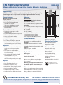
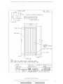
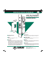
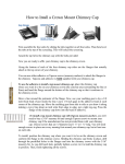
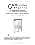
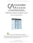
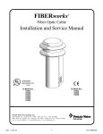
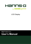
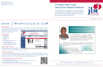
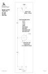
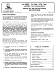
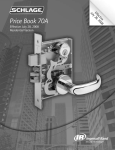
Controlled Access Inc. – HS336 Series Full Height ADA Gate Service and Installation Manual HS336 Series Full Height ADA Gate Service & Installation Manual Note: Successful installation depends on reading this manual. Important Note: Please keep this service manual after installation. If an installation is done by a construction company or outside installer, please pass this book along to the end user. Security Begins With Controlled Access 1636 W. 130th Street, Brunswick, OH 44212 Toll Free Phone: (800) 942-0829 | Fax: (800) 942-0828 / Phone: (330) 273-6185 | Fax: (330) 273-4468 Web: http://www.controlledaccess.com | E-mail: [email protected] 1 The High-Security Series HS336-ADA Manual or Electronic Passage Gate • Interior & Exterior Application The Truly “Custom” ADA Gate Our HS336-ADA is our ADA solution to perimeter security. This self-closing, heavy duty swing gate provides a wheelchair accessible 36” passage width (with an overall width of 43”). Its low voltage strike lock can be used mechanically or electronically depending on your needs. It is available in all of our standard finishes including stainless steel (304 or 316), carbon steel with powder coating, or hot-dipped galvanized, to match our turnstiles perfectly. Your choice of standard vertical bars or reach prevention mesh allows for a custom experience. A treadplate walkway adds additional rigidity and helps in preventing installation mishaps. HS336 - Front (powder coat with mesh) Hydraulic door closer included with gate. Power Door Opener is available for additional charge. Full exit push-bar, guard and mesh should be used for Free Exit situations. Push-bar not available without mesh. HS336 (stainless steel) *All models available in stainless steel, powder coat or galvanized. HS336 - Back (stainless steel with mesh) We’re the #1 Choice of Top Architects, Security Pros and Engineers For two decades, Controlled Access has been the globally trusted name in pedestrian control equipment. Made in Ohio and shipped worldwide, we are the first choice of leading architects, facility managers, security consultants and engineers. Whether your project requires high security full-height turnstiles, waist-high units, or matching ADA accessible gates, Controlled Access is the secure choice. And, we’re experienced in access control systems, from card readers to biometric scanning, to give you the power to control access. CONTROLLED ACCESS, INC. Built in the USA The Leader in Pedestrian Access Control 1636 West 130th Street | Brunswick, Ohio 44212 | Ph: 330.273.6185 | Fax: 330.273.4468 | Toll-Free Ph: 800.942.0829 | Toll-Free Fax: 800.942.0828 E-mail: [email protected] | www.controlledaccess.com 0315 The High-Security Series HS336-ADA Manual or Electronic Passage Gate • Interior & Exterior Application Applications: Ideal for controlling orderly flow of foot traffic in both indoor and outdoor settings (matching gate to our High-Security Full-Height Single and Tandem Turnstiles) Product Features: Materials and Finishes available in your choice of: • Hot dipped galvanized carbon steel • Carbon steel with powder coating (standard color is black/ other colors available upon request) • Our signature 304 Stainless steel/ No. 4 satin finish Design & Construction: • Designed for secure operation with asthetics in mind • Featuring fully welded exterior components • Minimal exposed hardware • Heavy gauge materials meeting ASTM standards Installation Methods: • Core drilling of frame posts (preferred) • 1/2” concrete anchors from tread plate (requires removing core legs from frame) Operation: • Field reversable electronic strike (24VDC) can be set to lock or open on power failure • Gate can also be unlocked with no power by configuring the strike to fail lock and using a key • Gate automatically swings closed with standard hydraulic door closer • Voltage for electronic strike can be taken from nearby turnstile power supply Options: • • • • Reach prevention mesh Panic bar with mesh for free exit Magnetic lock (replaces strike) Motorized gate opener (requires 110VAC, adds 3” to overall height of gate) • Push buttons (Wired or wireless) • Variable passage widths (up to 40”) • Additional options available upon request Measures: HS336-ADA Size of opening (pedestrian clearance) HS336-ADA 36” (914mm) Frame 2” x 3” (51mm x 76.2mm) 11 gauge box tubing Swing Gate 2” x 2” (51mm x 51mm) 11 gauge box tubing Exterior Height 91” (2331mm) Interior Height 87.872” (2230mm) Available Door Filler Materials 1 1/2” Diameter 14 gauge (38mm) 1 3/4” Diameter 14 gauge (44mm) 3/4” #9 Expanded Metal Mesh (Flattened) Standard Hardware: Door Closer: Norton 9300 Series with Aluminum Finish Deadlock: Adams Rite 4510 Series with 31/32” Backset Strike: Adams Rite 7100 Series Electronic Strike, 24VDC Cylinder: Schlage C keyway - standard SFIC available Optional Hardware: Door Opener: Norton 5730 Low Energy Operator, Aluminum Push to Exit Panic Bar: Adams Rite 8400 Exit Device, Aluminum We can source additional custom hardware choices. Please provide your required specs for a quotation. Dimensions are approximate. Electrical Specifications: UL Listed Electronic Strike: Input Voltage: 24VDC Input Current: 170 mA Standards and Codes: Austenitic stainless steel: ASTM A240, A249, A276 Hot rolled steel: AISI C-1020, AISI C-1018 Hot dipped galvanizing: ASTM A-143, ASTM A-153-80 Stainless steel fasteners: ASTM A-320 American Welding Society (AWS) Standard D 1.1 Matching Full-Height Turnstiles Available in Single (HS427-S, HS430-S, HS439-S, HS448-S) and Tandem (HS427-T, HS430-T) Designs. Controlled Access, Inc. is a registered ISO 9001:2008 company Warranty: Units are warranted against defects in materials and workmanship for a period of one year from date of delivery. See warranty information for specific details. CONTROLLED ACCESS, INC. The Leader in Pedestrian Access Control 1636 West 130th Street | Brunswick, Ohio 44212 | Ph: 330.273.6185 | Fax: 330.273.4468 | Toll-Free Ph: 800.942.0829 | Toll-Free Fax: 800.942.0828 E-mail: [email protected] | www.controlledaccess.com 0315 Controlled Access Inc. – HS336 Series Full Height ADA Gate Service and Installation Manual Security Begins With Controlled Access 1636 W. 130th Street, Brunswick, OH 44212 Toll Free Phone: (800) 942-0829 | Fax: (800) 942-0828 / Phone: (330) 273-6185 | Fax: (330) 273-4468 Web: http://www.controlledaccess.com | E-mail: [email protected] 2 Controlled Access Inc. – HS336 Series Full Height ADA Gate Service and Installation Manual Pre-installation Tips for the HS336 Full Height ADA Gate Before installing the HS336 ADA Gate, make sure to review these pre-installation tips to ensure a successful installation. Before you get started: We recommend core drilling to install the HS336 gate. Should you decide not to core drill, cutting the legs off underneath the tread plate is required. If you are electronically locking or unlocking the gate, be aware of the various methods to accessing the electronic strike before installing. Details are provided later in this manual. Although the strike is field reversible, each gate comes pre-configured to lock or open upon power failure. We configure these gates based on how they were ordered. Manual gates will always need to have the strike configured as fail lock. It is crucial that the frame is installed squarely. The provided floor plate on the gate helps to ensure a square installation, but anchoring to unlevel concrete may throw this off. Note: Failure to install the frame square can result in the gate failing to lock properly. Take advantage of the provided spacers and floor plate when core drilling to ensure proper installation. Security Begins With Controlled Access 1636 W. 130th Street, Brunswick, OH 44212 Toll Free Phone: (800) 942-0829 | Fax: (800) 942-0828 / Phone: (330) 273-6185 | Fax: (330) 273-4468 Web: http://www.controlledaccess.com | E-mail: [email protected] 3 Controlled Access Inc. – HS336 Series Full Height ADA Gate Service and Installation Manual Electrical Information for the HS336 Full Height ADA Gate Should your facility require it, the HS336 can easily be integrated into access control systems. Each gate has a bracket on each side of the top which has conduit access. This bracket can also be utilized to bolt onto a Controlled Access full height turnstile as well (the conduit holes align on the mainframe of the turnstile as well as the bracket on the gate). Additionally, the 2” x 3” frame can be utilized from the floor to provide conduit access to the electronic strike. The diagram below calls out these convenient locations. If utilizing the strike electronically, provide 24VDC voltage to unlock it. Depending on whether the strike fails locked or fails open, a normally open or normally closed relay contact is required. Strikes configured to fail lock require voltage to unlock, while fail open strikes require voltage to lock. The key or optional panic bar can always be used to override this and manually unlock the gate. Security Begins With Controlled Access 1636 W. 130th Street, Brunswick, OH 44212 Toll Free Phone: (800) 942-0829 | Fax: (800) 942-0828 / Phone: (330) 273-6185 | Fax: (330) 273-4468 Web: http://www.controlledaccess.com | E-mail: [email protected] 4 Controlled Access Inc. – HS336 Series Full Height ADA Gate Service and Installation Manual Installation Instructions for the HS336 Full Height ADA Gate Preferred Installation Method 1. 2. 3. 4. 5. 6. Review pre-installation tips, verify gate swing direction & layout holes to be drilled. Core drill 4” diameter holes 40” on center, 6” deep. Fill core drilled holes with fast set mortar, following the manufacturer’s instructions. Lift the gate vertically and slide the legs into core drilled holes. Install ¼” flat head Tapcons™ into inner holes on the tread plate to secure the walk path. Attach gate to turnstile or adjoining wall / structure utilizing mounting brackets on both sides of the gate. 7. Make electrical connections to the strike, if required. Alternate Installation Method 1. 2. 3. 4. 5. 6. 7. 8. 9. 10. Review pre-installation tips, verify gate swing direction & layout holes to be drilled. Remove 2” x 3” x 6” legs from underside of floor plate with a band saw. Utilizing the floor plate as a template, mark the outer holes for ½” concrete anchors Drill ½” holes into the concrete pad for wedge type concrete anchors. Install wedge type concrete anchors into ½” holes, following the manufacturer’s directions for concrete anchor installation. Place gate onto anchors. Install nuts onto ½” anchors to ensure the gate is properly secured to the ground. Install ¼” flat head Tapcons™ into inner holes on the tread plate to secure the walk path. Attach gate to turnstile or adjoining wall / structure utilizing mounting brackets on both sides of the gate. Make electrical connections to the strike, if required. Security Begins With Controlled Access 1636 W. 130th Street, Brunswick, OH 44212 Toll Free Phone: (800) 942-0829 | Fax: (800) 942-0828 / Phone: (330) 273-6185 | Fax: (330) 273-4468 Web: http://www.controlledaccess.com | E-mail: [email protected] 5 Changing From Fail-Safe to Fail-Secure & Vice-Versa: 1) Remove faceplate, subcover (2), & cover (1) 2) Remove latch (7), blocking arm (6), blocking arm return spring (16), & retainer plate (15) Changing From Fail-Secure to Fail-Safe: 1) With bolt facing you remove solenoid (3), plunger (4), & shuttle return spring (5). 2) Place shuttle return spring (5) on left-hand side of shuttle (17). Place solenoid and plunger facing the side opposite of shuttle return spring into groove on the shuttle. (See page three for diagram) 3) Place retainer plate on top of solenoid and place latch, blocking arm & blocking arm return spring in original position. Note: Fail-safe must be continuous duty only. Changing from Fail-safe to Fail-secure: 1) With bolt facing you remove solenoid (3), plunger (4) & shuttle return spring (5). 2) Place shuttle return spring (5) on right hand side of shuttle (17). Place solenoid and plunger facing the side opposite of shuttle return spring into groove on shuttle. (See page three for diagram) 3) Place retainer plate on top of solenoid and place latch, blocking arm & blocking arm return spring in original position. Faceplate, subcover & cover can now be added to close strike. STEP 1 WIRE CODING FOR MONITORED VERSION BACK COVER PLATE BOLT STATUS WIRES SOLENOID WIRES BOLT MONITOR WIRING NC: RED NO: WHITE COMMON: BLACK STEP 3 SOLENOID STATUS WIRES PLUNGER SHUTTLE FAIL SECURE BOLT RETURN SPRING SOLENOID WIRES LATCH ARM REMOVE SUBCOVER (ONE SCREW) REMOVE BACK COVER PLATE (TWO SCREWS) CAREFULLY REMOVE BLOCKING ARM SPRING REMOVE BLOCKING ARM AND LATCH ARM REMOVE SOLENOID STEP 5 STEP 4 FAIL SAFE SHUTTLE SPRING RETURN BLOCKING ARM BLOCKING ARM RETURN SPRING SUBCOVER POWER INPUT WIRING 12VAC: YELLOW/BLACK 12VDC, 24VAC RED/BLACK 24VDC: WHITE/BLACK SHUTTLE RETURN SPRING STEP 2 SHUTTLE RETURN SPRING WIRES SOLENOID BLOCKING ARM RETURN SPRING PLUNGER BLOCKING ARM SHUTTLE LATCH ARM TRANSFER SHUTTLE RETURN SPRING TO OPPOSITE END OF SHUTTLE. NOTE: WHATEVER THE FUNCTION, THE SHUTTLE RETURN SPRING SHOULD ALWAYS BE AT OPPOSITE END TO THE SOLENOID PLUNGER. REVERSE SOLENOID AND REPLACE, ENSURING CORRECT PLACEMENT AND ALIGNMENT. WITH THE SOLENOID SEATED PROPERLY THE SHUTTLE SHOULD MOVE FREELY. REPLACE LATCH ARM AND BLOCKING ARM (WITH SPRING) REPLACE BACK COVER PLATE REPLACE SUBCOVER * TEST PRIOR TO INSTALLATION* 7100 EL-STRIKE FIELD CONVERSION 260 Santa Fe Street, Pomona, CA 91767 Phone: (909) 632-2300 Fax: (909) 632-2369 80-0180-472 Rev. A ECN: 10605 Page 1 of 1 Date: 10/22/2003 Apprvd: SWINGING DOOR HARDWARE SW-20 ANSI Size Deadlatch For Hollow Metal or Wood Doors 4720AN Series ANSI/BHMA Type E8231 (Grade 1) 4506-02 Strike Furnished PATENTED Cylinder Backset Latch Bolt 1-1/2” only. 1/2“ x 1” x 1/2” throw. All metal with hardened steel internal pins. Has “anti-pick” step behind mounting face. Case Auxiliary Bolt Steel with corrosion-resistant plating. 1“ x 5-13/16” x 2-5/32”. All metal with hardened steel pin. Deadlocks latch bolt to prevent “loiding” or case-knife entry. Function Strikes For hollow metal or wood doors prepared for hardware according to the specifications of the American National Standards Institute, the 4720AN Deadlatches provide precise traffic control. A key-controlled bolt hold-back feature allows a door to be free-swinging part of the day and exit-only when the bolt is free to latch. This allows a “locked” entrance to be used as an exit by customers or visitors already in the building. Interchangeable, without stile or jamb modification, with any MS1850SN Deadbolt of same faceplate shape. Replaces 4520ANSI Deadlatch. Stainless steel, US32D Satin finish (630). Furnished to ANSI preparation specifications for flat jamb. (See also page SW-26 and Electric Strike section.) Operation Turn key or operate handle to retract spring-loaded latch bolt. To hold bolt retracted, push it in and secure by reverse turn of key (see back page). Uses any standard mortise cylinder with MS® cam (see page SW-28). 260 Santa Fe Street Pomona, California 91767 (800) 872-3267 Fax:(800) 232-7329 www.adamsrite.com 4720AN Series Deadlatch INSTALLATION DIMENSIONS INCHES MILLIMETERS Nominal, subject to tolerance extremes. STRIKE CL HOW BACKSET IS MEASURED: 17/32 12.7 2-9/64 54.4 LATCH CL 1-3/16 30.2 CYLINDER 7/8 22.4 2-1/8 54.2 1-1/4 31.7 4-7/8 123.8 CL 3-3/8 85.7 1-1/2 38.1 11/32 8.6 1-1/4 31.7 8-1/64 203.5 FLAT BACKSET MEASURED AT CENTERLINE OF STILE NOSE DIA. CL 1-3/64 26.7 CUTOUT TOLERANCE: + .015 + 0.38 _ .000 _ 0.0 7/64 2.5 BEVEL 1-7/16 36.8 5-13/16 147.3 8 203.2 1-1/4 31.7 ARMORED FACEPLATE 1-1/4“ x 8” 1-1/4 31.7 Door Preparation Jamb Preparation FLAT 7-15/16 201.7 Identical to MS1850SN Series (See also prep for 4590 Paddle) 4720AN 7-1/4 184.2 1/2 13.5 CYLINDER CL CL SHOWN RIGHT HAND. REVERSIBLE BY REMOVING AND REINSTALLING FOR OPPOSITE HAND. 1/4 6.3 CAM TOLERANCE: _+ .005 _+ .13 CYLINDER CL .800 20.32 .120R 3.0 .182 4.62 1-3/16 30.2 3/8* 9.53 STRIKE PLATE CL Cylinder Cam 4720AN Series Deadlatches are operable by any standard 1-5/32“ diameter mortise cylinder with special MS ® cam dimensioned as shown. Cylinders with MS ® cams can be readily obtained from most cylinder manufacturers. See page SW-28 for cylinder make and trim ring information. HOW TO ORDER Specify quantity and the following information. Order related hardware separately. Door Nose Shape 0AN Flat 2AN Bevel BACKSET Handing 0 5 LH or RHR 0 6 RH or LHR Strike 602 4506 000 Less Strike CL LATCH FACE *Strike and faceplate of ANSI dimensions must be positioned according to ANSI spec. Latch, Paddle & Cylinder Installation Bolt Holdback A reverse turn of the key (while bolt is held fully retracted) retains the bolt, allowing the door to be free swinging. OPTIONS 4720AN 06 - 602- 313 628 612 313 335 020610 SW 4720AN SERIES Finish Clear Anodized Satin Bronze Dark Bronze Anod. Black Anodized ©2004 ADAMS RITE MANUFACTURING CO. Door Nose Shape, Finish, Strike and Handing must be specified when ordering. For Handles, see page SW-25 & 26. For Paddles, see page SW-27. STANDARD PACKAGE Individually boxed with strike and machine screws for mounting. Cylinders, paddle or handle available at extra cost. Shipping weight: 1-1/4 lbs. Also available in a 20 unit pack for volume users. Controlled Access Inc. – HS336 Series Full Height ADA Gate Service and Installation Manual Warranty Information Seller warrants the goods against defective workmanship and materials provided that Buyer notify Seller within one (1) year after receipt by Buyer of the goods of any claim under this Warranty. The liability of Seller shall be limited to replacing or repairing defective goods returned by Buyer and delivered to the factory of the Seller, transportation charges prepaid. Replaced or repaired goods will be redelivered freight repaid to the address of Buyer shown hereon. Except for the Warranty contained herein, there shall be no other warranties, such as warranties of fitness and merchantability or otherwise express or implied, written or verbal, and Seller shall not be liable for consequential damages in any event. Security Begins With Controlled Access 1636 W. 130th Street, Brunswick, OH 44212 Toll Free Phone: (800) 942-0829 | Fax: (800) 942-0828 / Phone: (330) 273-6185 | Fax: (330) 273-4468 Web: http://www.controlledaccess.com | E-mail: [email protected]