1
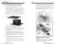
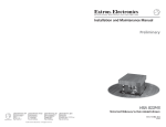
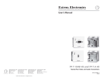
User’s Manual
HSA 822M
Motorized Hideaway Surface Access Enclosure
www.extron.com
Extron Electronics, USA
Extron Electronics, Europe
Extron Electronics, Asia
Extron Electronics, Japan
1230 South Lewis Street
Anaheim, CA 92805
USA
714.491.1500
Fax 714.491.1517
Beeldschermweg 6C
3821 AH Amersfoort
The Netherlands
+31.33.453.4040
Fax +31.33.453.4050
135 Joo Seng Road, #04-01
PM Industrial Building
Singapore 368363
+65.6383.4400
Fax +65.6383.4664
Daisan DMJ Building 6F
3-9-1 Kudan Minami
Chiyoda-ku, Tokyo 102-0074 Japan
+81.3.3511.7655
Fax +81.3.3511.7656
© 2004 Extron Electronics. All rights reserved.
68-617-03 Rev. A
Printed in the USA
10 04
Precautions
Safety Instructions • English
This symbol is intended to alert the user of important
operating and maintenance (servicing) instructions
in the literature provided with the equipment.
This symbol is intended to alert the user of the
presence of uninsulated dangerous voltage within
the product's enclosure that may present a risk of
electric shock.
Caution
Read Instructions • Read and understand all safety and operating
instructions before using the equipment.
Retain Instructions • The safety instructions should be kept for future
reference.
Follow Warnings • Follow all warnings and instructions marked on the
equipment or in the user information.
Avoid Attachments • Do not use tools or attachments that are not
recommended by the equipment manufacturer because they may be
hazardous.
Consignes de Sécurité • Français
Ce symbole sert à avertir l’utilisateur que la
documentation fournie avec le matériel contient des
instructions importantes concernant l’exploitation
et la maintenance (réparation).
Ce symbole sert à avertir l’utilisateur de la présence
dans le boîtier de l’appareil de tensions dangereuses
non isolées posant des risques d’électrocution.
Attention
Lire les instructions• Prendre connaissance de toutes les consignes de
sécurité et d’exploitation avant d’utiliser le matériel.
Conserver les instructions• Ranger les consignes de sécurité afin de
pouvoir les consulter à l’avenir.
Respecter les avertissements • Observer tous les avertissements et
consignes marqués sur le matériel ou présentés dans la documentation
utilisateur.
Eviter les pièces de fixation • Ne pas utiliser de pièces de fixation ni
d’outils non recommandés par le fabricant du matériel car cela
risquerait de poser certains dangers.
Sicherheitsanleitungen • Deutsch
Dieses Symbol soll dem Benutzer in der im
Lieferumfang enthaltenen Dokumentation
besonders wichtige Hinweise zur Bedienung und
Wartung (Instandhaltung) geben.
Dieses Symbol soll den Benutzer darauf aufmerksam
machen, daß im Inneren des Gehäuses dieses
Produktes gefährliche Spannungen, die nicht isoliert
sind und die einen elektrischen Schock verursachen
können, herrschen.
Achtung
Lesen der Anleitungen • Bevor Sie das Gerät zum ersten Mal verwenden,
sollten Sie alle Sicherheits-und Bedienungsanleitungen genau
durchlesen und verstehen.
Aufbewahren der Anleitungen • Die Hinweise zur elektrischen Sicherheit
des Produktes sollten Sie aufbewahren, damit Sie im Bedarfsfall darauf
zurückgreifen können.
Befolgen der Warnhinweise • Befolgen Sie alle Warnhinweise und
Anleitungen auf dem Gerät oder in der Benutzerdokumentation.
Keine Zusatzgeräte • Verwenden Sie keine Werkzeuge oder Zusatzgeräte,
die nicht ausdrücklich vom Hersteller empfohlen wurden, da diese eine
Gefahrenquelle darstellen können.
Instrucciones de seguridad • Español
Este símbolo se utiliza para advertir al usuario sobre
instrucciones importantes de operación y
mantenimiento (o cambio de partes) que se desean
destacar en el contenido de la documentación
suministrada con los equipos.
Este símbolo se utiliza para advertir al usuario sobre
la presencia de elementos con voltaje peligroso sin
protección aislante, que puedan encontrarse dentro
de la caja o alojamiento del producto, y que puedan
representar riesgo de electrocución.
Precaucion
Leer las instrucciones • Leer y analizar todas las instrucciones de
operación y seguridad, antes de usar el equipo.
Conservar las instrucciones • Conservar las instrucciones de seguridad
para futura consulta.
Obedecer las advertencias • Todas las advertencias e instrucciones
marcadas en el equipo o en la documentación del usuario, deben ser
obedecidas.
Evitar el uso de accesorios • No usar herramientas o accesorios que no
sean especificamente recomendados por el fabricante, ya que podrian
implicar riesgos.
Extron’s Warranty
Warning
Power sources • This equipment should be operated only from the power source
indicated on the product. This equipment is intended to be used with a main
power system with a grounded (neutral) conductor. The third (grounding) pin is
a safety feature, do not attempt to bypass or disable it.
Power disconnection • To remove power from the equipment safely, remove all
power cords from the rear of the equipment, or the desktop power module (if
detachable), or from the power source receptacle (wall plug).
Power cord protection • Power cords should be routed so that they are not likely to
be stepped on or pinched by items placed upon or against them.
Servicing • Refer all servicing to qualified service personnel. There are no userserviceable parts inside. To prevent the risk of shock, do not attempt to service
this equipment yourself because opening or removing covers may expose you to
dangerous voltage or other hazards.
Slots and openings • If the equipment has slots or holes in the enclosure, these are
provided to prevent overheating of sensitive components inside. These openings
must never be blocked by other objects.
Lithium battery • There is a danger of explosion if battery is incorrectly replaced.
Replace it only with the same or equivalent type recommended by the
manufacturer. Dispose of used batteries according to the manufacturer's
instructions.
Avertissement
Alimentations• Ne faire fonctionner ce matériel qu’avec la source d’alimentation
indiquée sur l’appareil. Ce matériel doit être utilisé avec une alimentation
principale comportant un fil de terre (neutre). Le troisième contact (de mise à la
terre) constitue un dispositif de sécurité : n’essayez pas de la contourner ni de la
désactiver.
Déconnexion de l’alimentation• Pour mettre le matériel hors tension sans danger,
déconnectez tous les cordons d’alimentation de l’arrière de l’appareil ou du
module d’alimentation de bureau (s’il est amovible) ou encore de la prise secteur.
Protection du cordon d’alimentation • Acheminer les cordons d’alimentation de
manière à ce que personne ne risque de marcher dessus et à ce qu’ils ne soient
pas écrasés ou pincés par des objets.
Réparation-maintenance • Faire exécuter toutes les interventions de réparationmaintenance par un technicien qualifié. Aucun des éléments internes ne peut être
réparé par l’utilisateur. Afin d’éviter tout danger d’électrocution, l’utilisateur ne
doit pas essayer de procéder lui-même à ces opérations car l’ouverture ou le
retrait des couvercles risquent de l’exposer à de hautes tensions et autres dangers.
Fentes et orifices • Si le boîtier de l’appareil comporte des fentes ou des orifices,
ceux-ci servent à empêcher les composants internes sensibles de surchauffer. Ces
ouvertures ne doivent jamais être bloquées par des objets.
Lithium Batterie • Il a danger d'explosion s'll y a remplacment incorrect de la
batterie. Remplacer uniquement avec une batterie du meme type ou d'un ype
equivalent recommande par le constructeur. Mettre au reut les batteries usagees
conformement aux instructions du fabricant.
Vorsicht
Stromquellen • Dieses Gerät sollte nur über die auf dem Produkt angegebene
Stromquelle betrieben werden. Dieses Gerät wurde für eine Verwendung mit
einer Hauptstromleitung mit einem geerdeten (neutralen) Leiter konzipiert. Der
dritte Kontakt ist für einen Erdanschluß, und stellt eine Sicherheitsfunktion dar.
Diese sollte nicht umgangen oder außer Betrieb gesetzt werden.
Stromunterbrechung • Um das Gerät auf sichere Weise vom Netz zu trennen,
sollten Sie alle Netzkabel aus der Rückseite des Gerätes, aus der externen
Stomversorgung (falls dies möglich ist) oder aus der Wandsteckdose ziehen.
Schutz des Netzkabels • Netzkabel sollten stets so verlegt werden, daß sie nicht
im Weg liegen und niemand darauf treten kann oder Objekte darauf- oder
unmittelbar dagegengestellt werden können.
Wartung • Alle Wartungsmaßnahmen sollten nur von qualifiziertem
Servicepersonal durchgeführt werden. Die internen Komponenten des Gerätes
sind wartungsfrei. Zur Vermeidung eines elektrischen Schocks versuchen Sie in
keinem Fall, dieses Gerät selbst öffnen, da beim Entfernen der Abdeckungen die
Gefahr eines elektrischen Schlags und/oder andere Gefahren bestehen.
Schlitze und Öffnungen • Wenn das Gerät Schlitze oder Löcher im Gehäuse
aufweist, dienen diese zur Vermeidung einer Überhitzung der empfindlichen
Teile im Inneren. Diese Öffnungen dürfen niemals von anderen Objekten
blockiert werden.
Litium-Batterie • Explosionsgefahr, falls die Batterie nicht richtig ersetzt wird.
Ersetzen Sie verbrauchte Batterien nur durch den gleichen oder einen
vergleichbaren Batterietyp, der auch vom Hersteller empfohlen wird. Entsorgen
Sie verbrauchte Batterien bitte gemäß den Herstelleranweisungen.
Advertencia
Alimentación eléctrica • Este equipo debe conectarse únicamente a la fuente/tipo
de alimentación eléctrica indicada en el mismo. La alimentación eléctrica de este
equipo debe provenir de un sistema de distribución general con conductor
neutro a tierra. La tercera pata (puesta a tierra) es una medida de seguridad, no
puentearia ni eliminaria.
Desconexión de alimentación eléctrica • Para desconectar con seguridad la
acometida de alimentación eléctrica al equipo, desenchufar todos los cables de
alimentación en el panel trasero del equipo, o desenchufar el módulo de
alimentación (si fuera independiente), o desenchufar el cable del receptáculo de
la pared.
Protección del cables de alimentación • Los cables de alimentación eléctrica se
deben instalar en lugares donde no sean pisados ni apretados por objetos que se
puedan apoyar sobre ellos.
Reparaciones/mantenimiento • Solicitar siempre los servicios técnicos de personal
calificado. En el interior no hay partes a las que el usuario deba acceder. Para
evitar riesgo de electrocución, no intentar personalmente la reparación/
mantenimiento de este equipo, ya que al abrir o extraer las tapas puede quedar
expuesto a voltajes peligrosos u otros riesgos.
Ranuras y aberturas • Si el equipo posee ranuras o orificios en su caja/alojamiento,
es para evitar el sobrecalientamiento de componentes internos sensibles. Estas
aberturas nunca se deben obstruir con otros objetos.
Batería de litio • Existe riesgo de explosión si esta batería se coloca en la posición
incorrecta. Cambiar esta batería únicamente con el mismo tipo (o su equivalente)
recomendado por el fabricante. Desachar las baterías usadas siguiendo las
instrucciones del fabricante.
Extron Electronics warrants this product against defects in materials and
workmanship for a period of three years from the date of purchase. In the event of
malfunction during the warranty period attributable directly to faulty workmanship
and/or materials, Extron Electronics will, at its option, repair or replace said products
or components, to whatever extent it shall deem necessary to restore said product to
proper operating condition, provided that it is returned within the warranty period,
with proof of purchase and description of malfunction to:
USA, Canada, South America,
and Central America:
Europe, Africa, and the Middle East:
Extron Electronics
1001 East Ball Road
Anaheim, CA 92805, USA
Extron Electronics, Europe
Beeldschermweg 6C
3821 AH Amersfoort
The Netherlands
Asia:
Japan:
Extron Electronics, Asia
135 Joo Seng Road, #04-01
PM Industrial Bldg.
Singapore 368363
Extron Electronics, Japan
Daisan DMJ Bldg. 6F,
3-9-1 Kudan Minami
Chiyoda-ku, Tokyo 102-0074
Japan
This Limited Warranty does not apply if the fault has been caused by misuse,
improper handling care, electrical or mechanical abuse, abnormal operating conditions
or non-Extron authorized modification to the product.
If it has been determined that the product is defective, please call Extron and ask for an
Applications Engineer at (714) 491-1500 (USA), 31.33.453.4040 (Europe), 65.6383.4400
(Asia), or 81.3.3511.7655 (Japan) to receive an RA# (Return Authorization number). This
will begin the repair process as quickly as possible.
Units must be returned insured, with shipping charges prepaid. If not insured, you
assume the risk of loss or damage during shipment. Returned units must include the
serial number and a description of the problem, as well as the name of the person to
contact in case there are any questions.
Extron Electronics makes no further warranties either expressed or implied with
respect to the product and its quality, performance, merchantability, or fitness for any
particular use. In no event will Extron Electronics be liable for direct, indirect, or
consequential damages resulting from any defect in this product even if Extron
Electronics has been advised of such damage.
Please note that laws vary from state to state and country to country, and that some
provisions of this warranty may not apply to you.
Table of Contents
Chapter 1 • Introduction .......................................................... 1-1
About the HSA 822M Hideaway Enclosures ............ 1-2
Features ...................................................................................... 1-4
Chapter 2 • Installation ............................................................. 2-1
Installation Overview .......................................................... 2-2
Preparing the Routing Template ................................... 2-4
Preparing the Table ................................................................. 2-5
Cabling and Installing the AAPs .................................... 2-7
Routing the AAP Cables and
Installing the Clamshell ..................................................... 2-9
Cabling the Enclosure ....................................................... 2-11
Bottom panel connectors and other features ................... 2-11
Cabling the RJ-45 connectors ............................................. 2-12
Cabling the control and status captive screw connector .. 2-13
Bezels ......................................................................................... 2-16
Chapter 3 • Maintenance and Modifications ............ 3-1
Replacing an AAP .................................................................. 3-3
Replacing the Bezels ............................................................ 3-5
Removing and Replacing the Enclosure .................... 3-7
Setting the Upper Limit Switch
(Elevated Platform Height) ............................................ 3-11
Setting the Lower Limit Switch
(Lowered Platform Height) ............................................ 3-12
Setting the Manual Release Switch ........................... 3-14
Safety Switch — Location Only .................................... 3-16
Replacing the Control Board Assembly and
Power Supply Assembly .................................................. 3-17
HSA 822M • Table of Contents
i
Table of Contents, cont’d
Appendix A • Reference Information ............................ A-1
Specifications ......................................................................... A-2
Part Numbers .......................................................................... A-4
HSA 822M .............................................................................. A-4
Included parts ....................................................................... A-4
Template, replacement parts, and accessories .................... A-4
Interface accessories ............................................................. A-5
Top Plate Dimensions ......................................................... A-6
HSA 822M cut-out template ................................................ A-7
Appendix B • Packaging for Shipment .......................... B-1
HSA 822M
1
Chapter One
Introduction
About the HSA 822M Hideaway Enclosures
Features
All trademarks mentioned in this manual are the properties of their respective owners.
68-617-03 Rev. A
Printed in the USA
10 04
ii
HSA 822M • Table of Contents
Introduction
About the HSA 822M Hideaway Enclosures
The Extron HSA 822M is a furniture-mounted, motorized
architectural solution for inconspicuous computer video
interface connector access and control.
The HSA 822M provides space for four double space (doubleheight) or eight single space Extron Architectural Adapter Plates
(AAPs), two standard grounded AC power receptacles, and four
RJ-45 (Category [CAT] 6) connectors (figure 1-1). The HSA is
available in a US version, with US power receptacles, and an
international version. Several different types of power
receptacles are available for the international version, including
UK, French, Israeli, Australian, Indian, European, and Swiss
receptacles.
Cables inside the enclosure route the front panel RJ-45 signal
lines to RJ-45 connectors on the underside of the enclosure.
With an optional conversion kit, one or more of the RJ-45 (data)
lines can be converted to an RJ-11 (telephone) line.
The functionality of the HSA 822M can be optimized with one
through four RGB 580xi AAPs connected to one through four
RGB 580xi Remote Interfaces (figure 1-2).
Projector
Extron
HSA 822M
INPUT
SELECT
COMPUTER
AUDIO
Closed
Open
Figure 1-1 — HSA 822M hideaway enclosure
The motorized action is controlled by contact closure. The
control mechanism uses discrete high or low signals to report
the HSA’s up or down position. Safety devices prevent injury
and equipment damage.
The installed enclosure fits nearly flush within a table or
podium top, storing the AAPs and connectors out of the way
and out of sight. To access the AAPs and connectors, the user
touches a button, makes a control system command, or presses
down on the top of the enclosure. A stepper motor slowly raises
the AAPs and connectors into view.
1-2
Extron
RGB 580xi
Remote Interface
Both Sides
INPUT
SELEC
T
COMP
AUDIO
UTER
Extron
HSA 822M
Surface Access
Enclosure
AUD
IO
INPU
ANA TS
LOG
CON
B TRO
A
C
D
L
E
VIDE
LEVEL
O OUTP
SOG
SERR
DDSP
PEAKIUT
NG
V-SYNC
NEG
WIDTH
COMPSYNC
SYNC
RGB
580
xi
Extron
RGB 580xi
The AAP spaces and RJ-45 connectors are arranged back-to
back, while the AC receptacles are back-to-back on the sides
perpendicular to the AAPs.
Figure 1-2 — HSA 822M and RGB 580xi
configuration
A cable inside the enclosure connects the user AC receptacles to
an IEC connector on the underside of the enclosure. The same
power cable supplies the stepper motor that drives the panel up
and down.
The HSA 822M is available in a variety of surface finishes,
including black anodized aluminum, brushed aluminum,
brushed brass, and polished aluminum.
HSA 822M • Introduction
HSA 822M • Introduction
1-3
Introduction, cont’d
Features
HSA 822M
•
UL listed
•
Easy access to connectors and controls
•
Durable motorized movement
•
Motion-limiting safety features to prevent injury and
equipment damage
•
A variety of available surface finishes
•
A variety of colors of included RJ-45 connector bezels:
black, red, blue, orange, gray, white, ivory, yellow, and
green
•
Compact size
•
Easy installation of up to four powered or passive double
space Extron AAPs
•
RJ-45 (CAT 5/6) network and data connections
•
Grounded AC plugs
2
Chapter Two
Installation
Installation Overview
Preparing the Routing Template
Preparing the Table
Cabling and Installing the AAPs
Routing the AAP Cables and Installing the Clamshell
Cabling the Enclosure
Bezels
1-4
HSA 822M • Introduction
Installation
Installation Overview
See figure 2-1 and the following steps to install the HSA 822M:
1
2
If desired, install the optional flexible conduit kit to
replace the removable AC power cord. Refer to the
Flexible Conduit Kit manual.
3
If you have an unprepared mounting template, prepare
the template. See Preparing the Routing Template on
page 2-4.
4
Cut a hole in the surface where the enclosure will be
installed. See Preparing the Table on page 2-5.
5
Run all cables necessary to support the AC, control and
status, and RJ-45 connectors and all planned AAP
connectors. Leave enough slack in the cables to connect
them to the underside of the enclosure or to the rear of the
AAPs before the AAPs are installed in the enclosure.
6
Turn off all of the equipment to be connected. Ensure that
the equipment connected to the RJ-45 connectors and the
connections for any AAPs are all turned off and
disconnected from the power source.
7
8
HSA 822
Enclosure
INP
SE UT
LE
CT
CO
MP
AU
UT
ER
DIO
Yellow Shipping
Restraints
REMOVE
Mounting
Surface
AAP Cables
If applicable, connect cables to the rear connectors on the
AAPs to be installed in the HSA 822M. Install the desired
AAPs on the AAP/RJ-45 panel of the enclosure. See
Cabling and Installing the AAPs on page 2-7.
Clamshell
Route and secure the AAP cables inside the enclosure,
install the clamshell, and then secure the AAP cables to
the clamshell. See Routing the AAP Cables and Installing the
Clamshell on page 2-9.
9
Connect the power, RJ-45, and control and status cables to
the underside of the enclosure. Remove the yellow
shipping restraint. See Cabling the Enclosure on page 2-11.
10
If not already accomplished, peel the protective coating
from the top surface and remove rubber strip that protects
the top surface’s flanged edges.
11
2-2
If desired, install the optional RJ-45 to RJ-11 conversion
kit(s) to replace one or more RJ-45 connectors with RJ-11
connectors. Refer to the RJ-45 to RJ-11 Conversion Kit
manual.
Motion Control
Connector
Network (TP)
Cables
IEC Power Cord
RJ-45 Connectors
Flat Washer
Full Thread
Mounting Bolts
Figure 2-1 — Mounting the HSA 822M enclosure
Connect power cords and turn on the devices that connect
to the surface access enclosure.
HSA 822M • Installation
HSA 822M • Installation
2-3
Installation, cont’d
Preparing the Routing Template
Preparing the Table
Extron provides a metal template, part #70-191-01, for the
HSA 822M and HSA 822 at no charge. Extron recommends
using this template as a guide to cut the hole in the table where
the HSA will be installed.
The metal routing template is reusable. Do not discard
this template when the installation is complete. Save it
for future HSA 822M installations.
1.
The preferred and recommended method for preparing the
table is to use the appropriate Extron metal routing template
and a router.
Alternatively, you can use a paper cut-out template
(see appendix A, Reference Information) and a sabre saw or
keyhole saw, but this method is not recommended.
Prepare the table as follows:
Cut 1/2" x 4" strips of soft, finished lumber long enough to
span the distance between the desired installation location
on the table or other mounting surface and the edges of
the table (figure 2-2).
CAUTION
Width of Mou
nting Surface
The routing templates for the various HSA models
are not interchangeable. If you use the wrong
template, you will cut an improperly-sized hole.
If you use a larger template than required, the cut
will result in gaps in the table surface on either side
of the enclosure.
Mounting
Surface
Edge
Wood
Strips
Minimum
4 Screws
The surfaces of the HSA enclosure have screws and
other protruding hardware that could damage fine
furniture. Do not rest the enclosure on unprotected
furniture.
Wood Strip
Height
4" / 10.2 cm
The metal routing template is reusable. Do not discard
this template when the installation is complete. Save it
for future HSA 822M or HSA 822 installations.
The HSA 822M mounts in exactly the same size hole as
the HSA 822 and uses the same metal mounting
template.
Routing Template
Mounting
Surface
Edge
Wood Thickness
0.5" / 1.3 cm
1.
Figure 2-2 — Prepared mounting template
These strips raise the routing template above the mounting
surface to provide room for the router’s collar, protect the
mounting surface, and extend the reach of the routing
template so that it can be clamped to the edge of the
surface.
2.
Using four or more short wood screws, secure the
mounting template to the lumber strips.
CAUTION
2-4
Do not allow the wood screws to protrude through
the bottom of the wooden strips. Protruding screws
will mar the table when the template is used.
HSA 822M • Installation
The opening in the table for the HSA 822M should
be cut only by licensed and bonded craftspeople.
Exercise care to prevent scarring or damaging the
furniture.
Locate the desired mounting location on the tabletop or
other installation surface. Mark the location.
CAUTION
Ensure that only the wooden strips contact the
furniture. Failure to do so may mar the furniture.
2.
Place the mounting template assembly on the table,
centered on the mounting location. Angle the template for
the optimum positioning. If necessary, use a square to
ensure that the template is properly positioned. Extron is
not responsible for improperly-positioned HSA products.
3.
Once the template assembly is positioned properly, use
C-clamps to secure the assembly to the table for routing as
shown in figure 2-3 on the next page.
HSA 822M • Installation
2-5
Installation, cont’d
7.
Carefully lower the HSA enclosure into the hole to test the
fit. If necessary, remove the enclosure and use a file or
rasp to enlarge or smooth the edges of the opening.
Cabling and Installing the AAPs
Extron’s various single space and double space AAP devices,
including the various RGB 580xi AAPs, can be mounted to the
HSA 822M. See appendix A, Reference Information, for
RGB 580xi AAP part numbers.
The screws for installing an AAP are built into its AAP/RJ-45
panel, so no additional screws are needed.
Ensure that AC power is disconnected before
servicing the HSA unit.
1.
Figure 2-3 — Cutting the opening with a router
Wear safety glasses when operating the router.
Failure to comply can result in eye injury.
4.
Using a router with a 5/8" (or 16 mm) outside diameter
guide bushing and a 1/2" (or 12 mm or 12.7 mm) diameter
straight router bit, carefully cut the opening in the table
surface (figure 2-3).
5.
Remove the C-clamps and the routing template.
The flanged edges of the top of the surface enclosure
are sharp when the HSA is not installed in a table.
Exercise caution when handling to prevent personal
injury.
CAUTION
6.
Remove the rubber strip that protects the top surface’s
flanged edges. If a sticky residue remains, remove it with
an appropriate metal cleaning product.
CAUTION
2-6
The flanged edges of the top of the surface enclosure
are bevelled to an ultra-fine thickness of less than
0.04 (4/100)" (approximately 1 mm). These edges
are soft and can be easily nicked or bent. Exercise
caution when handling and mounting the
enclosure. Mishandling can damage the appearance
of the enclosure.
Do not use isopropyl alcohol or other solvents to
clean the HSA. Strong solvents will ruin some
finishes.
HSA 822M • Installation
Remove the top and bottom screws on the right and left
sides of the AAP/RJ-45 panel (figure 2-4). Retain the
screws. Lift the panel away from the enclosure as far as
the connected cables allow and then allow the panel to
dangle, supported by its connected cables.
Remove two
screws ea. side.
Remove panel.
HS
A 82
2
Replacement Face Plate
Screws (4) Under Enclosure
Figure 2-4 — Removing the AAP/RJ-45 panels
The center screws on each side of the AAP/RJ-45 panel
do not fasten the AAP/RJ-45 panel in place. They secure
the AC power outlet.
Ensure that the edges of the AAP/RJ-45 panels do not
scratch the finished surface of the top panel flange when
removing the panels.
HSA 822M • Installation
2-7
Installation, cont’d
2.
3.
Cable the rear of the AAPs before fastening the AAPs to
the AAP/RJ-45 panel. Route the cables through the hole in
the underside of the surface mount enclosure and connect
them to the rear of the AAPs. If applicable, refer to the
cabling information in the documentation for the AAP.
Insert each of the AAP’s screws through the holes in the
AAP opening of the HSA AAP/RJ-45 panel. Secure each
AAP to the panel with the provided captive washers and
#4-40 nuts (figure 2-5).
#4-40 Nut w/ Captive
Washer
AAP/RJ-45
Panel
Routing the AAP Cables and
Installing the Clamshell
The AAP cables must have freedom of movement to permit
opening and closing the surface mount enclosure. At the same
time, they need to be restrained to prevent them from rubbing
against the edges of the enclosure cable access hole in the
underside of the surface mount enclosure. Rubbing against the
cable access hole edges can damage the cables. Route and
secure the AAP cables as follows:
1.
Manually open the top panel to extend the AAP cables to
their maximum pull.
2.
To prevent wear and tear or movement binding caused by
cable movement, secure the AAP cables inside the
enclosure. Use tie wraps to secure the cables to the tiedowns accessible through the cable access holes
(figure 2-6).
Cable
IN
SE PUT
LE
CT
HS
CO
AU
MP
UTE DIO
R
A8
22M
RGB 580xi SI AAP
Figure 2-5 — Mounting an AAP on the AAP/RJ-45
panel
4.
Replace the AAP/RJ-45 panel in the surface mount
enclosure and secure it in place with the screws removed
in step 1. If you lose an AAP/RJ-45 panel screw, four
spare screws are stored in the underside of the enclosure
(figure 2-8 on page 2-11, item 5 ).
Figure 2-6 — Cable tie-downs inside the HSA
(seen from underneath)
2-8
HSA 822M • Installation
HSA 822M • Installation
2-9
Installation, cont’d
3.
From the underside of the table, bolt the clamshell to the
enclosure with two bolts of optimum length (included)
(see figure 2-1 on page 2-3).
4.
Experiment with AAP cable positioning between the
enclosure and the clamshell to ensure that the cables do
not rub against the edges of the AAP cable access hole and
to ensure that the cable pull does not restrict the
movement of the top panel. Figure 2-7 shows the cables
routed to the side, which proved effective in tests at Extron.
Cabling the Enclosure
Bottom panel connectors and other features
2
4
8
6
1
5
1
Secure the AAP cables at the circled location.
Figure 2-7 — HSA 822M AAP cable routing in the
clamshell
5.
Use tie wraps to secure the AAP cables to the tie-down
holes in the clamshell shown on figure 2-7.
3
4
8
7
Figure 2-8 — HSA 822M underside features
1
RJ-45 connectors — See Cabling the RJ-45 connectors on page 2-12.
2
AC power connector — Plug a standard IEC power cord into
this connector to connect the enclosure to the appropriate power
source:
• 125 VAC, 60 Hz, 5 A (US domestic version)
• 220-240 V, 50/60 Hz, 5 A (international versions)
3
Control and status captive screw connector — See Cabling the
control and status captive screw connector on page 2-13.
4
Cable access holes*
5
Spare AAP/RJ-45 panel screws*
6
Power supply assembly*
7
Control board assembly*
8
Cable tie-downs*
Items marked with an asterisk (*) have limited
accessibility once the clamshell is installed.
2-10
HSA 822M • Installation
HSA 822M • Installation
2-11
Installation, cont’d
Cabling the RJ-45 connectors
Plug one end of a terminated CAT 5 or CAT 6 twisted pair (TP)
cable into each of these RJ-45 female connectors. Connect the
other end to an appropriate telecommunications or data
network device or to an Extron TP product.
Cabling the control and status captive screw
connector
Plug one end of the control cable(s) into this 10-pole captive
screw connector. Connect the other end of the cable(s) to a
control and/or monitoring system. The following table
identifies the signals on each pin of the connector.
An RJ-11 (telephone) plug can be connected to the RJ-45
jack.
The bottom RJ-45 connectors match up with the AAP/RJ-45
panel RJ-45 connectors as shown in figure 2-9. For example,
match the AAP/RJ-45 panel RJ-45 connector A1 with the
underside RJ-45 connector A1, match A2 with A2, and so forth.
Control and status connector pinout
Down
Stop
B2
B1
Pin Definition
1 Up (control)
B2
A2
Figure 2-9 — HSA 822M RJ-45 connectors
If necessary, have a qualified service person replace the
connector icon on the AAP/RJ-45 panel by prying the old icon
off of the connector plug-in with a Tweeker or small screwdriver
(see figure 2-10) and snapping a new icon in place.
2
Down (control)
3
Stop (control)
4
5
Gnd
Enable
6
Up (status)
7
Down (status)
8
9
Gnd
Power (status)
6
7
Definition
Momentary
contact closure
Momentary
contact closure
Momentary
contact closure
Gnd
Contact closure
Grounded/
open
Grounded/
open
Gnd
Grounded/
open
Icon Labels
10 Gnd
5
Gnd
8
9 10
Pwr status
Up
4
Down status
3
Up status
2
Enable
1
B1
A1
A2
A1
Cut the tie wraps and remove the yellow shipping
restraint before testing the motorized mechanism.
CAUTION
Explanation
Short to ground to raise
(open) the top panel.
Short to ground to lower
(shut) the top panel.
Short to ground to stop
the top panel's motion.
Ground
Short to ground to enable
activating the motor by
pressing on the top panel.
Grounded = up
Open = down or in motion
Grounded = down
Open = up or in motion
Ground
Grounded = AC power is
applied.
Open = No power is
applied.
Ground
Figure 2-10 — Changing the connector icon
2-12
HSA 822M • Installation
HSA 822M • Installation
2-13
Installation, cont’d
If connected to the power status pin, the LED is lit so long as
power is applied to the HSA.
Figure 2-13 shows a typical locally-constructed contact closure
control and LED indication device.
1
2
3
4
5
7
6
Pwr status
Stop
Down
Up
+12 V
Down status
HSA 822M
Up status
Enable
Figure 2-11 shows the function of the HSA’s status pins (6 [up],
7 [down], and 9 [power]). When a status condition is met, the
switch closes, shorting the status pin to ground, pulling it low.
When a status condition is not met, the switch opens, floating
the status pin. Status pins 6, 7, and 9 can sink +5 VDC to
+12 VDC, 500 mA, maximum.
8
9 10
STATUS
PIN
CTL
BRD
SW 1
GND
Figure 2-11 — Equivalent status pin circuit
+-
Figure 2-12 expands upon figure 2-11 to show suggested
circuitry to display the HSA’s status. In this figure, the LED
lights for as long as the status pin is pulled low (the switch is
shorted [closed]).
HSA 822M
+12 V
PWR SUP
Figure 2-13 — Typical local control device
Figure 2-14 shows the HSA connected to an Extron MLC 226
MediaLink™ Controller. The status pin can trigger the MLC’s
digital input.
470
MLC 226
HSA 822M
LED
+5 V
STATUS
PINS
CTL
BRD
EXT
SRC
+3.3 V
+12 V
+12 V
2K
SW 1
GND
CTL
BRD
STATUS
PINS
DIGITAL
INPUT
GND
GND
SW 2
CTL
SW 1
NOTE This drawing shows a standard +5 V power supply. +12 V is another
standard power supply that can be used in this circuit. If you use a
+12 V supply, use a 2k ohm resistor in place of the 470 ohm resistor shown.
Figure 2-12 — Typical status display circuit
If connected to a position (up or down) status pins, the LED
lights when the HSA platform is in the stated position. The LED
is unlit when the platform is in motion or in the opposite
position. Under no circumstances should both position LEDs
light simultaneously.
2-14
HSA 822M • Installation
Figure 2-14 — Typical MediaLink control device
The MLC’s pull-up resistor to 3.3 VDC must be
activated (the MLC’s switch 2 closed). Refer to the
MLC 226 product manual.
The flex I/O port on an Extron IP Link™ Ethernet
Control Interface can be used in place of the MLC 226
and its digital input port.
HSA 822M • Installation
2-15
Installation, cont’d
Bezels
The HSA 822M ships with RJ-45/RJ-11 connector bezel plug-ins
in a variety of colors and a black, blank bezel.
Bezel
To change to a different color RJ-45 connector
bezel or if an RJ-45 connector is not needed or
desired, replace the connector bezel plug-in on
the AAP/RJ-45 panel with a bezel of a different
color or a blank plug-in. See Replacing the Bezels
in chapter 3.
If no RJ-45 connector is desired, snap
the interior RJ-45 cable onto the rear of
the blank bezel plug-in (shown at
right) to hold it conveniently out of the
way. Retain the removed connector
bezel plug-in for any possible later
use.
Blank Bezel
Plug-in in AAP
Panel
HSA 822M
3
Chapter Three
Maintenance and Modifications
Replacing an AAP
Replacing the Bezels
Removing and Replacing the Enclosure
Setting the Upper Limit Switch (Elevated Platform Height)
Setting the Lower Limit Switch (Lowered Platform Height)
Setting the Manual Release Switch
Safety Switch — Location Only
Replacing the Control Board Assembly and Power Supply Assembly
2-16
HSA 822M • Installation
.
Maintenance and Modifications
This chapter provides the following procedures:
Maintenance procedures marked with an asterisk (*)
require removing the HSA 822M from the table.
•
Replacing an AAP
•
Replacing the bezels
•
Removing and replacing the HSA in the table (for other
maintenance procedures)*
•
Adjusting the upper-level and lower-level stop point and
the manual mode release point*
•
Replacing the power supply assembly and the control
board assembly*
Replacing an AAP
Replace one or more AAPs as follows:
1.
Ensure that AC power is disconnected before
servicing the HSA unit.
When AC power is removed, the platform may sink
partially down into the HSA.
2.
Figure 3-1 shows the underside of the enclosure and many of
the maintenance-related features.
4*
4
Activate the motor to raise the platform, and then
disconnect the AC power.
Remove and retain the top and bottom screws on the right
and left sides of the AAP/RJ-45 panel (figure 3-2). Lift the
panel away from the enclosure as far as the connected
cables allow and then allow the panel to dangle,
supported by its connected cables.
X
Remove two
screws ea. side.
1
5
9
3
8
6
IN
SE PUT
LE
CT
8
3
5
2
MPU
TE
AU
DIO
R
HS
A 82
2M
7
4
4
X
4
X=Do not remove.
Figure 3-1 — HSA 822M maintenance features
1
Control board assembly
6
Spare AAP/RJ-45 panel screws
2
Power supply assembly
7
AC power connector
3
Cable access holes
8
RJ-45 connector
4
Assembly screws*
9
Control and status connector
5
Cable tie-downs
X
Structural screws —
Do not remove.
The screws indicated by an asterisk (*) on figure 3-1 are
accessible from the top (inside the enclosure).
3-2
Remove panel.
CO
HSA 822M • Maintenance and Modifications
Figure 3-2 — Removing the AAP/RJ-45 panel
The center screws on each side of the AAP/RJ-45 panel
do not fasten the AAP/RJ-45 panel in place. They secure
the AC power outlet.
CAUTION
3.
Ensure that the edges of the AAP/RJ-45 panels do
not scratch the finished surface of the top panel
flange or the furniture in which the HSA 822M is
installed when removing the panels.
Disconnect any cables from the rear of the AAP(s) that are
being replaced.
HSA 822M • Maintenance and Modifications
3-3
Maintenance and Modifications, cont’d
4.
If an AAP cable is no longer required in your system, on
the underside of the clamshell, cut the tie wraps that route
the AAP cables out of the way.
5.
If an AAP cable is no longer required in your system,
on the underside of the table, remove the two bolts
(shown at right) that secure the clamshell to the surface
mount enclosure and remove the clamshell.
6.
If an AAP cable is no longer required in your system,
from the underside of the enclosure, reach into the
cable access holes (figure 3-1 on page 3-2, item 3 ), and
cut the tie wraps ( 5 ) that route the AAP cables and
network (CAT 6) cables inside the enclosure.
7.
If an AAP cable is no longer required in your system,
carefully pull the cable through and out the bottom of the
surface mount enclosure and the clamshell.
8.
Remove the AAP(s) that you no longer want from the
AAP/RJ-45 panel by unscrewing the nuts on the rear of
the AAP/RJ-45 panel that secure the AAPs in place.
9.
Cable the rear of the AAP(s) to be installed before
attaching the AAP(s) to the enclosure. Route the cables
through the hole in the underside of the surface mount
enclosure and connect them to the rear of the AAP(s). If
applicable, refer to the cabling information in the
documentation for the AAP.
10.
Insert each AAP’s screws through the holes in the AAP
opening of the AAP/RJ-45 panel. Secure each AAP to the
panel with the provided captive washers and #4-40 nuts
(figure 3-3).
11.
Replace the AAP/RJ-45 panel in the surface mount
enclosure and secure them in place with the screws
removed in step 2. If you lose an AAP/RJ-45 panel screw,
four spare screws are stored in the underside of the
enclosure (figure 3-1 on page 3-2, item 6 ).
12.
If you replaced an AAP cable, to prevent wear and tear
caused by cable movement, secure the AAP cables
underneath the table. See Routing the AAP Cables and
Installing the Clamshell on page 2-9.
Replacing the Bezels
The HSA 822M ships with RJ-45 connector bezel plug-ins in a
variety of colors and a black, blank bezel. Replace a bezel as
follows:
1.
The center screws on each side of the AAP/RJ-45 panel
do not fasten the AAP/RJ-45 panel in place. They secure
the AC power outlet.
Ensure that the edges of the AAP/RJ-45 panels do not
scratch the finished surface of the top panel flange when
removing the panels.
2.
With a tweeker, push down on and
gently twist on the front of each RJ-45
connector detent to disconnect the
connector from the rear of the AAP/RJ-45
panel plug-in.
3.
Pinch the top and bottom bezel detents
together and push the bezel through the
AAP/RJ-45 panel.
#4-40 Nut w/ Captive
Washer
AAP/RJ-45
Panel
Remove and retain the top and bottom screws on the right
and left sides of the AAP/RJ-45 panel (figure 3-2). Lift the
panel away from the enclosure as far as the connected
cables allow and then allow the panel to dangle,
supported by its connected cables.
Cable
IN
SE PUT
LE
CT
HS
CO
AU
MP
UTE DIO
R
A8
22M
RGB 580xi SI AAP
Figure 3-3 — Mounting an AAP device
3-4
HSA 822M • Maintenance and Modifications
HSA 822M • Maintenance and Modifications
3-5
Maintenance and Modifications, cont’d
4.
Snap a replacement bezel in place. If necessary, replace the
connector icon by prying the old icon off of the connector
plug-in with a tweeker (figure 3-4) and snapping a new
icon in place.
Removing and Replacing the Enclosure
Many maintenance procedures require removing the HSA 822M
from the table. Remove and replace the surface mount
enclosure as follows:
1.
Activate the motor to raise the platform and then
disconnect the AC power.
Ensure that AC power is disconnected before
servicing the HSA unit.
Icon Labels
When AC power is removed, the platform may sink
partially down into the HSA.
Figure 3-4 — Changing the connector icon
5.
Snap the interior RJ-45 cable
connectors onto the rear of the
replacement RJ-45 AAP panel
bezel plug-ins.
6.
Replace the AAP/RJ-45 panel in
RJ-45 Bezel
the surface mount enclosure and Plug-in in AAP
Panel
secure it in place with the screws
removed in step 1. If you lose an
AAP/RJ-45 panel screw, four spare screws are stored in
the underside of the enclosure (figure 3-1 on page 3-2,
item 6 ).
2.
On the underside of the clamshell, cut the tie wraps that
route the AAP cables out of the way.
3.
For both AAP/RJ-45 panels, remove the top and bottom
screws on the right and left sides of the panel (figure 3-2).
Retain the screws. Lift the panels away from the enclosure
as far as the connected cables allow and then allow the
panels to dangle, supported by their connected cables.
The center screws on each side of the AAP/RJ-45 panel
do not fasten the AAP/RJ-45 panel in place. They secure
the AC power outlet.
CAUTION
4.
Ensure that the edges of the AAP/RJ-45 panels do
not scratch the finished surface of the top panel
flange or the furniture in which the HSA 822M is
installed when removing the panels.
To ensure that you remate RJ-45 connectors in the proper
position when the maintenance is complete, tag the
internal CAT 6 cables to define their installation location
(top or bottom and side A or B).
Also tag the side of the enclosure itself (A or B).
3-6
HSA 822M • Maintenance and Modifications
5.
With a tweeker, inside the AAP/RJ-45
panels, push down on and gently twist
on the front of each RJ-45 connector
detent to disconnect the connector from
the rear of the AAP/RJ-45 panel plug-in.
6.
Disconnect any cables from the rear of
the existing AAPs.
7.
Set the AAP/RJ-45 panels aside.
8.
Disconnect the IEC power cord, the RJ-45
connectors, and the control and status
connector (figure 3-1 on page 3-2, items 7 , 8 , and
9 ) from the connectors on the underside of the HSA.
HSA 822M • Maintenance and Modifications
3-7
Maintenance and Modifications, cont’d
9.
On the underside of the table, remove the two bolts that
secure the clamshell to the surface mount enclosure and
remove the clamshell (figure 3-5).
10.
From the underside of the enclosure, reach into the cable
access holes (figure 3-1 on page 3-2, item 3 ), and cut the
tie wraps ( 5 ) that route the AAP cables and network
(CAT 6) cables inside the enclosure. Carefully pull the
cables through and out the bottom of the HSA.
11.
Lift the enclosure out of the table.
HSA 822
Enclosure
INP
SE UT
LE
CT
CO
MP
AU
UT
ER
The flanged edges of the top of the surface enclosure
are sharp when the HSA is removed from the table.
Exercise caution when handling to prevent personal
injury.
DIO
Yellow Shipping
Restraints
CAUTION
REMOVE
The flanged edges of the top of the surface enclosure
are bevelled to an ultra-fine thickness of less than
0.04 (4/100)" (approximately 1 mm). These edges
are soft and can be easily nicked or bent. Exercise
caution when handling and mounting the
enclosure. Mishandling can damage the appearance
of the enclosure.
The surfaces of the HSA enclosure have screws and
other protruding hardware that could damage fine
furniture. Do not rest the enclosure on unprotected
furniture.
Mounting
Surface
12.
Remove and retain the four screws in the corners of each
side’s surface of the enclosure shroud “cube” (figure 3-6).
Remove the two halves of the shroud.
AAP Cables
HSA 822M
Enclosure
IN
SE PUT
LE
CT
CO
MP
AU
UT
ER
DI
O
Clamshell
Remove (16)
screws.
Motion Control
Connector
Shroud
Network (TP)
Cables
IEC Power Cord
RJ-45 Connectors
Flat Washer
Full Thread
Mounting Bolts
Figure 3-6 — Removing the shroud
Figure 3-5 — Removing the HSA 822M from the table
3-8
HSA 822M • Maintenance and Modifications
HSA 822M • Maintenance and Modifications
3-9
Maintenance and Modifications, cont’d
You do not need to remove the screws in the center of two
of the sides. They do not secure the shroud in any way;
rather, they provide structural support to the enclosure.
13.
Perform the desired maintenance procedure.
14.
Secure the two shroud halves to the enclosure frame with
the eight screws per shroud half (four per side) removed in
step 2. Orient the shroud halves such that the vertical
column of center holes align with the column of screw
inserts on the vertical slides.
15.
Carefully lower the HSA enclosure into the table opening.
16.
Cable the rear of the AAPs that are fastened to the
AAP/RJ-45 panel. Route the cables through the hole in
the underside of the surface mount enclosure and connect
them to the rear of the AAPs. If applicable, refer to the
cabling information in the documentation for the AAP.
17.
Snap the interior RJ-45 cable
connectors onto the rear of the
RJ-45 AAP panel bezel plug-ins in
the locations identified by the
tags.
18.
19.
20.
Setting the Upper Limit Switch
(Elevated Platform Height)
This switch’s position is properly set in the factory.
The upper limit switch sets the stop point for the raised
platform. If the switch is set too low, the platform does not rise
high enough. If the switch is set too high, the motor attempts to
raise the platform past the mechanical stop and then lowers the
platform to the recessed position. Set the platform’s height as
follows:
1.
Remove the surface mount enclosure from the table. See
Removing and Replacing the Enclosure, steps 1 through 12.
Place the enclosure on a horizontal surface. Let the AC
and control and status connectors (figure 3-1 on page 3-2,
items 7 and 9 ) hang off the edge of the surface so that
they are accessible.
2.
Plug in AC power and the control and status device.
3.
Activate the motor to raise the platform. Leave AC power
applied to the HSA.
Do not reach tools or your hands into the area
behind the AC connectors or into the vicinity of the
power supply.
RJ-45 Bezel
Plug-in in AAP
Replace the AAP/RJ-45 panel in
Panel
the surface mount enclosure and
secure it in place with the screws
removed in step 1. If you lose an AAP/RJ-45 panel screw,
four spare screws are stored in the underside of the
enclosure (figure 3-1 on page 3-2, item 6 ).
To prevent wear and tear caused by cable movement,
secure the AAP cables underneath the table. See
page 2-9, Routing the AAP Cables and Installing the Clamshell.
Connect the IEC power cord, the RJ-45 connectors, and the
control and status connector (figure 3-1 on page 3-2,
items 7 , 8 , and 9 ) to the connectors on the underside of
the HSA.
4.
Locate the upper limit switch assembly (figure 3-7) inside
the enclosure.
Upper Limit
Switch
Assembly
Power
Supply
Control
Board
Figure 3-7 — Location of upper limit switch assembly
(seen from the side)
3-10 HSA 822M • Maintenance and Modifications
HSA 822M • Maintenance and Modifications
3-11
Maintenance and Modifications, cont’d
5.
Loosen the upper limit
lock nut.
6.
Rotate the upper limit
set screw:
Upper Limit
Switch
Switch (Hidden)
Actuator
Clockwise to lower
the upper limit of
platform motion.
Counterclockwise to raise
the upper limit of platform
motion.
2.
Upper Limit
Lock Nut
Lower Limit
Set Screw
Upper Limit
Set Screw
Lower Limit
Switch
Adjustments do not take affect immediately. You must
use the motor mechanism to lower and raise the platform
to see the affect of your adjustment.
7.
Lower and raise the platform to check the adjusted height.
If necessary, repeat step 6.
8.
Tighten the upper limit lock nut.
9.
Disconnect the power and control and status connectors.
10.
Reinstall the surface mount enclosure. See Removing and
Replacing the Enclosure, steps 14 through 20.
Setting the Lower Limit Switch
(Lowered Platform Height)
This switch’s position is properly set in the factory.
Control
Board
NOTE RJ-45 connectors are removed for visibility.
Figure 3-8 — Location of lower limit switch assembly
(seen from the side)
The lower limit switch looks similar to, but not exactly
like the upper limit switch shown on page 3-12.
3.
Loosen the lower limit lock nut.
4.
Rotate the lower limit set screw:
Clockwise to raise the stop point of the retracted platform.
The lower limit switch sets the stop point for the lowered
platform. If the switch is set too high or low, the retracted
platform is not flush with the surrounding flange. Set the
retracted height of the platform as follows:
1.
Remove the surface mount enclosure from the table. See
Removing and Replacing the Enclosure, steps 1 through 12.
Place the enclosure on a horizontal surface. To protect the
finish, place the enclosure on a soft cloth. Let the AC and
control and status connectors (figure 3-1 on page 3-2, items
7 and 9 ) hang off the edge of the surface so that they are
accessible.
3-12 HSA 822M • Maintenance and Modifications
Locate the lower limit switch assembly (figure 3-8) inside
the enclosure.
Counterclockwise to lower the stop point of the retracted
platform.
Adjustments do not take affect immediately. You must
use the motor mechanism to raise and lower the platform
to see the affect of your adjustment.
5.
Plug in AC power and the control and status device.
Do not reach tools or your hands into the area
behind the AC connectors or into the vicinity of the
power supply.
6.
Raise and lower the platform to check the adjusted height.
If necessary, repeat step 4.
7.
Tighten the lower limit lock nut.
8.
Disconnect the power and control and status connectors.
9.
Reinstall the surface mount enclosure. See Removing and
Replacing the Enclosure, steps 14 through 20.
HSA 822M • Maintenance and Modifications
3-13
Maintenance and Modifications, cont’d
4.
Setting the Manual Release Switch
This switch’s position is properly set in the factory.
The manual release switch sets the amount of pressure needed
to activate the press-to-activate feature. If the switch is set too
low, you may have to push too hard on the platform. If the
switch is set too high, the drive mechanism may activate
sporadically. Set the height of the platform as follows:
It is unlikely that the position of the manual release
switch will ever need adjustment.
1.
Remove the surface mount enclosure from the table. See
Removing and Replacing the Enclosure, steps 1 through 12.
Place the enclosure on a horizontal surface. To protect the
finish, place the enclosure on a soft cloth. Let the AC and
control and status connectors (figure 3-1 on page 3-2, items
7 and 9 ) hang off the edge of the surface so that they are
accessible.
2.
Plug in AC power and the control and status device.
3.
Activate the motor to raise the platform. Leave AC power
applied to the HSA.
Do not reach tools or your hands into the area
behind the AC connectors or into the vicinity of the
power supply.
Locate the manual release switch assembly (figure 3-9)
inside the enclosure.
Manual
Release
Switch
Assembly
Lower
Limit
Set Screw
Manual
Release
Switch
RJ-45
Connectors
Manual
Release
Set Screw
Figure 3-9 — Location of manual release switch
assembly (seen from the side)
The manual release switch looks similar to, but not
exactly like the upper limit switch shown on page 3-12.
5.
Loosen the manual release lock nut.
6.
Rotate the manual set screw:
Clockwise to make the manual release more sensitive.
Counterclockwise to make the manual release less
sensitive (you must push harder to activate the press-torelease feature).
7.
Press on the platform to activate the press-to-activate
function. If necessary, repeat step 6.
Pin 5 of the control and status connector (figure 3-1 on
page 3-2, item 9 ) must be tied to ground to enable the
press-to-activate function.
3-14 HSA 822M • Maintenance and Modifications
8.
Tighten the manual release lock nut.
9.
Disconnect the power and control and status connectors.
10.
Reinstall the surface mount enclosure. See Removing and
Replacing the Enclosure, steps 14 through 20.
HSA 822M • Maintenance and Modifications
3-15
Maintenance and Modifications, cont’d
Safety Switch — Location only
The safety switch (figure 3-10) stops the downward motion of
platform when it encounters an obstruction to its smooth
operation. If an obstruction is present that blocks the platform’s
travel, the stepper motor’s carriage lifts and activates the safety
switch. The HSA’s motor logic automatically reverses the
platform’s motion and raises the platform to the upper position.
The carriage typically reverses with less than twelve pounds of
pressure applied to the obstruction.
Replacing the Control Board Assembly and
Power Supply Assembly
If they fail, the control board assembly (figure 3-1 on page 3-2,
1 ) and the power supply assembly ( 2 ) can be replaced as
follows:
1.
Remove the surface mount enclosure from the table. See
Removing and Replacing the Enclosure, steps 1 through 12.
Place the enclosure on a horizontal surface. To protect the
finish, place the enclosure on a soft cloth.
2.
From the underside of the enclosure, reach into the cable
access holes (figure 3-1 on page 3-2, item 3 ), and cut the
tie wraps 5 that route the AAP cables and network
(CAT 6) cables inside the enclosure.
3.
Remove the three screws (figure 3-1 on page 3-2, item 4 )
that secure the assembly to be replaced to the underside of
the enclosure.
Stepper
Motor and
Carriage
Assembly
For the control board assembly, screws indicated by an
asterisk (*) on figure 3-1 are accessible from the top
(inside the enclosure).
Do not remove screw X (figure 3-1 on page 3-2).
This screw does not secure the power supply assembly in
any way; rather, it provides structural support to the
enclosure.
Safety
Switch
Figure 3-10 — Location of the safety switch
(seen from the side)
4.
Remove all connectors from the assembly to be replaced.
5.
Remove the assembly from the enclosure.
6.
Secure the replacement assembly in the enclosure with the
screws removed in step 3.
7.
Reconnect all connectors removed in step 4.
8.
Retie all of the network (CAT 6) and AAP cables removed
in step 2 to the tie-downs (figure 3-1 on page 3-2, item 5 )
on the assembly that was replaced.
9.
Reinstall the surface mount enclosure. See Removing and
Replacing the Enclosure, steps 14 through 20.
The safety switch cannot be adjusted.
3-16 HSA 822M • Maintenance and Modifications
HSA 822M • Maintenance and Modifications
3-17
Maintenance and Modifications, cont’d
HSA 822M
A
Appendix A
Reference Information
Specifications
Part Numbers
Top Plate Dimensions
3-18 HSA 822M • Maintenance and Modifications
Reference Information
Specifications
Control/remote
Contact closure ..............
(1) 3.5 mm female captive screw connector, 10
pole
Contact closure/level pin configuration
Pin 1 = up, pin 2 = down, pin 3 = stop,
pin 5 = enable push operation, pin 6 = status up,
pin 7 = status down, pin 9 = status power,
pins 4, 8, and 10 = ground
A
General
Power ..............................
100 VAC to 240 VAC, 50/60 Hz, 25 watts,
internal, autoswitchable
Temperature/humidity . Storage: -40 to +158°F (-40 to +70°C) /
10% to 90%, noncondensing
Operating: +32 to +122°F (0 to +50°C) /
10% to 90%, noncondensing
Rack mount .................... No, but furniture mountable
Enclosure type ............... Metal
Enclosure approximate dimensions
CAUTION
Use the appropriate metal Extron routing template or refer to
the surface cutout dimensions here before cutting a hole in the
furniture or other surface. Pay special attention to the direction
the unit will face; the unit’s AAP and connector access side is
underlined. Extron is not responsible for miscut mounting
holes.
C
B
Figure A-1 — Clamshell dimensions
Product/shipping weight .........
Listings ........................................
Compliances ...............................
MTBF (stepper motor) ...............
Warranty .....................................
10.0 lbs (4.5 kg)/17 lbs (8 kg)
UL, CUL
CE
100,000 cycles
3 years parts and labor
Specifications are subject to change without notice.
Top plate (outer rim) ........................... 8.470" W x 8.750" D
(21.51 cm W x 22.23 cm D)
Top plate (vertically lifting plate) ..... 6.220" W x 6.500" D
(15.80 cm W x 16.51 cm D)
Surface cutout ...................................... 7.90" ±0.0325" W (AAP access from
front and back) x 8.250" ±0.0325" D
(20.07 ±0.083 cm W x 20.96 ±0.083 cm D)
Clamshell (figure A-1) ........................ A = 7.24" (18.39 cm)
B = 8.25" (21.0 cm)
C = 10.98" (27.89 cm)
A-2
HSA 822M • Reference Information
HSA 822M • Reference Information
A-3
Reference Information, cont’d
Interface accessories
Part Numbers
Accessory
HSA 822M
HSA 822M
Part number
HSA 822M US Enclosure (black anodized)
60-719-0A
HSA 822M International Enclosure (black anodized)
60-719-nn
The USA version of the HSA 822M is also available in
brushed aluminum, polished aluminum, and brushed
brass finishes. Visit the Extron web site,
www.extron.com for more part numbers.
For the international versions, the nn in the part number
identifies the AC power connector and finish (black
anodized, brushed aluminum, polished aluminum, and
brushed brass). Specify the desired power connector and
finish when ordering.
Part number
RGB 580xi
60-362-01
RGB 580xi AAP 3' (black)
70-128-02
RGB 580xi AAP 6' (black)
70-129-02
RGB 580xi AAP 12' (black)
70-130-02
RGB 580xi I AAP 12' (black)
70-133-02
RGB 580xi S AAP 3' (black)
70-134-02
RGB 580xi S AAP 6' (black)
70-135-02
RGB 580xi SI AAP 3' (black)
70-137-02
RGB 580xi SI AAP 6' (black)
70-138-02
Included parts
Part
Part number
HSA 822M Hideaway Products manual
Snap-in icon inserts
RJ-45 connector bezel plug-in inserts
(assorted colors and blank)
10-pin captive screw connector
100-319-11
1/4 - 20, 1", 1 ½", 2", 2 ½" full thread bolts
-or- M6 x 65 mm, 50 mm, 40 mm, 25 mm full thread bolts
IEC power cord (US model only)
Template, replacement parts, and accessories
Part
Part number
HSA 822 routing template
70-191-01
The HSA 822M mounts in exactly the same size hole as
the HSA 822 and uses the same metal mounting
template.
A-4
HSA 822M/MS power supply assembly
70-461-01
HSA 822M/MS control board assembly
70-462-01
HSA 822 RJ-11 cable kit
70-226-01
HSA 822 flexible conduit adapter kit
70-228-01
HSA 822M • Reference Information
HSA 822M • Reference Information
A-5
Reference Information, cont’d
HSA 822M cut-out template
Top Plate Dimensions
The preferred and recommended method for cutting the table is
to use the metal routing template (figure A-2 and chapter 2,
Installation) and a router. The template, part #70-191-01, is
available at no cost.
Cut-Out Template for Extron's
HSA 822M
User Access (Connectors and AAP Openings)
8.470" (21.51 cm)
6.220" (15.80 cm)
7.900 + 0.0325"
(20.07 + 0.083 cm)
8.750"
(22.23 cm)
6.500"
(16.51 cm)
USER ACCESS
USER ACCESS
SURFACE CUT-OUT
AREA = 7.900 + 0.0325"
(20.07 + 0.083 cm) x
8.250 + 0.0325"
(20.96 + 0.083 cm)
8.250 + 0.0325"
(20.96 + 0.083 cm)
EXTRON ELECTRONICS
Figure A-2 — HSA 822 metal routing template
The HSA 822M mounts in exactly the same size hole as
the HSA 822 and uses the same metal mounting
template.
If you choose not to use Extron’s metal routing template, the
cut-out template (figure A-3 on the next page) will help you
properly prepare the mounting surface. The cutout template is
not to scale and is for reference only. The surface cut-out area
dimensions for the template are marked in bold type.
The HSA 822M mounts in exactly the same size hole as
the HSA 822 and uses the same paper cut-out template.
0.5"
(1.3 cm)
Cut surface material
out along this line.
Tilting Plate
Top Panel
Cut-Out Radius:
0.25"
(0.6 cm)
User Access (Connectors and AAP Openings)
TEMPLATE IS NOT FULL SIZE.
Figure A-3 — HSA 822M cut-out template
For a full size paper template, visit the Extron Web site
(http://www.extron.com) or call the Extron S3 Sales & Technical
Support Hotline.
A-6
HSA 822M • Reference Information
HSA 822M • Reference Information
A-7
Reference Information, cont’d
HSA 822M
B
Appendix B
Packaging for Shipment
A-8
HSA 822M • Reference Information
Packaging for Shipment
The HSA 822M’s ultra-fine machined surfaces and moving parts
make them vulnerable to damage caused by mishandling
during shipment if they are improperly packaged. If, for any
reason, you need to return an HSA to Extron, first contact
Extron to obtain a return kit. The return kit, which reduces the
chances of damage during shipment, includes a sturdy shipping
carton, shipping restraints, and foam cut to fit the HSA
(figure B-1).
2.
Disconnect all cables, remove any AAPs, and remove the
HSA 822M from the table or desk. See Removing and
Replacing the Enclosure, steps 1 through 11, in chapter 3,
Maintenance and Modifications. Place the enclosure on a
horizontal surface. To protect the finish, place the
enclosure on a soft cloth or rubber mat.
3.
With the platform fully extended, insert the yellow
shipping restraints through the slotted holes in one side of
the enclosure’s shroud (figure B-2) and out the holes in the
opposite side. Use the included tie-wraps to secure the
shipping restraints in place.
HSA 822
Enclosure
INP
SE UT
LE
CT
CO
MP
AU
UT
ER
DIO
Yellow Shipping
Restraints
INSTALL
Figure B-2 — Installing the shipping restraints
Figure B-1 — HSA 822M return kit
Package an HSA for shipment as follows:
1.
Contact the Extron S3 Sales & Technical Support Hotline to
obtain a return kit. Extron will send the repair kit to the
location you specify.
The flanged edges of the top of the surface enclosure
are sharp when the HSA is removed from the table.
Exercise caution when handling to prevent personal
injury.
CAUTION
B-2
The flanged edges of the top of the surface enclosure
are bevelled to an ultra-fine thickness of less than
0.04 (4/100)" (approximately 1 mm). These edges
are soft and can be easily nicked or bent. Exercise
caution when handling and mounting the
enclosure. Mishandling can damage the appearance
of the enclosure.
HSA 822M • Packaging for Shipment
HSA 822M • Packaging for Shipment
B-3
Packaging for Shipment, Cont’d
3.
Bolt the clamshell to the enclosure with two bolts and flat
washers included in the return kit (figure B-3).
5.
Install the rubber strips that protect the flanged edges of
the top of the surface enclosure (figure B-4).
Figure B-4 — Installing protective strips
6.
Insert the HSA 822M and the clamshell into one of the
foam shells (figure B-5). Either open end of the clamshell
and the open top panel will fit into the recesses in the
foam.
Figure B-3 — Attaching the clamshell
4.
Place the enclosure and clamshell rightside-up on a
horizontal surface. To protect the finish, place the
enclosure on a soft cloth or rubber mat.
Figure B-5 — Installing the foam shell
B-4
HSA 822M • Packaging for Shipment
HSA 822M • Packaging for Shipment
B-5
Packaging for Shipment, Cont’d
7.
Insert the opposite end of the HSA 822M and the clamshell
into the remaining foam shell (figure B-6). Firmly push the
foam shells together as far as they will go to completely
suspend the HSA and clamshell. The sides of the
clamshell protrude through slots in the foam.
8.
Lower the foam-protected HSA into the shipping carton
(figure B-7).
Figure B-6 — HSA suspended in the foam
Figure B-7 — Placing the HSA in the shipping carton
B-6
HSA 822M • Packaging for Shipment
9.
Close the shipping carton and seal it with high quality
shipping tape.
10.
Ship the HSA to Extron using a reputable shipping
company.
HSA 822M • Packaging for Shipment
B-7
Packaging for Shipment, Cont’d
B-8
HSA 822M • Packaging for Shipment