1
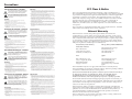
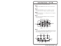
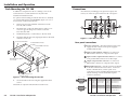
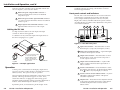
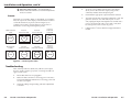
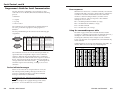
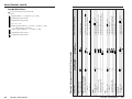
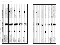
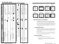
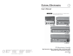
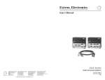
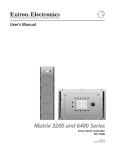
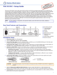
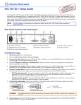
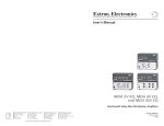
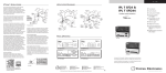
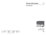
User’s Manual
TSC 100
www.extron.com
Extron Electronics, USA
Extron Electronics, Europe
Extron Electronics, Asia
Extron Electronics, Japan
1230 South Lewis Street
Anaheim, CA 92805
USA
714.491.1500
Fax 714.491.1517
Beeldschermweg 6C
3821 AH Amersfoort
The Netherlands
+31.33.453.4040
Fax +31.33.453.4050
135 Joo Seng Road, #04-01
PM Industrial Building
Singapore 368363
+65.6383.4400
Fax +65.6383.4664
Daisan DMJ Building 6F
3-9-1 Kudan Minami
Chiyoda-ku, Tokyo 102-0074 Japan
+81.3.3511.7655
Fax +81.3.3511.7656
© 2004 Extron Electronics. All rights reserved.
Transcoding Standards Converter
68-623-01
Rev. C
12 04
Precautions
Safety Instructions • English
This symbol is intended to alert the user of important
operating and maintenance (servicing) instructions
in the literature provided with the equipment.
This symbol is intended to alert the user of the
presence of uninsulated dangerous voltage within
the product's enclosure that may present a risk of
electric shock.
Caution
Read Instructions • Read and understand all safety and operating
instructions before using the equipment.
Retain Instructions • The safety instructions should be kept for future
reference.
Follow Warnings • Follow all warnings and instructions marked on the
equipment or in the user information.
Avoid Attachments • Do not use tools or attachments that are not
recommended by the equipment manufacturer because they may be
hazardous.
Consignes de Sécurité • Français
Ce symbole sert à avertir l’utilisateur que la
documentation fournie avec le matériel contient des
instructions importantes concernant l’exploitation
et la maintenance (réparation).
Ce symbole sert à avertir l’utilisateur de la présence
dans le boîtier de l’appareil de tensions dangereuses
non isolées posant des risques d’électrocution.
Attention
Lire les instructions• Prendre connaissance de toutes les consignes de
sécurité et d’exploitation avant d’utiliser le matériel.
Conserver les instructions• Ranger les consignes de sécurité afin de
pouvoir les consulter à l’avenir.
Respecter les avertissements • Observer tous les avertissements et
consignes marqués sur le matériel ou présentés dans la documentation
utilisateur.
Eviter les pièces de fixation • Ne pas utiliser de pièces de fixation ni
d’outils non recommandés par le fabricant du matériel car cela
risquerait de poser certains dangers.
Sicherheitsanleitungen • Deutsch
Dieses Symbol soll dem Benutzer in der im
Lieferumfang enthaltenen Dokumentation
besonders wichtige Hinweise zur Bedienung und
Wartung (Instandhaltung) geben.
Dieses Symbol soll den Benutzer darauf aufmerksam
machen, daß im Inneren des Gehäuses dieses
Produktes gefährliche Spannungen, die nicht isoliert
sind und die einen elektrischen Schock verursachen
können, herrschen.
Achtung
Lesen der Anleitungen • Bevor Sie das Gerät zum ersten Mal verwenden,
sollten Sie alle Sicherheits-und Bedienungsanleitungen genau
durchlesen und verstehen.
Aufbewahren der Anleitungen • Die Hinweise zur elektrischen Sicherheit
des Produktes sollten Sie aufbewahren, damit Sie im Bedarfsfall darauf
zurückgreifen können.
Befolgen der Warnhinweise • Befolgen Sie alle Warnhinweise und
Anleitungen auf dem Gerät oder in der Benutzerdokumentation.
Keine Zusatzgeräte • Verwenden Sie keine Werkzeuge oder Zusatzgeräte,
die nicht ausdrücklich vom Hersteller empfohlen wurden, da diese eine
Gefahrenquelle darstellen können.
Instrucciones de seguridad • Español
Este símbolo se utiliza para advertir al usuario sobre
instrucciones importantes de operación y
mantenimiento (o cambio de partes) que se desean
destacar en el contenido de la documentación
suministrada con los equipos.
Este símbolo se utiliza para advertir al usuario sobre
la presencia de elementos con voltaje peligroso sin
protección aislante, que puedan encontrarse dentro
de la caja o alojamiento del producto, y que puedan
representar riesgo de electrocución.
Precaucion
Leer las instrucciones • Leer y analizar todas las instrucciones de
operación y seguridad, antes de usar el equipo.
Conservar las instrucciones • Conservar las instrucciones de seguridad
para futura consulta.
Obedecer las advertencias • Todas las advertencias e instrucciones
marcadas en el equipo o en la documentación del usuario, deben ser
obedecidas.
Evitar el uso de accesorios • No usar herramientas o accesorios que no
sean especificamente recomendados por el fabricante, ya que podrian
implicar riesgos.
FCC Class A Notice
Warning
Power sources • This equipment should be operated only from the power source
indicated on the product. This equipment is intended to be used with a main
power system with a grounded (neutral) conductor. The third (grounding) pin is
a safety feature, do not attempt to bypass or disable it.
Power disconnection • To remove power from the equipment safely, remove all
power cords from the rear of the equipment, or the desktop power module (if
detachable), or from the power source receptacle (wall plug).
Power cord protection • Power cords should be routed so that they are not likely to
be stepped on or pinched by items placed upon or against them.
Servicing • Refer all servicing to qualified service personnel. There are no userserviceable parts inside. To prevent the risk of shock, do not attempt to service
this equipment yourself because opening or removing covers may expose you to
dangerous voltage or other hazards.
Slots and openings • If the equipment has slots or holes in the enclosure, these are
provided to prevent overheating of sensitive components inside. These openings
must never be blocked by other objects.
Lithium battery • There is a danger of explosion if battery is incorrectly replaced.
Replace it only with the same or equivalent type recommended by the
manufacturer. Dispose of used batteries according to the manufacturer's
instructions.
Note: This equipment has been tested and found to comply with the limits for a
Class A digital device, pursuant to part 15 of the FCC Rules. These limits are designed
to provide reasonable protection against harmful interference when the equipment is
operated in a commercial environment. This equipment generates, uses and can
radiate radio frequency energy and, if not installed and used in accordance with the
instruction manual, may cause harmful interference to radio communications.
Operation of this equipment in a residential area is likely to cause harmful
interference, in which case the user will be required to correct the interference at his
own expense.
Note: This unit was tested with shielded cables on the peripheral devices. Shielded
cables must be used with the unit to ensure compliance.
Avertissement
Alimentations• Ne faire fonctionner ce matériel qu’avec la source d’alimentation
indiquée sur l’appareil. Ce matériel doit être utilisé avec une alimentation
principale comportant un fil de terre (neutre). Le troisième contact (de mise à la
terre) constitue un dispositif de sécurité : n’essayez pas de la contourner ni de la
désactiver.
Déconnexion de l’alimentation• Pour mettre le matériel hors tension sans danger,
déconnectez tous les cordons d’alimentation de l’arrière de l’appareil ou du
module d’alimentation de bureau (s’il est amovible) ou encore de la prise secteur.
Protection du cordon d’alimentation • Acheminer les cordons d’alimentation de
manière à ce que personne ne risque de marcher dessus et à ce qu’ils ne soient pas
écrasés ou pincés par des objets.
Réparation-maintenance • Faire exécuter toutes les interventions de réparationmaintenance par un technicien qualifié. Aucun des éléments internes ne peut être
réparé par l’utilisateur. Afin d’éviter tout danger d’électrocution, l’utilisateur ne
doit pas essayer de procéder lui-même à ces opérations car l’ouverture ou le
retrait des couvercles risquent de l’exposer à de hautes tensions et autres dangers.
Fentes et orifices • Si le boîtier de l’appareil comporte des fentes ou des orifices,
ceux-ci servent à empêcher les composants internes sensibles de surchauffer. Ces
ouvertures ne doivent jamais être bloquées par des objets.
Lithium Batterie • Il a danger d'explosion s'll y a remplacment incorrect de la
batterie. Remplacer uniquement avec une batterie du meme type ou d'un ype
equivalent recommande par le constructeur. Mettre au reut les batteries usagees
conformement aux instructions du fabricant.
Vorsicht
Stromquellen • Dieses Gerät sollte nur über die auf dem Produkt angegebene
Stromquelle betrieben werden. Dieses Gerät wurde für eine Verwendung mit
einer Hauptstromleitung mit einem geerdeten (neutralen) Leiter konzipiert. Der
dritte Kontakt ist für einen Erdanschluß, und stellt eine Sicherheitsfunktion dar.
Diese sollte nicht umgangen oder außer Betrieb gesetzt werden.
Stromunterbrechung • Um das Gerät auf sichere Weise vom Netz zu trennen,
sollten Sie alle Netzkabel aus der Rückseite des Gerätes, aus der externen
Stomversorgung (falls dies möglich ist) oder aus der Wandsteckdose ziehen.
Schutz des Netzkabels • Netzkabel sollten stets so verlegt werden, daß sie nicht
im Weg liegen und niemand darauf treten kann oder Objekte darauf- oder
unmittelbar dagegengestellt werden können.
Wartung • Alle Wartungsmaßnahmen sollten nur von qualifiziertem
Servicepersonal durchgeführt werden. Die internen Komponenten des Gerätes
sind wartungsfrei. Zur Vermeidung eines elektrischen Schocks versuchen Sie in
keinem Fall, dieses Gerät selbst öffnen, da beim Entfernen der Abdeckungen die
Gefahr eines elektrischen Schlags und/oder andere Gefahren bestehen.
Schlitze und Öffnungen • Wenn das Gerät Schlitze oder Löcher im Gehäuse
aufweist, dienen diese zur Vermeidung einer Überhitzung der empfindlichen
Teile im Inneren. Diese Öffnungen dürfen niemals von anderen Objekten
blockiert werden.
Litium-Batterie • Explosionsgefahr, falls die Batterie nicht richtig ersetzt wird.
Ersetzen Sie verbrauchte Batterien nur durch den gleichen oder einen
vergleichbaren Batterietyp, der auch vom Hersteller empfohlen wird. Entsorgen
Sie verbrauchte Batterien bitte gemäß den Herstelleranweisungen.
Advertencia
Alimentación eléctrica • Este equipo debe conectarse únicamente a la fuente/tipo
de alimentación eléctrica indicada en el mismo. La alimentación eléctrica de este
equipo debe provenir de un sistema de distribución general con conductor
neutro a tierra. La tercera pata (puesta a tierra) es una medida de seguridad, no
puentearia ni eliminaria.
Desconexión de alimentación eléctrica • Para desconectar con seguridad la
acometida de alimentación eléctrica al equipo, desenchufar todos los cables de
alimentación en el panel trasero del equipo, o desenchufar el módulo de
alimentación (si fuera independiente), o desenchufar el cable del receptáculo de
la pared.
Protección del cables de alimentación • Los cables de alimentación eléctrica se
deben instalar en lugares donde no sean pisados ni apretados por objetos que se
puedan apoyar sobre ellos.
Reparaciones/mantenimiento • Solicitar siempre los servicios técnicos de personal
calificado. En el interior no hay partes a las que el usuario deba acceder. Para
evitar riesgo de electrocución, no intentar personalmente la reparación/
mantenimiento de este equipo, ya que al abrir o extraer las tapas puede quedar
expuesto a voltajes peligrosos u otros riesgos.
Ranuras y aberturas • Si el equipo posee ranuras o orificios en su caja/alojamiento,
es para evitar el sobrecalientamiento de componentes internos sensibles. Estas
aberturas nunca se deben obstruir con otros objetos.
Batería de litio • Existe riesgo de explosión si esta batería se coloca en la posición
incorrecta. Cambiar esta batería únicamente con el mismo tipo (o su equivalente)
recomendado por el fabricante. Desachar las baterías usadas siguiendo las
instrucciones del fabricante.
Extron’s Warranty
Extron Electronics warrants this product against defects in materials and
workmanship for a period of three years from the date of purchase. In the event of
malfunction during the warranty period attributable directly to faulty workmanship
and/or materials, Extron Electronics will, at its option, repair or replace said products
or components, to whatever extent it shall deem necessary to restore said product to
proper operating condition, provided that it is returned within the warranty period,
with proof of purchase and description of malfunction to:
USA, Canada, South America,
and Central America:
Europe, Africa, and the Middle East:
Extron Electronics
1230 South Lewis Street
Anaheim, CA 92805, USA
Extron Electronics, Europe
Beeldschermweg 6C
3821 AH Amersfoort
The Netherlands
Asia:
Japan:
Extron Electronics, Asia
135 Joo Seng Road, #04-01
PM Industrial Bldg.
Singapore 368363
Extron Electronics, Japan
Daisan DMJ Bldg. 6F,
3-9-1 Kudan Minami
Chiyoda-ku, Tokyo 102-0074
Japan
This Limited Warranty does not apply if the fault has been caused by misuse,
improper handling care, electrical or mechanical abuse, abnormal operating conditions
or non-Extron authorized modification to the product.
If it has been determined that the product is defective, please call Extron and ask for
an Applications Engineer at (714) 491-1500 (USA), 31.33.453.4040 (Europe),
65.6383.4400 (Asia), or 81.3.3511.7655 (Japan) to receive an RA# (Return
Authorization number). This will begin the repair process as quickly as possible.
Units must be returned insured, with shipping charges prepaid. If not insured, you
assume the risk of loss or damage during shipment. Returned units must include the
serial number and a description of the problem, as well as the name of the person to
contact in case there are any questions.
Extron Electronics makes no further warranties either expressed or implied with
respect to the product and its quality, performance, merchantability, or fitness for any
particular use. In no event will Extron Electronics be liable for direct, indirect, or
consequential damages resulting from any defect in this product even if Extron
Electronics has been advised of such damage.
Please note that laws vary from state to state and country to country, and that some
provisions of this warranty may not apply to you.
Quick Start Guide — TSC 100
To install and set up the TSC 100, follow these steps:
Step 1
Turn all of the equipment off and disconnect it from the power
source.
Step 2
Rack mount the TSC 100, or place it on a desktop. See “Rack
Mounting the TSC 100” in chapter 2, Installation and Operation.
Step 3
Attach the input cable(s). See “Cabling the TSC 100” in chapter 2,
Installation and Operation.
Step 4
Attach output and loopout cables, then attach an RS-232/422
controller (if desired).
Composite S-Video Composite
Video Input Input Video Output
COMPOSITE
1
2
O
U
T
P
U
T
S
I
N
P
U
T
S
POWER
9V
1A MAX
Power
Connection
COMPOSITE
RS-232/422
Connector
S-VIDEO
S-VIDEO
Composite S-Video
Video
Loopout
Loopout
RS-232/422
S-Video
Output
Step 5
Connect power cords and turn on the equipment in the following
order: output devices (projectors, monitors, etc.), RS-232 controller,
TSC 100, and input devices (DSS, cable boxes, etc.).
Output Picture Control
Select
Select
INPUT
Input
Select
PICTURE
CONTROLS
OUTPUT
Adjust
Knob
ADJUST
COLOR
TINT
1
NTSC
BRIGHT
2
PAL
CONTRAST
MIN/
MAX
TSC 100
TRANSCODING STANDARDS CONVERTER
Min/Max
Indicator
LED
Input Output Type Picture Control
LEDs
LEDs
LEDs
TSC 100 • Quick Start Guide
QS-1
Quick Start Guide — TSC 100, cont’d
Table of Contents
Chapter 1 • Introduction .......................................................... 1-1
Step 6
Select an input and an output standard using the front panel
buttons or the RS-232 controller.
Step 7
The picture should now appear. If not, ensure that all devices are
plugged in and receiving power. Check the cabling and make
adjustments as needed. Select a different input to check for a display.
About the TSC 100 ................................................................. 1-2
Features ...................................................................................... 1-2
Chapter 2 • Installation and Operation ........................ 2-1
Rack Mounting the TSC 100 .............................................. 2-2
Connections .............................................................................. 2-3
Rear panel connections ......................................................... 2-3
Cabling the TSC 100 ............................................................... 2-4
Optimizing the Video
Step 1
Operation ................................................................................... 2-4
Complete the basic setup (described above) and obtain a picture on
the output display.
Front panel controls and indicators ..................................... 2-5
Presets .................................................................................... 2-6
Troubleshooting ..................................................................... 2-6
Step 2
Select Aspect Ratio Preset or size and center the image through the
control program (see to page 2-6), if needed.
Chapter 3 • Serial Control ....................................................... 3-1
Programmer’s Guide for Serial Communication ... 3-2
Step 3
Adjust top and bottom blanking, if needed, to remove edge noise.
Step 4
Using the Picture Controls button, select Brightness, then adjust the
level using the Adjust knob.
Step 5
Using the Picture Controls button, select Contrast, then adjust the
contrast using the Adjust knob.
Step 6
Using the Picture Controls button, select Color, then adjust the color
using the Adjust knob.
Step 7
Using the Picture Controls button, select Tint, then adjust the tint
using the Adjust knob (see example illustration below).
B. Adjust using knob.
INPUT
PICTURE
CONTROLS
OUTPUT
ADJUST
TINT
NTSC
BRIGHT
2
PAL
CONTRAST
Control Software for Windows® .................................... 3-9
Installing the software .......................................................... 3-9
Using the software ................................................................ 3-9
Using the help system ......................................................... 3-10
Appendix A • Specifications, Part Numbers,
and Accessories ............................................................................. A-1
Specifications ......................................................................... A-2
Parts ............................................................................................. A-4
Included Parts ....................................................................... A-4
Accessories ............................................................................ A-4
Cables .................................................................................... A-4
Adapters ................................................................................ A-4
COLOR
1
Device-initiated messages ..................................................... 3-2
Error responses ...................................................................... 3-2
Using the command/response table ..................................... 3-3
Symbol definitions ................................................................. 3-3
Command/response table for SIS commands ....................... 3-5
Command/response table for Special Function SIS commands
................................................................................................ 3-9
MIN/
MAX
TSC 100
All trademarks mentioned in this manual are the properties of their respective owners.
TRANSCODING STANDARDS CONVERTER
68-623-01
Rev. C
12 04
A. Press to select tint.
QS-2
TSC 100 • Quick Start Guide
TSC 100 • Table of Contents
i
Table of Contents, cont’d
TSC 100
1
Chapter One
Introduction
About the TSC 100
Features
ii
TSC 100 • Table of Contents
Introduction
About the TSC 100
The Extron TSC 100 is a transcoder and standards converter that
allows worldwide compatibility with video standards such as
NTSC 3.58, NTSC 4.43, SECAM, and PAL. As a transcoder, it is
able to take one video format, such as an analog composite
signal, and transcode it into another video format, such as an
S-video signal. It provides picture adjustment capability as well
as RS-232/RS-422 control.
Inputs, output standard (NTSC or PAL), and picture controls are
selectable from the front panel. RS-232/RS-422 communication
is available for several advanced features, including
autoswitching, top and bottom blanking, and several sizing
options.
The TSC 100 ships with an external, desktop, 9 VDC power
supply, which accepts 100-240VAC input.
Features
Autoswitching ability — The TSC 100 can be set to detect an
active S-video signal and automatically switch to S-video
when active (RS-232/RS-422 activated).
Factory aspect ratio presets — Three predetermined sizing and
centering settings for PAL and NTSC output are stored in
the TSC 100 and are selectable through RS-232 or RS-422.
Picture controls — Color, tint, contrast, and brightness can be
adjusted through the front panel, and sizing and
centering through RS-232 or RS-422.
Choice of black screen or color bars with no input signal —
The TSC 100 will output either a black screen or Color
Bars, whichever the user prefers, when no input signal is
detected (RS-232/RS-422 activated).
Encoder/decoder — Encodes an S-video input signal (on a 4-pin
mini DIN connector) to composite video output (on a
BNC connector) and decodes composite input signal (on a
BNC connector) to an S-video output (on a 4-pin mini
DIN connector).
Executive Mode — The TSC 100 can be set to executive mode,
which locks the front panel and prevents unauthorized
changes to important settings.
Standards converter — The TSC converts a PAL video input
signal to an NTSC video output and converts an NTSC
video input signal to a PAL video output.
Variable top and bottom blanking — The TSC 100 allows the
user to eliminate edge noise caused by tape head
switching and captioning.
1-2
TSC 100 • Introduction
TSC 100
2
Chapter Two
Installation and Operation
Rack Mounting the TSC 100
Connections
Operation
Troubleshooting
Installation and Operation
Rack Mounting the TSC 100
Connections
In addition to using the TSC 100 on a desktop, it can also be
rack mounted. To rack mount the TSC 100, follow the
installation instructions below.
All connections, including power, input and output, and
control, are on the rear panel of the TSC 100. See figure 2.
2
For optional rack mounting, mount the TSC 100 on a standard,
19" 1U Rack Shelf (Extron part #60-190-01) (figure 1) in one of
four locations on the front of the rack.
1.
If feet were previously installed on the bottom of the
TSC 100, remove them.
2.
Mount the TSC on the rack shelf using two 4-40 x 3/16”
screws in opposite (diagonal) corners to secure the
TSC 100 to the shelf.
3.
Install blank panel(s) or other unit(s) to the rack shelf.
4.
Insert the shelf into the rack, aligning the holes in the shelf
with those of the rack.
1U Universal Rack Shelf
1/2 Rack Width Front False
Faceplate
9V
1A MAX
1
(2) 4-40 x 3/16"
Screws
OU
TP
UT
1
2
NT
SC
PA
L
PI
CO CTUR
NT E
RO
LS
CO
LO
AD
TIN R
JU
T
ST
BR
IGH
CO T
NT
RA
ST
TRA
NS
CO
MI
DIN
G STA
ND
AR
TS
DS
C
CO
N/
MA
10 X
0
NV
ER
TER
Use 2 mounting holes on
opposite corners.
Figure 1 — Rack mounting the TSC 100
5.
5
Secure the shelf to the rack using the supplied machine
screws.
This shelf can only be mounted in the front of the rack.
1
9
6
Female
1
5
6
9
Male
2-2
TSC 100 • Installation and Operation
O
U
T
P
U
T
S
5
COMPOSITE
S-VIDEO
S-VIDEO
6
7
8
RS-232/422
Rear panel connections
Both front false faceplates
use 2 screws.
T
2
I
N
P
U
T
S
Figure 2 — TSC 100 rear panel
1/4 Rack Width Front False
Faceplate
INPU
COMPOSITE
1
POWER
4
3
1
Power connection — Plug the external 9 VDC power
supply into this connector. The power supply is
included with the unit.
2
Input 1 composite BNC connector — Connect one
BNC female connector for composite video input.
3
Input 2 S-video 4-pin mini DIN connector — Connect
one 4-pin mini DIN connector for S-video input.
4
Output composite BNC connector — Connect one
BNC female connector for composite video output.
5
RS-232/422 connector — Use this connector for RS-232
or RS-422 communications and control. Connect an
RS-232 or RS-422 device (control system or PC
computer) for remote switching between inputs and
remote centering control to this female 9-pin D
connector (see below).
Pin
RS-232
Description
RS-422
1
2
3
4
5
6
7
8
9
—
Tx
Rx
—
Transmit data
Receive data
—
TxRx-
—
Transmit data (-)
Receive data (-)
—
Gnd
—
—
—
—
—
Signal ground
—
—
—
—
—
Gnd
—
Rx+
Tx+
—
—
Signal ground
Description
—
Receive data (+)
Transmit data (+)
—
TSC 100 • Installation and Operation
2-3
Installation and Operation, cont’d
Software for RS-232 or RS-422 control is included with the TSC
100. See chapter 3, Serial Control for details.
6
Buffered loopout composite BNC connector —
Connect one BNC female connector for buffered
composite loopout.
7
Buffered loopout S-video 4-pin mini-DIN connector
— Connect one 4-pin mini DIN connector for buffered
S-video loopout.
8
Output 4-pin S-video mini DIN connector — One
4-pin mini DIN connector for S-video output.
troubleshooting tips do not help, call the Extron S3 Sales &
Technical Support Hotline.
Front panel controls and indicators
The TSC 100’s controls and indicators are located on the front
panel (figure 4). Push buttons are used to select the input
source, output standard, and picture controls (Color, Tint,
Bright, and Contrast), and LEDs indicate the options selected.
An Adjust knob is provided to make adjustments to the picture
control element selected.
2
3
4
5
7
6
Cabling the TSC 100
Use high resolution cable for all video input and output
connections. Refer to the Appendix.
To cable the TSC 100, connect the input and output devices to
the device using figure 3 as a guide.
INPUT
PICTURE
CONTROLS
OUTPUT
ADJUST
COLOR
TINT
1
1
NTSC
BRIGHT
2
PAL
CONTRAST
MIN/
MAX
8
TSC 100
TRANSCODING STANDARDS CONVERTER
Figure 4 — TSC 100 front panel
ITE
OS
MP
CO
O
U
T
P
U
T
S
2
1
PAL VCR
Buffered
Loop-Out
R
WE
PO
12V X
MA
1A
I
N
P
U
T
S
2/4
22
Extron
TSC 100
-23
RS
NTSC VCR
O
IDE
S-V
1
Input selector button — Press this button to select
between input 1 (composite) and input 2 (S-video).
2
Input selection indicator LEDs — A green LED lights
to indicate which input is selected.
3
Output selector button — Press this button to select
between NTSC or PAL output on the composite or
S-video output connectors.
4
Output selection indicator LEDs — A yellow LED
lights to indicate which standard output (NTSC or
PAL) is selected.
5
Picture Controls button — Press this button to select
the element of the picture to be adjusted by the Adjust
knob 7 (either Color, Tint, Bright, or Contrast).
6
Picture Controls selection indicator LEDs — A yellow
LED lights to indicate the element of the picture
selected for adjustment.
7
Adjust knob — Rotate this knob to adjust the element
of the picture selected by the Picture Controls button
and indicated by the Picture Controls selection
indicator LED.
O
IDE
S-V
ITE
OS
MP
CO
User selects between S-video
or composite inputs and
between NTSC and PAL
outputs; selectable from
the front panel. Composite
input is shown.
NTSC Monitor
Figure 3 — Example application
Operation
Connect power cords and turn on the display output devices
(projectors, monitors, VCRs), interface, and input devices (DSS,
cable box, DVD). The system is ready for operation.
Select an input from the front panel button or the remote control
(RS-232). The image should now appear on screen. If not,
ensure that all devices are plugged in and receiving power.
Check the cabling and button settings, and make adjustments as
needed. Select a different input to check for a picture.
If problems persist, see Troubleshooting in this chapter. If the
2-4
TSC 100 • Installation and Operation
TSC 100 • Installation and Operation
2-5
Installation and Operation, cont’d
8
Min / Max indicator LED — A red LED lights to
indicate when the minimum or maximum adjustment
levels are reached.
Presets
When PAL is converted to NTSC or when NTSC is converted to
PAL, the aspect ratio of the display can be distorted. In order to
correct this distortion, six presets (shown in figure 5) are
available. Please refer to chapter three, RS-232 Control, for
information on choosing and using these presets.
NTSC Converted
to PAL
Preset #1
Center Horizontally
Preset #2
Scale Up Vertically
Preset #3
Scale Down
Horizontally
PAL
PAL
PAL
Preset #1
Center Horizontally
Preset #2
Scale Down Vertically
Preset #3
Scale Up
Horizontally
NTSC
NTSC
NTSC
PAL Converted
to NTSC
PAL
NTSC
4.
To ensure correct cabling from the TSC to the display
device, turn on the Color Bars output, using an SIS
command, and disconnect the input signal.
5.
Check that the appropriate output standard is selected.
6.
To test the system setup and output, substitute a video test
generator (VTG) for one of the video inputs. To use a
VTG, unplug the input and output devices and the TSC’s
power cord, replace the video source with a VTG, then
reconnect power cord to restore AC power.
7.
Call the Extron S3 Sales & Technical Support Hotline if
needed.
Figure 5 — Preset aspect ratios
Troubleshooting
Turn on the input devices (DVD, DSS, cable box) and output
device(s) (VCRs, monitors, projectors). The image should now
appear on the screen.
2-6
1.
Ensure that all devices are plugged in.
2.
Make sure that each device is receiving power. The TSC’s
front panel LEDs light if the device is receiving power and
an active sync signal.
3.
Check the cabling and grounding, and make adjustments
as needed.
TSC 100 • Installation and Operation
TSC 100 • Installation and Operation
2-7
Installation and Operation, cont’d
TSC 100
3
Chapter Three
Serial Control
Programmer’s Guide for Serial Communication
Control Software for Windows®
2-8
TSC 100 • Installation and Operation
Serial Control, cont’d
Programmer’s Guide for Serial Communication
The TSC 100 can be controlled by a host computer or other
control device via an RS-232/422 connection with the following
protocol:
• 9600 baud
• 1 stop bit
• no parity
• no flow control
The control device can use either Extron’s Simple Instruction
Set™ (SIS™) or the Extron graphical control program for
Windows®.
The rear panel RS-232 9-pin D connector has the following pin
assignments:
5
1
9
6
Female
1
5
6
9
Male
Pin
RS-232
Description
RS-422
1
2
3
4
5
6
7
8
9
—
Tx
Rx
—
Transmit data
Receive data
—
TxRx-
—
Transmit data (-)
Receive data (-)
—
Gnd
—
—
—
—
—
Signal ground
—
—
—
—
—
Gnd
—
Rx+
Tx+
—
—
Signal ground
Description
—
Receive data (+)
Transmit data (+)
—
Error responses
When the TSC 100 receives a valid SIS command, it executes the
command and sends a response to the host device. If the device
is unable to execute the command because the command is
invalid or contains invalid parameters, it returns an error
response to the host. The error response codes and their
descriptions are as follows:
E01 — Invalid input channel number (too large)
E09 — Invalid function number (too large)
E10 — Invalid command
E13 — Invalid value (out of range)
Using the command/response table
The table on page 3-4 lists the commands that the switcher
recognizes as valid, the responses that are returned to the host, a
description of the command’s function or the results of
executing the command, and an example of each command.
Lower case characters are acceptable in the command field only
where indicated.
Symbol definitions are shown at the beginning of the table. An
ASCII to HEX conversion table is provided in figure 6.
ASCII to HEX Conversion Table
•
SIS commands consist of one or more characters per field. No
special characters are required to begin or end a command
sequence. When the TSC 100 determines that a command is
valid, it executes the command and sends a response to the host
device. All responses from the TSC 100 to the host end with a
carriage return and a line feed (CR/LF = ), which signals the
end of the response character string. A string is one or more
characters.
Device-initiated messages
Figure 6 — ASCII-to-HEX conversion table
When a local event such as an input selection occurs, the
TSC 100 responds by sending a message to the host. No
response is required from the host. The device-initiated
message is shown below (underlined).
(C)COPYRIGHT 2002, EXTRON ELECTRONICS TSC 100,
Vx.xx
The device displays the copyright message when it first
powers on. Vx.xx is the firmware version number.
3-2
TSC 100 • Serial Control
TSC 100 • Serial Control
3-3
3-4
TSC 100 • Serial Control
TSC 100 • Serial Control
Specific value
Example:
Contrast
Specific value
Example:
Increment tint value
Decrement tint value
View tint value
Tint
Specific value
Example:
Increment color value
Decrement color value
View color value
=
^
29 ^
X7
X2 T
29T
+T
-T
T
29C
+C
-C
C
X7 C
=
View video type
Color
1=
X6
X1 !
Set video output standard
Example:
Video output standard
Select input source
X6
X1
Con X7
Con 29
X2
Tin X2
Tin 29
Tin X2
Tin X2
X7
Col X7
Col 29
Col X7
Col X7
X6
Rte
1
Chn
X8 = Adjustment range (0-210)
Input selection
X7 = Adjustment range (0-127)
X6
X6 .
Selects contrast value X7 (0-127).
Selects contrast value of 29.
Select tint value X2 (0-255).
Select tint value of 29.
Select the next higher tint value.
Select the next lower tint value.
View the tint value.
Select color value X7 (0-127).
Select color value of 29.
Select the next higher color value.
Select the next lower color value.
View the current color value setting.
Output video type is
Set the video output standard to
Video output type is 1 (NTSC).
Set the input source.
Additional description
3 = NTSC 4.43, 4 = SECAM
X6 = Video output standard — 1 = NTSC, 2 = PAL
Response
X5 = Video input Standard — 0 = None, 1 = NTSC, 2 = PAL,
(TSC 100 to host)
X4 = 0 = on, 1 = off
(host to TSC 100)
X3 = Adjustment range (0-100)
ASCII Command
= CR/LF (carriage return/line feed)
• = Space
X1 = Input number (1 = composite, 2 = S-video)
X2 = Adjustment range (0-255)
Command
Command/response table for SIS commands
Serial Control, cont’d
Symbol definitions
3-5
3-6
^
View contrast value
TSC 100 • Serial Control
View top value
+)
-)
)
Increase top value
Decrease top value
View top value
Specific value
X3
-(
(
Decrease top value
Bottom blanking
+(
X3
1X
0X
X
+;
-;
;
X8
)
(
;
TSC 100 • Serial Control
Blb
Blb
Blb
Blb
Blt
Blt
Blt
Blt
X4
X8
X8
X8
X8
X3
X3
X3
X3
View the number of lines blanked at bottom.
Decrease the number of bottom lines blanked.
Increase the number of bottom lines blanked.
Set number of lines to blank at the bottom of the
picture.
View the number of lines blanked at top.
Decrease the number of top lines blanked.
X3
Increase the number of top lines blanked.
X3
Set the number of lines to blank at the top of the
picture.
Lock the front panel. RS-232 adjustments only.
Unlock the front panel.
Show the executive mode status.
Set the vertical size to X8 (0-210).
Make the picture taller.
Make the picture shorter.
View the vertical size setting.
Additional description
Sets horizontal size to X2 (0-255).
Widen the picture.
Make the picture narrower.
View the horizontal size value.
Sets vertical centering to X2 (0-255).
Shift right.
Shift left.
View the vertical centering value.
Sets horizontal centering to X2 (0-255).
Shift right.
Shift left.
View the horizontal centering value.
Select brightness value X2 (0-255).
Select the next higher brightness value.
Select the next lower brightness value.
View the current brightness value setting.
View the current contrast value setting.
Select the next lower contrast value.
Select the next higher contrast value.
Additional description
X3
X3
Exe1
Exe0
Vsz
Vsz
Vsz
Vsz
Response
(TSC 100 to host)
(host to TSC 100)
X2
X2
X2
X2
X2
X2
X2
X2
X2
X2
X2
X2
X2
X2
X2
Vph
Vph
Vph
Vph
Hsz
Hsz
Hsz
Hsz
X7
X7
X7
X2
Hph
Hph
Hph
Hph
Brt
Brt
Brt
Con
Con
ASCII Command
+:
-:
:
/
H
Y
X2 :
+/
-/
/
X2
+H
-H
H
X2
+Y
-Y
Y
Increase top value
Specific value
Top blanking
Enable executive
Disable executive
View status
Executive mode
Specific value
Increase size
Decrease size
View
Vertical size
Command
Specific value
Increase size
Decrease size
View
Horizontal size
Specific value
Increment
Decrement
View
Vertical shift
Specific value
Increment
Decrement
View
Horizontal shift
Specific value
Increment color value up
Decrement color value down
View color value
X2
-^
Brightness
+^
(host to TSC 100)
Increment contrast value
Response
(TSC 100 to host)
ASCII Command
Decrement contrast value
Contrast (continued)
Command
Command/response table for SIS commands (cont’d)
Serial Control, cont’d
3-7
3-8
TSC 100 • Serial Control
n/N
i/I
q/Q
J
1J
0J
Example
Aspect Ratio
Example
Color bars
Autoswitch
Example
X?
*
X!
# , where
is the function number and
X!
X!
X!
5*1#
5*
2*1#
2*
#
#
10* X4 #
10*1#
X?
X?
#
X!
X!
Asp 1
Asp
Blk 1
Blk
Aut X4
Aut 1
Enable aspect ratio #1.
x! = 1, 2, or 3 (see Figure 7).
0 = Off (black screen with no input
signal).
1 = On (Color Bars Display on output)
Enable Color Bars Display on output.
0 = Off (default), 1 = On.
Enable autoswitch mode.
X?
is the value. To
Shows the controller firmware
version.
Displays the Extron part number.
Typ X5 displays the type of input
signal that is automatically sensed by
the decoder. This cannot be changed.
Zpx
Reset everything: all settings
and adjustments revert to factory
default.
Show Color Bars test pattern.
Remove Color Bars test
pattern.
Additional description
#, where
is the function number. In the following table, the values of the
view a function’s setting, use
variable are different for each command/function. These values are given in the rightmost column.
The syntax for setting a special function is
X?
XX-XXX-XX
C X1 •Typ X5
x.xx
Esc zXXX
X4
Tst1
Tst0
Response
(TSC 100 to host)
ASCII Command
(host to TSC 100)
Command/Response Table for Special Function SIS Commands
Request part number
Request information
Information Requests:
Query software version
Reset: ZAP (reset to default settings)
View status
Test Pattern: Enable color bars
Disable color bars
Miscellaneous commands
Command
Serial Control, cont’d
NTSC Converted
to PAL
NTSC
PAL Converted
to NTSC
PAL
NTSC
1.
Preset #1
Center Horizontally
Preset #2
Scale Up Vertically
Preset #3
Scale Down
Horizontally
PAL
PAL
PAL
Preset #1
Center Horizontally
Preset #2
Scale Down Vertically
Preset #3
Scale Up
Horizontally
NTSC
NTSC
Figure 7 — Aspect Ratio Presets
Control Software for Windows
The included graphical control software for Windows offers
another way to control the TSC 100 via RS-232/422 in addition
to the Simple Instruction Set commands listed on the previous
pages. The TSC 100 uses Extron’s Signal Enhancement Products
Control Program, which is included with these interfaces. The
control software is compatible with Windows 3.1x, Windows 95/
98, and Windows NT.
Installing the software
To install the software onto the hard drive, run SETUP.EXE from
the floppy disk, and follow the instructions that appear on the
screen. The program requires approximately 2 MB (megabytes)
of hard disk space.
By default the installation creates a C:\TSC 100 directory, and it
places two icons (TSC 100 Control Pgm and TSC 100 Help) into
a group or folder named “Extron Electronics”.
Using the software
To run the control program, follow these steps:
Double-click on the TSC 100 Control Pgm icon in the
Extron Electronics group. The Comm menu will appear
on the screen.
TSC 100 • Serial Control
3-9
Serial Control, cont’d
2.
Click on the comm port that is
connected to the interface’s RS-232
port. The control software will “look
for” the interface at that port and read
its configuration.
The control program window (shown
below) will appear and display
current settings.
TSC 100
A
Appendix A
Figure 8 — Control program window
Using the help system
For information on program features, press
the F1 computer key or click on the Help
menu from within the control program, or
double-click on the TSC 100 Help icon in the
Extron Electronics group or folder.
Specifications, Part Numbers,
and Accessories
Specifications
Parts
3-10
TSC 100 • Serial Control
Specifications, Part Numbers, and Accessories
Specifications
DC offset ....................................... ±5 mV maximum
Sync
Video
Gain ...............................................
Bandwidth ....................................
Differential phase error ..............
Differential gain error .................
Crosstalk .......................................
Unity
10 MHz (-3 dB)
0.3º at 3.58 MHz and 4.43 MHz
0.36% at 3.58 MHz and 4.43 MHz
-60 dB @ 3.58 MHz
Video input
Number/signal type ................... 1 NTSC/PAL S-video
1 NTSC/PAL composite video
Connectors .................................... 2 female 4-pin mini DIN (1 input, 1
buffered loop out)
2 female BNC (1 input, 1 buffered
loop out)
Nominal level ............................... 1 Vp-p for Y of S-video and for composite
video
0.3 Vp-p for C of S-video
Minimum/maximum level(s) .... S-video ....... luma: 2 Vp-p
chroma: 0.6 Vp-p
Composite video: 2 Vp-p with no offset
Impedance .................................... 75 ohms
Return loss .................................... <-13 dB @ 5 MHz
DC offset (max. allowable) ......... 1.5 V
Video processing
Decoder .........................................
Encoder .........................................
Digital sampling ..........................
Colors ............................................
9 bit digital
10 bit digital
24 bit, 8 bits per color
16.78 million
Video output
Number/signal type ................... 1 S-video and composite video
Connectors .................................... 1 female 4-pin mini DIN
1 female BNC
Nominal level ............................... 1 Vp-p for Y of S-video and for composite
video
0.3 Vp-p for C of S-video
Minimum/maximum levels ...... 0 V to 2.0 Vp-p
Impedance .................................... 75 ohms
Return loss .................................... -30 dB @ 5 MHz
A-2
TSC 100 • Specifications, Part Numbers, and Accessories
Standards
Sync input ......................... NTSC 3.58, NTSC 4.43, PAL, SECAM
Sync output ....................... NTSC 3.58, PAL
Control/remote — transcoder/converter
Serial control port ........................
Baud rate and protocol ...............
Serial control pin configurations
Program control ...........................
RS-232, 9-pin female D connector
9600 baud, 8 data bits, 1 stop bit, no parity
2 = TX, 3 = RX, 5 = GND
Extron’s control/configuration program
for Windows®
Extron’s Simple Instruction Set (SIS™)
General
External power supply ............... 100 VAC to 240 VAC, 50/60 Hz, external,
autoswitchable; to 9 VDC, 1 A, regulated
Power input requirements ......... 9 VDC, 0.20 A
Temperature/humidity .............. Storage -40° to +158°F (-40° to +70°C) /
10% to 90%, noncondensing
Operating +32° to +122°F (0° to +50°C) /
10% to 90%, noncondensing
Rack mount ................................... Yes, with optional rack shelf,
part #60-190-01
Enclosure type .............................. Metal
Enclosure dimensions ................. 1.75" H x 4.4" W x 6.5" D
(1U high, quarter rack wide)
4.4 cm H x 11.1 cm W x 16.5 cm D
(Depth excludes connectors and knobs.)
Product weight ............................. 0.8 lbs (0.4 kg)
Shipping weight .......................... 3 lbs (2 kg)
Vibration ....................................... ISTA 1A in carton (International Safe
Transit Association)
Listings .......................................... UL, CUL
Compliances ................................. CE, FCC Class A, VCCI, AS/NZS, ICES
MTBF ............................................. 30,000 hours
Warranty ....................................... 3 years parts and labor
All nominal levels are at ±10%.
Specifications are subject to change without notice.
TSC 100 • Specifications, Part Numbers, and Accessories
A-3
Specifications, Part Numbers, Accessories, cont’d
Parts
Included Parts
These items are included in each order for a TSC 100:
Included parts
Replacement part number
TSC 100
60-451-01
9 VDC, 1A external power supply
70-056-01
TSC 100 User’s Manual
Accessories
Accessories
Part number
Through-desk mounting bracket kit
70-077-02
19” 1U Universal Rack Shelf
60-190-01
Cables
Cables
Part number
S-video cable, up to 100’ (various lengths)
26-316-xx
Superflex SHR cable, BNC (various lengths)
26-383-xx
RS-232 cable, male-to-female (var. lengths)
26-433-xx
Adapters
Adapters
Part number
Male S-video to 2 female BNCs, 8”
26-353-01
Male S-video to 2 male BNCs (var. lengths)
26-353-xx
Female S-video to 2 female BNCs, 8”
26-541-01
Female S-video to 2 male BNCs (var. lengths) 26-541-xx
A-4
TSC 100 • Specifications, Part Numbers, and Accessories