1
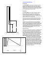
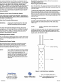
Operating Instructions Store and use these containers only in well ventilated areas. In a confined area, nitrogen gas from these units may cause suffocation by displacing air needed for breathing. Install a suitable oxygen monitor. Do not touch liquid or cold metal surfaces with your bare skin. The liquid nitrogen refrigerant is extremely cold: -196°C (-320°F). Exposure to skin or eyes to liquid, cold gas or frosted parts could result in a severe frostbitelike injury. Because of the extremely low temperature, a face shield and gloves must be worn when transferring liquid nitrogen and material into or out of these containers. Use only the necktube covers supplied with this unit or a listed replacement part. A tight fitting plug or stopper will cause a pressure increase in the container that may damage the container and/or cause personal injury. OPERATION Filling: Adding liquid nitrogen to a warm container may cause splashing and will generate a significant volume of nitrogen gas as cold liquid contacts warm refrigerator surfaces. Add liquid slowly to minimize these effects. Be sure there is adequate ventilation. Keep your head clear of the heavy volume of vapor that may be produced. It is extremely cold and could cause personal injury. WARNING: DO NOT OVERFILL. Over-filling may result in personal injury due to liquid spillage. DETERMINING LIQUID LEVEL Liquid level must be checked at regular intervals refrigeration depends on the pressure of liquid nitrogen. The liquid level in the container can be determined with a dipstick. Insert the dipstick straight into the container so that it rests on the rack positioning fixture on the bottom of the unit. After 5 to 10 seconds, withdraw the dipstick and wave it back and forth in the air. A frosted section will form representing the depth of the liquid in the container. WARNING Never use hollow rods or tubes as dipsticks. When a warm tube is inserted into liquid nitrogen, liquid will spout from the top of the tube and may cause personal injury. The liquid level chart shows volume of liquid nitrogen vs. depth for LS Series refrigerators. 0RGHO /6 /6/6/6 TW-348 /LTXLG/HYHO(TXLYD OHQWV LQ OLWHUVFP OLWHUV LQ OLWHUVFP OLWHUV INSERTING OR REMOVING RACKS To prevent unnecessary loss of liquid nitrogen and accumulation of ice, the necktube core (the stopper) should remain in the container when the stored material is not being accessed. When accessing stored material, the necktube should be removed as briefly as possible. When removing material from the racks, withdraw the rack just far enough to remove contents. Completely withdrawing the rack will unnecessarily expose the stored material to warm room temperature conditions. WARNING Some boxes have liquid drain openings, some do not. If racks are completely removed from the container, liquid nitrogen may remain in the either rack and boxes, or simply drain from the bottom. When removing racks, stop briefly at the necktube to allow liquid to drain completely, then handle the rack carefully to prevent personal injury. Avoid direct rack contact with bare skin. The use of proper personal protective gear is strongly urged cryogenic gloves, face shield and gown to protect against splashing. When room temperature is added, slowly lower the rack into the refrigerator to reduce the boiling of refrigerant and the surge of cold nitrogen gas. When inserting the rack, tilt the bottom of the rack in the direction of the index ring notch. The numbers and colors on the rack handles are a convenient aid to inventory control. SECURING CONTENTS The contents of all models may be secured with a seal or lock through tabs on the edge of the lid opposite the hinge. ROUTINE CARE AND MAINTENANCE If ice accumulates inside the necktube, a general cleaning of the refrigerator should be scheduled as soon as the stored material can LS SERIES Following are a few of the safety precautions described in the Handle with Care booklet. Please be sure to read the entire booklet. These values are approximate and are based on a standard condition with no stored material in the container. With store material, the liquid volume will be slightly less than the value of the chart. Laboratory Systems SAFETY Before using any cryogenic refrigerator, read the Handle with Care booklet provided with the unit. It details safety precautions that must be understood before using the equipment. If a replacement booklet is needed, order publication TW-10 Handle with Care from your supplier. AUTO FILL OPERATION WARNING: In order to prevent the relief device on nitrogen refrigerator(s) from opening when the system is in operation, the liquid nitrogen supply system must be protected by a pressure relief device that will open when the pressure at the inlet to the refrigerator(s) is approximately 22 psig (1.5 bar/152 kPa). Never install the supply system pressure relief device into a liquid service line. Filling the Refrigerator (Initial Fill) The LS6000-AT uses the AutoTend controller that comes preset from the factory to operate. The liquid nitrogen supply pressure at the inlet to the unit should be in the range of 10 psig (0.7 bar/69 kPa) to 20 psig (1.4 bar/138 kPa) for optimum performance. Higher operating pressures will increase transfer losses and create excessive turbulence of the liquid in the unit which can generate false signals to the liquid level controller causing the unit to underfill. In liquid phase storage applications, excessive turbulence can cause splashing which could result in personal injury and/or damage to the unit. If the liquid nitrogen supply pressure at the inlet to the unit rises above the opening pressure of the relief valve on the unit, liquid nitrogen will be discharged into surrounding area which can cause rapid and very dangerous depletion of oxygen in the atmosphere. Once this pressure relief device has opened and cooled to liquid nitrogen temperature, it will not reset until it has warmed to near ambient temperature. THIS COULD PERMIT THE ENTIRE CONTENTS OF THE LIQUID NITROGEN SUPPLY SYSTEM TO BE DISCHARGED INTO THE IMMEDIATE AREA OF THE REFRIGERATOR(S). WARNING: Maintain adequate ventilation to prevent asphyxiation hazard. (See Safety Precautions) Power Supply Connection Connect the 24 Volt AC power supply to the rear of the cryostorage system; then plug the power supply into a 110/ 120 VAC outlet. (See Figure 5 for the Electrical Supply Connections.) Turn on the AutoTend by turning the key on the front panel (see Figure 5) to the on position. The audible alarm may sound during setup; silence the alarm by pressing the button labeled MUTE. WARNING: If the fill fails to stop for any reason, quickly close the liquid supply valve to prevent overfilling until the cause of the problem can be determined. The unit is now under automatic fill control. Liquid will be added by the controller as long as the liquid supply and electrical power are maintained. Operating Parameters When materials are immersed in liquid nitrogen, they will assume the temperature of the liquid -320° F (-196° C). When material is stored in the vapor phase of the liquid, the liquid nitrogen is still a very cold refrigerant, but the units interior temperature increases somewhat as product is stored higher above the liquid. This temperature differential is not significant in many biological storage applications, and is affected by the amount of product stored in the unit, the type and size of inventory control system, and the liquid level in the unit. The liquid level in the unit is determined by the position of the sensor probes in the tube located next to the fill tube. These probes are set at installation to maintain a specific liquid level. (See Figure 4) The cycle repeats when the liquid level drops to the low level sensor over time. Sensor probes may be moved to define new high and low levels, and these levels may be set independently to vary the liquid level differential between fills. For adjusting the temperature probes see Changing Liquid Level section in this manual. Vapor Phase Storage Vapor phase storage is normally utilized when stored product is unable to withstand liquid nitrogen temperatures, or when the storage medium (vials, ampules, etc.) is not designed for liquid phase storage. In a typical vapor phase storage system, the liquid level sensors are positioned to maintain the liquid level at or below the top of the spider. This positioning allows stored product to be kept at cryogenic temperatures without being exposed to liquid nitrogen, reducing the possibility of leakage or crosscontamination. Care must be taken in the positioning of the level of refrigerant in the event of power outages, which may disable the controller for an extended period of time. Consideration must also be given to liquid nitrogen availability and delivery schedules. Liquid Phase Storage Liquid phase storage is normally utilized when liquid nitrogen temperatures are required to maintain stored product viability and the storage mediums are adequate for storage in liquid nitrogen. In a typical liquid phase storage system, the liquid level sensors are positioned to maintain the liquid level at or below the top level of the inventory control system. During operation, the upper levels of the inventory control system will at times become exposed as the liquid level fluctuates. Care must be taken to ensure that the liquid level remains below the bottom of the lid. Operating the refrigerator with high liquid levels characteristic of liquid phase storage may result in turbulence during fill cycles. Caution must be exercised if the unit lid is opened during a fill, and appropriated safety equipment should always be worn. Sensor Positioning for the AutoTend Controller The longer sensor probe (orange/yellow wires) contains the Low Level sensor in a pod. The shorter probe (red/black wires) contains the High Level sensor. The factory sensor positions will maintain a liquid level between 2.0 in. to 4.0 in. The dimensions used for the factory sensor installation are shown in Figure 2. CONTROLLER OPERATION Introduction The AUTO-TEND Control System is designed to provide simple, reliable liquid level control in your LN2 freezer. It operates on 24 Volts AC and uses a two-sensor system to open and close a solenoid valve. The liquid level, the sensor condition, the valve condition, and the LN2 supply condition are indicated by lights on the front panel. Installation: The AUTO-TEND Control System is designed to mount onto your Taylor-Wharton Cryogenic refrigerator. The components plug into the back of the control panel as follows: The Solenoid Valve has a 2-pin connector. The sensor assembly has a 4-pin connector. These plug into the mates on the back of the control panel. Stop Fill Start Fill 2.0 inches .25 inches Figure 2. Sensor Positioning for the AutoTend Figure 4. Normal Fill/Evaporation Cycle Chart The sensor assembly should be installed with the yellow and orange wires at the High Level and the black and red wires at the Low Level. These are labeled for easy reference. The Auto-Tend controller should not require additional attention to maintain liquid level if an adequate supply of liquid nitrogen is maintained. If your protocol calls for you to top off the cryostorage system at the end of a work day or work week, press the Start button. The unit will fill to the upper allowable liquid level and stop automatically. You may choose to manually stop the fill by pressing the STOP button at anytime during the fill. Normal Fill Cycle When the unit is filled and the controller is operating, the low level sensor is immersed in liquid nitrogen (see Figure 4.) Its resistance value is interpreted by the controller as in liquid. At the same time, the high level sensor is above the liquid pool sending the controller an in-gas signal. In this condition, the control panel will read Normal. As liquid nitrogen evaporates, the liquid level in the refrigerator drops slowly until the low level sensor is above the liquid and sends a different signal to the controller. The controller interprets this condition as low liquid and opens the fill solenoid valve admitting more refrigerant. The unit fills slowly, the control panel will read LOW when the liquid level is above the low level sensor. It will continue to display the green filling light until the high level sensor is immersed in liquid. Once the level of the liquid reaches the point of the high level sensor, the Solenoid Valve will close. Figure 4 illustrates this cycle in graph form where liquid level is plotted against time, and display graphics are shown as they appear at key points in the cycle. Controller Features Level LN2 Controllers The controller is designed to maintain the LN2 level in the unit within a user-defined range. The LN2 level will be maintained between the low level sensor and the high level sensor. When the liquid level reaches the low level sensor, LN2 will be added to the refrigerator until it reaches the high level sensor. Basic Operation Remote Alarm Jack: The remote alarm relay has a set of dry contacts capable of carrying 5 amperes current at 30 volts D.C. The relay is normal during any alarm condition. The remote alarm is triggered 30 minutes after an error condition occurs. The remote alarm will be reset when the error condition is corrected. Pins 1 and 2 are closed in normal operating condition while pins 2 and 3 are open in a remote alarm condition. See Figure 8. DESCRIPTION OF FRONT PANEL 1.) Automatic Fill: The control will open the solenoid valve automatically when the liquid level falls below the Low Level Sensor. It will continue filling until the High Level Sensor is covered by liquid. Manual Fill: The Start Fill button can be pressed at any time and the solenoid valve will open. If the liquid level is between High Level Sensor and the Low Level Sensor, the solenoid will stay open until the Stop Fill button is pressed or until the liquid level covers the High Level Sensor. If the liquid level is above the High Level Sensor, the solenoid valve will stay open while the user presses the Start Fill Button but will close when the user releases the button. Please Note: The maximum time that the valve will stay open when the liquid level is above the High Level sensor is one minute. The user can open the valve again by simply releasing and then pressing the Start Fill button again. Alarm Conditions: An alarm condition occurs when a sensor problem develops or the supply tank runs low on LN2. When an alarm condition does occur, the appropriate light on the front panel flashes and an audible alarm is activated. Key Lock: This turns the control On/Off. Turning the Key to the 3 oclock position provides power to the control while rotating the key 12 oclock position turns the control off. Start Fill: This button opens the solenoid valve and allows LN2 to flow into the freezer. Stop Fill & Mute: This button closes the solenoid valve and stops the flow of LN2 into the freezer. This button also silences the audible alarm. Filling LED: Lights green to indicate that the solenoid valve is open. LN2 Level LED: Lights red to indicate that the liquid level is above the high level sensor. Lights green to indicate that the liquid level is between the low level sensor and the high level sensor. Lights yellow to indicate that the liquid level is below the low level sensor. Please note: The LED will not light if the high level sensor is submerged in LN2 while the low level sensor is located in gas. The only time that this can occur is if the sensors are installed backwards. Testing the front panel lights: To test all the lights on the control except the Filling LED, press the Stop Fill & Mute button and hold for 8 seconds. Sensor Fault LED: Lights red to indicate that a sensor fault has occurred. A sensor fault can be either an open circuit or a short circuit in the sensor assembly. Testing the Remote Alarm: To test the remote alarm, press the Stop Fill & Mute button and hold for 13 seconds (5 additional seconds after testing the lights, or unplug the power supply from the wall.) Low LN2 Supply LED: Lights red to indicate that the LN2 supply is low. This is triggered when the liquid level does not reach the high level sensor within 1 hour of opening the solenoid valve. Sensor Assembly 24VAC Solenoid Valve Remote Alarm Electrical Supply Connections For LS6000 24VAC Power The liquid level in the unit is determined by the position of the sensor probes in the sensor tube next to the fill tube. These probes have been set at installation to maintain a specific liquid level. The controller operates a fill cycle that adds liquid at low level, fills to a predetermined high level, then stops the fill. The cycle repeats when liquid drops to the low level over time. Sensor probe positions may be changed to define new high and low liquid levels, and these levels may be set independently to vary the liquid level differential between fills. If a higher liquid level is desired, withdraw the sensor tube; for a low level, the sensors must be moved further into (down) the sensor tube. CAUTION: Ice or frost in the sensor tube may restrict movement of sensor probes in the tube. Do not pull excessively on sensor wiring while attempting to change sensor position. It may be necessary to remove the sensor from the container and allow it to thaw before the sensor can be repositioned. Increasing the distance between low and high sensor probes allows greater liquid level fluctuation, less frequent filling and reduced fill loses; decreasing the distance has the opposite effect. To set the liquid level to a different point, or to change the level differential, the sensors must be repositioned. Their position within the sensor tube is held in place by the sensor tube plug, which is split to allow the sensor leads to pass through. The sensor tube plug holds the sensors at the position necessary to maintain a specific liquid levels. Two different sensor heights are specified by their position within the sensor tube. The low and high sensor pods are separately positioned to set the liquid levels at which the controller will start or terminate each fill cycle. Insert the sensor leads into the perforated sensor tube to the desired height. Mark the sensor leads at the top of the sensor tube. Pull the leads out just enough to install the sensor tube plug around the marks on the sensor leads. Insert sensor plug securely into the mouth of the tube. Perform this operation carefully, so the sensor leads are not damaged. NOTE: The high level sensors must be at least 1.75 in. (5.1 cm) above the low level sensor pod. After repositioning sensors, check to be sure the sensor tube is secured to the fill tube and the sensor wires are dressed and clear of rack operation, and turn the controller on. The controller should fill the refrigerator to the new liquid level. After sensors are repositioned, the controller should maintain the liquid pool at the new operating level. Remote Alarm Connection Relay connections are provided on an external for user installation of a remote alarm circuit (see Figure 8.) Wiring external power supply and alarm devices must be supplied by the user. During an alarm condition, contacts 1 & 2 are closed and contacts 2 & 3 are open. Remote Alarm Connection on Taylor-Wharton Freezers Back panelson most Taylor-Wharton freezers are equipped with a 3 point electrical socket. The socket connects to a control board mounted, SPDT (single pole double throw) relay, rated at 10 amps, 125 VAC. 1 3 1 1 (NC) 2 2 3 (NO) 3 A Switchcraft plug (#05GM3M) connects to the above socket. It is available with leads as Taylor-Wharton part #R06K-8C20. Approximately 9 of wire extend from the plug. The gray wire connects to Pin #1, orange wire to Pin #2 and the purple wire to Pin #3. 3 1 2 To connect an AC load, such as an alarm light or buzzer, connect as shown below: AC Line ~~ Changing Liquid Level AC Line orange Alarm gray For automatic dialers and other alarm systems that are alarmed on either a contact make or break, connect as shown below: orange 2 purple Alarm on break 3 orange gray Alarm on make 2 1 MAINTENANCE LS Series CryoStorage Maintenance Defrosting your K Series CryoStorage System All liquid nitrogen storage systems are subject to ice and frost buildup over time. Regular preventive maintenance programs should be instituted to remove ice and frost from the sensor and fill tubes and from the refrigerator lid. Ice and frost build up in the sensor tube may result in false readings being relayed to the controller from the sensors. Ice can form a thermal barrier around a level sensor, rendering it insensitive to the temperature differences between vapor and liquid. Sensors and thermocouple should be removed regularly and inspected for ice and frost build up. NOTE: Ice or frost in the sensor tube may restrict the movement of sensor probes in the tube. Do not pull excessively on the sensor wiring while attempting to change sensor position. It may be necessary to remove the fill tube and tube from the container and allow it to thaw before the sensors can be repositioned.


![TSD Series -40C ULT User Manual [EN]](http://vs1.manualzilla.com/store/data/005634658_1-66c9db561a67486106446026c707a26c-150x150.png)