
1
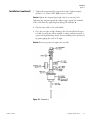
Thermo Dewars
Cryogenic Transfer Vessels
Operation Manual and Parts List
700XXXX Rev. 0
© 2010
All rights reserved
Printed in U.S.A.
Preface
Catalog numbers
TY509x1
TY509X2
TY509X3
TY509X4
MANUAL NUMBER 700xxxx
0
--
1/13/10
REV
ECR/ECN
DATE
Thermo Scientific
Original (was lt509x34)
ccs
DESCRIPTION
By
Cryogenic Transfer Vessels
i
Preface
Important Read this instruction manual. Failure to read, understand and follow the instructions in this manual
may result in damage to the unit, injury to operating personnel, and poor equipment performance. s
Caution All internal adjustments and maintenance must be performed by qualified service personnel. s
Material in this manual is for information purposes only. The contents and the product it describes are subject to
change without notice. Thermo Scientific makes no representations or warranties with respect to this manual. In
no event shall Thermo be held liable for any damages, direct or incidental, arising out of or related to the use of
this manual.
©2010 Thermo Scientific. All rights reserved.
ii
Cryogenic Transfer Vessels
Thermo Scientific
Preface
Important operating and/or maintenance instructions. Read the accompanying text carefully.
Potential electrical hazards. Only qualified persons should perform procedures associated with this
symbol.
Equipment being maintained or serviced must be turned off and locked off to prevent possible injury.
Hot surface(s) present which may cause burns to unprotected skin, or to materials which may be
damaged by elevated temperatures.
Marking of electrical and electronic equipment, which applies to electrical and electronic equipment
falling under the Directive 2002/96/EC (WEEE) and the equipment that has been put on the market
after 13 August 2005.
This product is required to comply with the European Union’s Waste Electrical & Electronic
Equipment (WEEE) Directive 2002/96/EC. It is marked with the WEEE symbol. Thermo Fisher
Scientific has contracted with one or more recycling/disposal companies in each EU Member State
European Country, and this product should be disposed of or recycled through them. Further
information on Thermo’s compliance with this directive, the recyclers in your country and
information on Thermo products will be available at www.thermo.com.
4
Always use the proper protective equipment (clothing, gloves, goggles, etc.)
4 Always dissipate extreme cold or heat and wear protective clothing.
4 Always follow good hygiene practices.
4 Each individual is responsible for his or her own safety.
Thermo Scientific
Cryogenic Transfer Vessels
iii
Preface
Do You Need Information or Assistance on
Thermo Scientific Products?
If you do, please contact us 8:00 a.m. to 6:00 p.m. (Eastern Time) at:
1-740-373-4763
1-800-438-4851
1-740-373-4189
http://www.thermo.com
[email protected]
Direct
Toll Free, U.S. and Canada
FAX
Internet Worldwide Web Home Page
Service E-Mail Address
Our Sales Support staff can provide information on pricing and give you quotations. We can
take your order and provide delivery information on major equipment items or make
arrangements to have your local sales representative contact you. Our products are listed on the
Internet and we can be contacted through our Internet home page.
Our Service Support staff can supply technical information about proper setup, operation or
troubleshooting of your equipment. We can fill your needs for spare or replacement parts or
provide you with on-site service. We can also provide you with a quotation on our Extended
Warranty for your Thermo Scientific products.
Whatever Thermo Scientific products you need or use, we will be happy to discuss your
applications. If you are experiencing technical problems, working together, we will help you
locate the problem and, chances are, correct it yourself...over the telephone without a service
call.
When more extensive service is necessary, we will assist you with direct factory trained
technicians or a qualified service organization for on-the-spot repair. If your service need is
covered by the warranty, we will arrange for the unit to be repaired at our expense and to your
satisfaction.
Regardless of your needs, our professional telephone technicians are available to assist you
Monday through Friday from 8:00 a.m. to 6:00 p.m. Eastern Time. Please contact us by
telephone or fax. If you wish to write, our mailing address is:
Thermo Scientific
Controlled Environment Equipment
401 Millcreek Road, Box 649
Marietta, OH 45750
International customers, please contact your local Thermo Scientific distributor.
iv
Cryogenic Transfer Vessels
Thermo Scientific
Table of Contents
Thermo Scientific
Section 1
Safety Information . . . . . . . . . . . . . . . . . . . . . . . . . . . . . . . . . . . . . . . . . . . .1-1
Section 2
General Description . . . . . . . . . . . . . . . . . . . . . . . . . . . . . . . . . . . . . . . . . .2-1
Section 3
Operation . . . . . . . . . . . . . . . . . . . . . . . . . . . . . . . . . . . . . . . . . . . . . . . . . . . .3-1
Filling Instructions . . . . . . . . . . . . . . . . . . . . . . . . . . . . . . . . . . . . . . .3-1
Installation . . . . . . . . . . . . . . . . . . . . . . . . . . . . . . . . . . . . . . . . . . .3-2
Withdrawal Device . . . . . . . . . . . . . . . . . . . . . . . . . . . . . . . . . . . . .3-2
Operation . . . . . . . . . . . . . . . . . . . . . . . . . . . . . . . . . . . . . . . . . . . .3-4
Removal of Liquid Discharge Device . . . . . . . . . . . . . . . . . . . . . . .3-4
Filling Instructions (8127) . . . . . . . . . . . . . . . . . . . . . . . . . . . . . . . . .3-5
Liquid Withdrawal . . . . . . . . . . . . . . . . . . . . . . . . . . . . . . . . . . . . .3-5
Measuring Liquid Nitrogen Quantity . . . . . . . . . . . . . . . . . . . . . .3-5
Low Pressure LN2 Supply Filling Method . . . . . . . . . . . . . . . . . . .3-6
Funnel Filling Method . . . . . . . . . . . . . . . . . . . . . . . . . . . . . . . . . .3-6
Liquid Withdrawal . . . . . . . . . . . . . . . . . . . . . . . . . . . . . . . . . . . . .3-7
Section 4
Specifications . . . . . . . . . . . . . . . . . . . . . . . . . . . . . . . . . . . . . . . . . . . . . . .4-1
Section 5
Valve Maintenance and Repair . . . . . . . . . . . . . . . . . . . . . . . . . . . . . . . .5-1
Ordering Procedures . . . . . . . . . . . . . . . . . . . . . . . . . . . . . . . . . . . . .5-1
Section 6
Warranty Information . . . . . . . . . . . . . . . . . . . . . . . . . . . . . . . . . . . . . . . . .6-1
Cryogenic Transfer Vessels
v
Section 1
Safety Information
Your Thermo® Dewar has been designed with function, reliability, and
safety in mind. It is the user’s responsibility to install it in conformance
with local electrical codes. For safe operation, please pay attention to the
warnings and cautions throughout the manual.
Warning Liquid nitrogen is extremely cold; it boils at -196°C. To avoid
injury caused by frostbite:
1. Use extreme care whenever handling liquid nitrogen, liquid
nitrogen storage or transfer vessels, or any objects which have come
in contact with liquid nitrogen.
2. Leave no areas of skin exposed.
3. Use in a well ventilated area.
4. Always wear proper safety attire over clothing: face shield,
cryogenic gloves and apron.
5. Do not wear pants with cuffs.
6. Never overfill liquid nitrogen vessels.
7. Always keep liquid nitrogen vessel in an upright position.
8. Do not tightly seal liquid nitrogen containers or prevent nitrogen
gas from escaping.
9. Use extreme care to prevent spilling and splashing of liquid
nitrogen during transfer.
10. Immediately remove any clothing or safety attire on which liquid
nitrogen has been spilled.
11. Read all filling instructions carefully.
12. Release pressure and remove liquid nitrogen before working on a
vessel.
13. Get immediate medical attention for any frostbite injuries caused
by liquid nitrogen.
Thermo Scientific
Cryogenic Transfer Vessels
1-1
Section 1
Section title
Warning The venting of nitrogen vapors will create a dilution of the air’s
oxygen concentration necessary to support life. Exposure to this diluted
atmosphere can cause asphyxiation or even death. To avoid personal
injury or death, DO NOT store or use liquid container in areas that have
poor ventilation. Use in a well ventilated area. Place liquid containers
outdoors or in a well ventilated area. Failure to comply with this warning
may cause serious personal injury or even death. s
Warning Extreme temperature and pressure are associated with the
Thermo 8127. To avoid serious personal injury, observe caution when
removing parts or fittings. Wear eye protection and insulated, loose
fittings gloves when removing parts or fittings. Failure to comply with this
warning may result in serious personal injury. s
Caution DO NOT use regulators, valves, gauges, hoses, etc. that have
been used in compressed air service. Failure to observe this warning could
cause serious damage to your container and possible personal injury. s
1-2
Cryogenic Transfer Vessels
Thermo Scientific
Section 2
General Description
Mechanical failure is the major cause of problems associated with liquid
nitrogen storage vessels. The vessel necktube supports the full weight of the
inner vessel and the liquid nitrogen it contains. A side or corner blow to
the vessel causes the inner vessel to swing in a pendulum motion,
damaging the neck. Any storage vessel which has been exposed to an
accident, dropped, or lowered to hit on one corner, is more susceptible to
failure. The Thermo 8127 have a support (top and bottom), but
mishandling the vessel may still cause problems. Carefully inspect your
new Thermo vessel prior to use. Check for signs of damage which may
have occurred during shipment. It is advisable to fill all new units with
liquid nitrogen and watch the liquid nitrogen loss rate for a few days. If
there are any problems, call Thermo as soon as possible.
Thermo Scientific
Cryogenic Transfer Vessels
2-1
Section 3
Operation
Warning Liquid nitrogen is extremely cold; it boils at -196°C. Extreme
caution should be exercised when handling cryogenic liquids. Always wear
proper safety attire when transferring liquid ni-trogen into or out of
Thermo cylinders. Contact with a cryogenic liquid or cold gas may cause
frostbite to unprotected areas of the body. Protect eyes and skin when
transferring liquid. Stand clear of vent during filling. Loose fitting,
insulated gloves and long sleeves are recommended for arm protection.
Cuffless pants should be worn outside boots or overshoes to shed spilling
liquid. Goggles or face shields shouldbe worn if the possibility of splashing
liquid exists. Failure to observe this warning may lead to severe burns or
eye injuries. s
Caution Never overfill your Thermo dewar with liquid nitrogen. Filling the
tank up to or above the bottom of the necktube may cause immediate or
premature vacuum failure. s
Filling Instructions
To avoid damage to your Thermo cryogenic vessel (Thermo® 5, 10, 20 and
30), which may result in premature vacuum loss, it is important that the
following procedure be used during the addition of liquid nitrogen to a
warm vessel and on subsequent additions.
1. Add only a small amount of liquid nitrogen (5-10 liters) to new or
warm vessels.
2. Allow this small amount of liquid nitrogen to sit in the covered vessel
for a minimum of 2 hours. This will limit stress caused by the sudden
temperature change associated with adding liquid nitrogen to a warm
vessel.
3. Fill your vessel to the desired level.
4. If you are filling your Thermo dewar from a pressurized source, make
sure that the source tank is at a low pressure (22 PSI or below).
5. If the transfer hose is used for extracting liquid nitrogen from a
pressurized liquid source, always use a phase separator at the end of the
hose (see Parts List for transfer hoses and phase separators).
6. Remember to always wear proper safety attire over clothing, including:
face shield, cryogenic gloves and apron.
Thermo Scientific
Cryogenic Transfer Vessels
3-1
Section 3
Operation
Withdrawal Device
The liquid discharge device provides liquid nitrogen for filling cold traps
and smaller dewars without having to scoop out or pour liquid nitrogen
from the vessel. The liquid discharge device utilizes the normal evaporation
of the cryogenic liquid to pressurize a container by plugging the neck of
the vessel and forming a hermetic seal. The pressurized vessel can then
decant product through the liquid discharge device. Figure 1 shows a
drawing of the liquid discharge device. The primary components of the
liquid discharge device are listed below:
Rubber Stopper: Provides a seal against the walls of the necktube.
Tightening the wingnut expands the rubber stopper.
Pressure Gauge: Indicates the pressure inside the container.
Relief Valve: Relieves pressure inside the container automatically when
excessive pressure is reached.The relief valve is a safety device and cannot
be adjusted.
Vent Valve: Provides means to vent product. The vent valve can be closed
to pressurize the vessel or opened to depressurize the vessel.
Discharge Valve: Allows product to flow out of the vessel through the discharge device spout.
Safety Cable: Prevents discharge device from accidently exiting completely
from vessel.
Installation
Perform the following steps to install the liquid discharge device on a
vessel:
1. Attach the discharge device spout to the liquid discharge device (refer
to Figure 1 for location). A transfer line can be used in place of the
discharge device spout.
2. Verify that the rubber stopper is dry and free from grease and other
contaminants. Check for nicks and gouges that may impair normal
operation.
3. Verify that the cable is in good working condition.
4. Verify that the vent anddischargevalves turnfreely.
5. Loosen wingnut.
6. Lower discharge device into vessel. As the discharge device is lowered,
the nitrogen in the vessel will boil until the diptube has cooled down.
The boiling action is normal. Continue lowering until the rubber
stopper fits snugly.
3-2
Cryogenic Transfer Vessels
Thermo Scientific
Section 3
Operation
Installation (continued)
7. Tighten the wingnut until it contacts the washer. Tighten wingnut
another 1½ to 2 turns (EXT RBR versions 4-5 turns).
Caution Tighten the wingnut finger-tight only, do not use any tools.
Tightening the wingnut expands the rubber stopper against the necktube
of the vessel. Excessive tightening may damage the necktube. s
8. Clip the safety cable to the vessel handle.
9. Close the vent valve and the discharge valve. Pressurewill slowly begin
to build. Several hours will be required to achieve sufficient pressure to
operate the liquid discharge device. Pressure buildup can be accelerated
by gently tipping the vessel at 45°angle.
Caution Excessive pressure can rupture the vessel. s
Figure 3-1. Components
Thermo Scientific
Cryogenic Transfer Vessels
3-3
Section 3
Operation
Operation
Perform the following steps to withdraw liquid from the vessel using the
liquid discharge device:
1. Turn the discharge valve fully open and then turn back the valve a half
turn. Do not leave the valve in the fully open position.
2. Close the discharge valve to end liquid withdrawal.
Warning Cryogenic liquids are extremely cold and can cause sever burns
similar to frostbite. See CGA Bulletin No.P-12 Safe Handling of
Cryogenic Liquids. (This bulletin may be ordered from Compressed Gas
Ass’n., 4221 Walney Road, 5th floor, Chantilly, VA 20151.) s
Warning Nitrogen vapors in air may dilute the concentration of oxygen
necessary to support or sustain life. Exposure to such oxygen deficient
atmosphere can lead to unconsciousness and serious injury ,including
death. s
Warning Modifying safety valves on discharge devices causes potentially
hazardous conditions. s
Removal of Liquid
Discharge Device
Perform the following steps to remove the liquid discharge device from the
vessel:
1. Open the vent valve to remove all pressure.
2. Verify that the pressure gauge reads 0.
Warnings Vessel must be completely vented before removing the
discharge device. Any attempt to remove the discharge device before
the vessel is completely vented may result in serious personal injury.
3. Release wingnut.
4. Rock discharge device from side to side to free stopper.
5. Pull discharge device from vessel.
6. When stopper has passed rim of vessel, unclip safety cable.
7. Store liquid discharge device in a clean and dry area.
8. Cover vessel.
3-4
Cryogenic Transfer Vessels
Thermo Scientific
Section 3
Operation
Measuring Liquid
Nitrogen Quantity
1. Use a wooden dipstick. Never use a hollow tube or plastic dipstick to
measure liquid nitrogen.
2. The liquid level will be indicated by a frostline which develops when
the dipstick is removed.
Liquid Withdrawal
1. Liquid withdrawal for Thermo 5 through Thermo 30 is always
performed by pouring or utilizing a withdrawal device (for withdrawal
devices, see Parts List). The withdrawal device pressurizes to
approximately 4 PSI; the pressure forces liquid up the withdrawal tube
and out the valve.
2. Always wear proper safety attire.
Warning Liquid nitrogen is extremely cold; it boils at -196°C. Extreme
caution should be exercised when handling cryogenic liquids. Always wear
proper safety attire when transferring liquid nitrogen into or out of
Thermo cylinders. Contact with a cryogenic liquid or cold gasmay cause
frostbite to unprotected areas of the body. Protect eyes and skin when
transferring liquid. Stand clear of vent during filling. Loose fitting,
insulated gloves and long sleeves are recommended for arm protection.
Cuffless pants should be worn outside boots or overshoes to shed spilling
liquid.Goggles or face shields should be worn if the possibility of splashing
liquid exists. Failure to observe this warning may lead to severe burns or
eye injuries. s
Filling Instructions
(8127)
Thermo Scientific
To avoid damage to your dewar, it is important that only the two
following methods be used to fill your 8127. Failure to follow each step
may result in damage which is not covered under the warranty. Read all
instructions carefully. Should questions arise, please contact Technical
Services.
Cryogenic Transfer Vessels
3-5
Section 3
Operation
Funnel Filling Method
The 8127 cylinders can be filled by removing the brass plug on the top
center of the tank and inserting a funnel through the hole. Liquid nitrogen
can then be poured directly into the cylinder through this hole. Be sure to
stand clear of the vent during filling and always wear proper safety attire
while handling liquid nitrogen.
1. Open vent valve completely, releasing any pressure built up inside the
cylinder.
2. Remove brass plug located on the top center of the cylinder.
3. Insert funnel into hole.
4. Pour liquid nitrogen into cylinder until level gauge reads 7/8 full or
until liquid nitrogen begins spitting from the vent valve.
5. Reinsert and tighten the brass plug.
6. Close vent valve completely.
Low Pressure LN2 Supply
Filling Method
The 8127 liquid nitrogen cylinders can be filled from a pressurized source
of liquid nitrogen by attaching a transfer hose to the liquid withdrawal
valve on the Thermo cylinders. The liquid nitrogen source pressure must
not exceed 45 PSI. Please read all instructions carefully before filling.
1. Attach transfer hose from liquid nitrogen source to the liquid
withdrawal valve on the Thermo cylinder.
2. Open withdrawal valve on Thermo cylinder completely.
3. Open withdrawal valve on liquid nitrogen source. Liquid nitrogen
source pressure must not exceed 45 PSI, since damage to Thermo
cylinder gauges will occur. Optimum feed pressure is 35 PSI.
4. Open vent valve on Thermo cylinder until the pressure gauge on
Thermo cylinder reads 22 PSI.
5. Continue to fill until Thermo cylinder weight is 180 pounds for the
8127. If the scale method is not possible, fill until liquid nitrogen
begins spurting from vent valve.
6. Shut liquid nitrogen source valve completely.
7. Shut liquid nitrogen withdral valve on Thermo cylinder completely.
8. Carefully remove transfer hose from the Thermo cylinder. Some liquid
nitrogen will remain in the hose under pressure after filling
9. Close vent valve completely.
3-6
Cryogenic Transfer Vessels
Thermo Scientific
Section 3
Operation
Caution Overfilling cylinders may result in damage to the level and
pressure gauges. If overfilling should occur, remove excess liquid nitrogen
by opening the liquid nitrogen withdrawal valve immediately. s
Liquid Withdrawal
The 8127 are to be used only for low pressure liquid withdrawal. The
primary relief valve is factory set at 22 PSI. The secondary safety relief is
set at approximately 35 PSI. Transferring liquid at higher pressures
increases the flash-off rate of the liquid and adds to the risk of sparking.
To transfer liquid, attach the transfer hose or withdrawal spout to the
liquid connections (see accessory sheet). Slowly open the liquid valve to
flow the liquid. The liquid will vaporize at first until the transfer line or
withdrawal valve cools down. If using a transfer hose to extract liquid from
the 8127 into an open dewar, a phase separator is recommended on the
end of the transfer line.
Transfer pressure should be kept to a minimum. The normal evaporation
of the liquid will usually maintain enough pressure for transferring.
Caution If the liquid or vent valves are not closed, the container can
become contaminated after being emptied. s
Thermo Scientific
Cryogenic Transfer Vessels
3-7
Section 4
Specifications
Vessel Specs for Thermo Dewars
and Cylinders
Thermo Scientific
Diameter - inches (cm)
8.8 (22.4)
10.3 (26.2)
14.5 (36.8
17.0 (43.2)
Height - inches (cm)
18.2 (46.2)
21.5 (54.6)
24.7 (62.7)
24.0 (61.2)
Neck Diameter - inches (cm)
2.2 (5.6)
2.2 (5.6)
2.0 (5.0)
2.5 (6.4)
Full Weight - pounds (kg)
17.0 (7.7)
31.0 (14.1)
55.0 (25)
82.0 (37.3)
Empty Weight - pounds (kg)
8.0 (3.6)
12.0 (5.5)
19.0 (8.6)
27.0 (11.6)
Static Evaporation Rate (liters/day)
.15
.18
.18
.22
Static Holding Time (days)
33.3
55.6
111.0
145.0
Liquid Nitrogen Capacity (liters)
5.0
10.0
21.0
32.0
Catalog Number
TY509X1
TY509X2
TY509X3
TY509X4
Cryogenic Transfer Vessels
4-1
Section 5
Valve Maintenance and
Repair
When a defective valve is suspected, follow this procedure to repair it:
1. Void the tank of liquid product and release any pressure that is in the
container.
2. If the vent valve must be repaired, allow it to warm-up before
disassembling.
3. Remove the valve handle screw, washer, retainer cap and spring
assembly.
4. Remove the valve handle and teflon thrust washer.
5. Unscrew the bonnet to remove the stem and stem seal.
6. Pull out the body insert and plug assembly.
7. Clean the seat.
8. Replace parts as needed and reassemble in reverse order.
Ordering Procedures
Please refer to the Specification Plate for the complete model number,
serial number, and series number when requesting service,replacementparts
or in any correspondence concerning this unit. All parts listed herein may
be ordered from the Thermo Scientific dealer from whom you purchased
this unit or can be obtained promptly from the factory. When service or
replacement parts are needed, we ask that you check first with your dealer.
If the dealer cannot handle your request, then contact our Technical
Services Department. Prior to returning any materials, please contact
Technical Services for a “Return Materials Authorization” number (RMA).
Material returned without an RMA number will be refused.
AYX49 Rubber gasket for Thermo 30
Thermo Scientific
Cryogenic Transfer Vessels
5-1
Thermo Scientific
Rev. 4 4/09
REGISTERED
ISO
9001
If equipment service is required, please call your Technical Services Department at 1-800-438-4851 (USA and Canada) or
1-740-373-4763. We're ready to answer your questions on equipment warranty, operation, maintenance, service and
special application. Outside the USA, contact your local distributor for warranty information.
Your local Thermo Sales Office is ready to help with comprehensive site preparation information before your equipment
arrives. Printed instruction manuals carefully detail equipment installation, operation and preventive maintenance.
THIS WARRANTY IS EXCLUSIVE AND IN LIEU OF ALL OTHER WARRANTIES, WHETHER WRITTEN, ORAL OR
IMPLIED. NO WARRANTIES OF MERCHANTABILITY OR FITNESS FOR A PARTICULAR PURPOSE SHALL APPLY.
Thermo shall not be liable for any indirect or consequential damages including, without limitation, damages relating to lost
profits or loss of products.
Replacement or repair of components parts or equipment under this warranty shall not extend the warranty to either the
equipment or to the component part beyond the original warranty period. The Technical Services Department must give prior
approval for return of any components or equipment. At Thermo's option, all non-conforming parts must be returned to
Thermo postage paid and replacement parts are shipped FOB destination.
During the first year, component parts proven to be non-conforming in materials or workmanship will be repaired or replaced
at Thermo's expense, labor included. LN2 Vacuum Integrity is covered for two years. Installation and calibration are not
covered by this warranty agreement. The Technical Services Department must be contacted for warranty determination and
direction prior to performance of any repairs. Expendable items, glass, filters and gaskets are excluded from this warranty.
The Warranty Period starts two weeks from the date your equipment is shipped from our facility. This allows for shipping
time so the warranty will go into effect at approximately the same time your equipment is delivered. The warranty protection extends to any subsequent owner during the first year warranty period.
THERMO FISHER SCIENTIFIC STANDARD PRODUCT WARRANTY
(LN2 Vacuum)
Section 6
Warranty Information
Cryogenic Transfer Vessels
6-1
6-2
Cryogenic Transfer Vessels
Rev. 4 2/09
REGISTERED
ISO
9001
Contact your local distributor for warranty information. We’re ready to answer your questions on equipment warranty, operation, maintenance, service and special application.
Your local Thermo Sales Office is ready to help with comprehensive site preparation information before your equipment
arrives. Printed instruction manuals carefully detail equipment installation, operation and preventive maintenance.
THIS WARRANTY IS EXCLUSIVE AND IN LIEU OF ALL OTHER WARRANTIES, WHETHER WRITTEN, ORAL OR
IMPLIED. NO WARRANTIES OF MERCHANTABILITY OR FITNESS FOR A PARTICULAR PURPOSE SHALL APPLY.
Thermo shall not be liable for any indirect or consequential damages including, without limitation, damages relating to lost
profits or loss of products.
Replacement or repair of components parts or equipment under this warranty shall not extend the warranty to either the
equipment or to the component part beyond the original warranty period. The Technical Services Department must give prior
approval for return of any components or equipment. At Thermo's option, all non-conforming parts must be returned to
Thermo postage paid and replacement parts are shipped FOB destination.
During the first year, component parts proven to be non-conforming in materials or workmanship will be repaired or replaced
at Thermo's expense, labor excluded. Installation and calibration are not covered by this warranty agreement. The Technical
Services Department must be contacted for warranty determination and direction prior to performance of any repairs.
Expendable items, glass, filters, reagents, tubing, and gaskets are excluded from this warranty.
The Warranty Period starts two months from the date your equipment is shipped from our facility. This allows for shipping
time so the warranty will go into effect at approximately the same time your equipment is delivered. The warranty protection extends to any subsequent owner during the first year warranty period. Dealers who stock our equipment are allowed
an additional six months for delivery and installation, provided the warranty card is completed and returned to the Technical
Services Department.
THERMO FISHER SCIENTIFIC INTERNATIONAL DEALER WARRANTY
Section 6
Warranty Information
Thermo Scientific
Thermo Scientific
Controlled Environment Equipment
401 Millcreek Road
Marietta, Ohio 45750
United States
www.thermofisher.com


![TSD Series -40C ULT User Manual [EN]](http://vs1.manualzilla.com/store/data/005634658_1-66c9db561a67486106446026c707a26c-150x150.png)