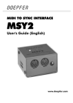
1
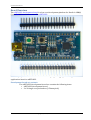
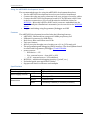
www.mommosoft.com BLE DEV.N User manual 1 January , 2014 v1.1 Copyright © 2014, Mommosoft Ltd www.mommosoft.com Table of Contents BOARD OVERVIEW 4 DEVELOPMENT BOARD SET CONTENTS USING THE NRF51822 DEVELOPMENT BOARD FEATURES SPECIFICATIONS 4 5 5 5 HARDWARE DESCRIPTION 6 FUNCTIONAL DESCRIPTION MICROCONTROLLER USB DEVICE USER SWITCHES AND USER LEDS HEADERS POWER MANAGEMENT POWER SUPPLIES CLOCKING RESET DEBUGGER INTERFACE (DIF) 6 6 6 7 8 8 8 9 9 9 SOFTWARE DEVELOPMENT 9 SOFTWARE DESCRIPTION SOURCE CODE TOOL OPTIONS PROGRAMMING THE NRF51822 DEVELOPMENT BOARD 9 9 9 9 REFERENCES, PCB LAYOUT, AND BILL OF MATERIALS 10 REFERENCES COMPONENT LOCATIONS 10 10 SCHEMATICS 11 2 Copyright © 2014, Mommosoft Ltd www.mommosoft.com BOARD OVERVIEW 4 DEVELOPMENT BOARD SET CONTENTS ...................................................................................................................... 4 USING THE NRF51822 DEVELOPMENT BOARD ........................................................................................................ 5 FEATURES .................................................................................................................................................................... 5 SPECIFICATIONS ........................................................................................................................................................... 5 HARDWARE DESCRIPTION 6 FUNCTIONAL DESCRIPTION ......................................................................................................................................... 6 MICROCONTROLLER ......................................................................................................................................................................... 6 USB DEVICE ....................................................................................................................................................................................... 6 USER SWITCHES AND USER LEDS .................................................................................................................................................. 7 HEADERS ............................................................................................................................................................................................ 8 POWER MANAGEMENT ................................................................................................................................................ 8 POWER SUPPLIES .............................................................................................................................................................................. 8 CLOCKING ........................................................................................................................................................................................... 9 RESET .................................................................................................................................................................................................. 9 DEBUGGER INTERFACE (DIF) .................................................................................................................................... 9 SOFTWARE DEVELOPMENT 9 SOFTWARE DESCRIPTION ........................................................................................................................................... 9 SOURCE CODE .............................................................................................................................................................. 9 TOOL OPTIONS ............................................................................................................................................................ 9 PROGRAMMING THE NRF51822 DEVELOPMENT BOARD ......................................................................................... 9 REFERENCES, PCB LAYOUT, AND BILL OF MATERIALS 10 REFERENCES ............................................................................................................................................................. 10 COMPONENT LOCATIONS ......................................................................................................................................... 10 SCHEMATICS 11 3 Copyright © 2014, Mommosoft Ltd www.mommosoft.com Board Overview The nRF51822 development board is a low-‐cost development platform for Nordic’s ARM® Cortex™ -‐ M0-‐based microcontroller nRF51822. The main purpose of the board is to accelerate designing, debugging and testing of software applications based on nRF51822. Development board set contents The nRF51822 development board set contains the following items: • nRF51822 development board • 2 x 20 single row pin headers (2.54mm pitch) 4 Copyright © 2014, Mommosoft Ltd www.mommosoft.com Using the nRF51822 development board The recommended steps for using the nRF51822 development board are: • Put the nRF51822 development board on your favorite breadboard • Connect the other necessary elements from your project to board by cables • Connect the nRF51822 development board to PC by USB mini cable. If this is the first connection to PC you will be asked to install the driver for MCP2200 -‐ Microchip’s USB-‐to-‐UART serial converter embedded into the board. Usually the installation is automatic. Just in case this is the MCP2200 driver. • Program and debug using Programmer/Debugger and IDE Features The nRF51822 development board includes the following features: • nRF51822 -‐ Bluetooth low energy and 2.4GHz proprietary SoC • USB mini-‐B connector for USB device • Red, Green, Blue and Yellow user LEDs • Two user buttons • All SoC port pins brought out to headers on a 0.1-‐in (2.54-‐mm) grid • The programming and debugging (SWD) interface. The development board is tested with Programmer/Debugger J-‐Link LITE ARM. • power sources: − USB device – +5V − Vin -‐ external source – from 4.8V to 30V − +3.3V -‐ external source +3.3V stabilized • MCP2200 – additional debugging interface (“printf”, etc.) • Preloaded quick start application “blinky” • Supports all Nordic’s software and examples Specifications Parameter Board supply voltage Board supply current Dimensions 1 LED on + LED on Value 4.8V to 30V ~5mA + 5mA per LED board 61mm x 27mm holes 2200mils(55.88mm) x 900mils(22.86mm) 5 Copyright © 2014, Mommosoft Ltd www.mommosoft.com Hardware Description The block diagram in Figure 2-1 shows the main peripheral features of the development board. This chapter describes how these peripherals operate and interface to the microcontroller. PCB antenna Tx MCP2200 USB to U ART bridge to P1, P2 P1 nRF51822 SoC Programmer/debugger SWD connector SWDCLK GPIO GPIO RGBY Leds GPIO User buttons SWDIO Figure 0-‐1 P2 ... GP1,2,3,4,5 Rx ... USB mini connector Functional description Microcontroller The development board is based on Nordic’s nRF512822 SoC – an ultra-‐low power 32-‐bit ARM Cortex-‐M0-‐based microcontroller with 256-‐KB Flash memory, 8-‐KB SRAM, 16-‐MHz operation and a wide range of other peripherals. See the nRF51822 link for complete device details. All of the microcontroller port pins are routed to 0.1-‐in (2.54-‐mm) pitch connectors P1 and P2. An internal multiplexer allows different peripheral functions to be assigned to each of these GPIO pins. When adding external circuitry, consider the additional load on the evaluation board power rails. The nRF51822 microcontroller is factory-‐programmed with a quickstart demo program. The quickstart program resides in on-‐chip Flash memory and runs each time power is applied, unless the quickstart application has been replaced with a user program. USB Device The development board includes a USB mini-‐B connector to allow for USB 2.0 device operation. The Microchip’s MCP2200 USB to UART bridge is used to make connection between SoC and PC. The GPIO pin P0.06 is used to send data from SoC to bridge and P0.07 is used to send data from bridge to SoC. To use this feature the user has to make proper peripheral configuration during initialization process. If the user wants to use these pins for other purposes he may cut the connections by special cut places SB7 and SB8. The bridge MCP2200 has GPIO pins that can be configured from PC and used for debugging purposes. They are connected to the connectors as follows: 6 Copyright © 2014, Mommosoft Ltd www.mommosoft.com MCP2200 GPIO pin Header pin GP1 P2 -‐ 1 GP2 P2 -‐ 2 GP3 P1 -‐ 6 GP4 P1 -‐ 5 GP5 P1 -‐ 4 When connected as an USB device, the development board can be powered from either the USB connector or the external sources Figure 0-‐2. User switches and user LEDs The nRF51822 development board comes with Red, Green, Blue and Yellow LEDs. These LEDs can be configured for use in custom user applications. They are connected to the following GPIO pins by cutting places: LED GPIO pin Cutting place Blue P0.27 SB4 Yellow P0.28 SB3 Red P0.29 SB2 Green P0.30 SB1 Two user buttons are included on the board. The user buttons can be configured for use in custom user applications. They are connected to the following GPIO pins by cutting places: Button GPIO pin Cutting place Green, SW1 P0.05 SB5 Black, SW2 P0.04 SB6 If the user wants to use these pins for other purposes he may cut the connections by the cutting places. The evaluation board also has a green power LED. 7 Copyright © 2014, Mommosoft Ltd www.mommosoft.com Headers There are two rows of 20 holes on the board. They form connectors labeled P1 and P2. The set contains two 20 pin headers that can be soldered to these connectors. This is useful for working with breadboards or for stacking. The connector P3 is for programming / debugging by SWD interface. The connector P4 is for cutting SoC power and doing hardware reset (nRF51822 has not reset pin during debugging). Power Management Power Supplies Figure 0-‐2 The power supply scheme is as shown in Figure 0-‐2. The LP2950 is used to stabilize the voltage to 3.3V -‐ the supply voltage for SoC nRF51822. The nRF51822 development board can be supplied with power by 4 sources: • USB – when the development board is connected to USB port by cable. +5V from Vbus is used as power source for development board. Keep in mind that usually the normal USB port provides up to 100mA. • Vin – this can be any external unstabilized or stabilized DC voltage source. The voltage must be between 4.3V and 30V. If the development board is connected to USB port or has power +5V and the voltage applied to Vin is >5V the board will be powered by Vin. If Vin is <5V -‐ the board will be powered by USB or +5V; • +5V -‐ this is the Vbus from USB. The user can use this pin to power other elements with +5V. If there is not connection with USB this pin is equal to Vin and can be used to power the board in same way. 8 Copyright © 2014, Mommosoft Ltd www.mommosoft.com • +3.3V – this is the output LP2950. The user can use this pin to power other elements with +3.3V. If no other power sources connected to board this pin can be used to power the board with +3.3V from external stabilized source. Clocking The development board uses a 16.0-‐MHz crystal only to complete the SoC main internal clock circuit. Note: The 16.0-‐MHz crystal has to be selected in sources for all of the Nordic Bluetooth (ble) examples to work. Code change Clock source needs to be NRF_CLOCK_LFCLKSRC_SYNTH_250_PPM when you call SOFTDEVICE_HANDLER_INIT macro SOFTDEVICE_HANDLER_INIT(NRF_CLOCK_LFCLKSRC_SYNTH_250_PPM,… If the user plans to use 32.768 kHz crystal it can be added using pins from connector P2 – pin 14 (P0.27) and pin 15 (P0.26). The Pin P0.27 must be cut from Blue LED circuitry by cutting place. Reset As it is described in “nRFF51 Series Reference Manual” the pins SWDIO and nRESET share the same physical pin. This means that in Debug mode the only way for full reset is removing and re-‐applying voltage to the chip. This can be done by removing jumper from connector P4 and putting it back. Debugger Interface (DIF) The programming/debugging of SoC can be done by Serial wire Debug (SWD) interface (connector P3). Software Development Software Description Source Code Tool Options Programming the nRF51822 development board 9 Copyright © 2014, Mommosoft Ltd www.mommosoft.com References, PCB Layout, and Bill of Materials References The following useful references are available for download: − nRF51822 overview; − other useful downloads from Nordic − Microchip's MCP2200 USB-‐to-‐UART serial converter − voltage regulator LP2950 Component Locations 10 Copyright © 2014, Mommosoft Ltd www.mommosoft.com Schematics 11 Copyright © 2014, Mommosoft Ltd