1
K5299V2 7/03
5869
Holdup Switch/Transmitter
INSTALLATION AND SETUP GUIDE
GENERAL INFORMATION
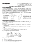
The 5869 Holdup Switch/Transmitter is a finger-operated
RF transmitting device used for activating a holdup signal
at the security system control, and/or any other security
application. The 5869 is typically mounted under a counter
or money draw for inconspicuous operation. When the
transmitter is activated, it sends an RF signal to the control
panel, which then sends a burglary alarm to the central
station.
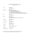
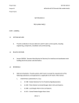
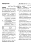
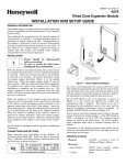
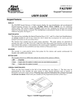
Once the 5869 trigger (Figure 1) is activated, the supplied
reset key K4563 must be used to reset the device. The 5869
also contain tamper switches that are activated either when
the cover is removed, or when the unit is forcibly removed
from its installation location.
The 5869 has a permanent serial number assigned during
manufacture used for enrolling the 5869 with the security
system control panel. To enroll the 5869, refer to the
respective Security System Control Panel Installation and
Setup Guide.
For certified UL installations, the 5869 must be used
with the 5881ENHC tamper-protected wireless
receiver, mounted inside its plastic enclosure and
outside the alarm panel enclosure.
RESET
KEY
COVER
ATTACH
HOLE
MOUNTING
HOLE
(TYP.)
COVER
TRIGGER
COVER
SCREW (2)
No. 6X1/2
+
3V
LITHIUM
BATTERY
BREAKAWAY
TAMPER
SCREW
No. 6X3/4
+
COVER
TAMPER
SWITCH
MOUNTING
SCREW (2)
No. 6X2
ANTENNA
COVER
ATTACH
HOLE
PROGRAMMING
The 5869 Holdup Switch/Transmitter should be
programmed as a 24-hour silent zone type. Refer to the
Security System Control Panel Installation and Setup
Guide for programming instructions.
NOTES:
•
During programming of the control panel, the 5869
Holdup Switch/Transmitter should be treated as "RF"
(i.e., supervised RF) Type.
•
The 5869 is one closed input loop zone (loop 1).
COVER
SCREW (2)
No. 6X1/2
5869-002-V1
Figure 1. 5869 Holdup Switch/Transmitter Details
TRIGGER
MOUNTING
3V LITHIUM
BATTERY
+
ANTENNA
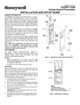
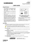
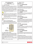
NOTE:
THE NEGATIVE ( - )
SIDE OF THE BATTERY
MUST FACE THE TRIGGER
Figure 2. 5869 Battery Installation
5869-006-V0
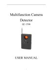
Mount the 5869 under a counter or money drawer for easy
access by the cashier. Refer to the figure and steps that
follow for typical mounting installation.
Before mounting the 5869 permanently, perform Go/No Go
tests to verify adequate transmitter signal strength at desired
mounting location (refer to the Security System Control
Panel Installation and Setup Guide).
1. Install the battery into the battery holder observing
correct polarity as shown in Figure 2.
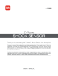
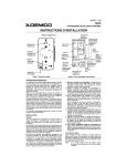
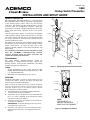
2. Position the case to the desired location and install one
No. 6 x ¾ screw (supplied) at the breakaway tamper
release hole as shown in Figure 3.
3. Secure the cover to the case with the two screws (No 6 x
1/2) as shown in Figure 3.
IMPORTANT: To prevent damage to the case, do not
over tighten the cover screws.
4. Secure the case with the cover to its mounting location
using the two screws (No. 6 x 2) supplied as shown in
Figure 3.
3.
Observing correct polarity (negative side of the battery
facing the trigger), insert the battery into the battery
holder as shown in Figure 1.
4.
Re-install two cover screws and two mounting screws as
shown in Figure 1.
SPECIFICATIONS
Physical
MOUNTING
HOLE
+
Battery
3-volt Lithium. ADEMCO 466, Duracell
DL123A, Panasonic CR123A, Sanyo CR123A,
Varta CR123A, or equivalent.
Frequency
345MHz
Reset Key:
Supplied, Part Number K4563 to order
separately
Agency:
UL 636 – Holdup alarm units and systems
+
MOUNTING
HOLE
BREAKAWAY
TAMPER
SCREW
No. 6X3/4
COVER
SCREW (2)
No. 6x1/2
COVER
SCREW (2)
No. 6x1/2
MOUNTING
SCREW (2)
No. 6X2
5869-004-V0
MOUNTING
SCREW (2)
No. 6X2
1-15/16"W x 5-15/16"H x 1-3/16"D
(50mm x 150mm x 30mm)
IMPORTANT:
THIS DEVICE MUST BE PERMANENTLY
MOUNTED WITH THE SCREWS SUPPLIED.
Figure 3. Typical Holdup Switch Installation
BATTERY REPLACEMENT
BATTERY CAUTION:
Risk of fire, explosion, and burns. Do not recharge, disassemble, heat above 100°C, or incinerate. Dispose of used
batteries promptly and properly. Keep away from children.
C
R
US
LISTED
IMPORTANT: When servicing the device for battery
replacement, note that with the mounting screws
removed the case is held in place by the tamper release
tab. Exercise caution not to jar the case while replacing
the battery, possibly breaking the Tamper breakaway
tab.
1.
Remove the two screws securing the cover and two
mounting screws as shown in figure 1.
NOTE: Use care not to bend the antenna while
attempting to remove or install the battery.
2.
Remove faulty battery and dispose of properly.
TO THE INSTALLER
Regular maintenance and inspection (at least annually) by the installer and frequent testing by the user are
vital to continuous satisfactory operation of any alarm system.
The installer should assume the responsibility of developing and offering a regular maintenance program to
the user, as well as acquainting the user with the proper operation and limitations of the alarm system and its
component parts. Recommendations must be included for a specific program of frequent testing (at least
weekly) to insure the system's operation at all times.
2
FCC ID: CFS8DL5869
This device complies with Part 15 of the FCC Rules. Operation is subject to the
following two conditions: (1) This device may not cause harmful interference, and (2)
this device must accept any interference received, including interference that may cause
undesired operation.
FEDERAL COMMUNICATIONS COMMISSION (FCC) STATEMENT
This equipment has been tested to FCC requirements and has been found acceptable for use. The FCC
requires the following statement for your information:
This equipment generates and uses radio frequency energy and if not installed and used properly, that is, in
strict accordance with the manufacturer's instructions, may cause interference to radio and television
reception. It has been type tested and found to comply with the limits for a Class B computing device in
accordance with the specifications in Part 15 of FCC Rules, which are designed to provide reasonable protection
against such interference in a residential installation. However, there is no guarantee that interference will
not occur in a particular installation. If this equipment does cause interference to radio or television reception,
which can be determined by turning the equipment off and on, the user is encouraged to try to correct the
interference by one or more of the following measures:
• If using an indoor antenna, have a quality outdoor antenna installed.
• Reorient the receiving antenna until interference is reduced or eliminated.
• Move the radio or television receiver away from the receiver/control.
• Move the antenna leads away from any wire runs to the receiver/control.
• Plug the receiver/control into a different outlet so that it and the radio or television receiver are on different
branch circuits.
If necessary, the user should consult the dealer or an experienced radio/television technician for additional
suggestions. The user or installer may find the following booklet prepared by the Federal Communications
Commission helpful:
"Interference Handbook"
This booklet is available under Stock No. 004-000-00450-7 from the U.S. Government Printing Office,
Washington, DC 20402.
The user shall not make any changes or modifications to the equipment unless authorized by the Installation
Instructions or User's Manual. Unauthorized changes or modifications could void the user's authority to
operate the equipment.
3
ADEMCO LIMITED WARRANTY
Honeywell International Inc., acting through its ADEMCO business ("Seller"), 165 Eileen Way, Syosset, New York
11791, warrants its product(s) to be in conformance with its own plans and specifications and to be free from defects
in materials and workmanship under normal use and service for 24 months from the date stamp control on the
product(s) or, for product(s) not having an ADEMCO date stamp, for 12 months from date of original purchase unless
the installation instructions or catalog sets forth a shorter period, in which case the shorter period shall apply. Seller's
obligation shall be limited to repairing or replacing, at its option, free of charge for materials or labor, any product(s)
which is proved not in compliance with Seller's specifications or proves defective in materials or workmanship under
normal use and service. Seller shall have no obligation under this Limited Warranty or otherwise if the product(s) is
altered or improperly repaired or serviced by anyone other than ADEMCO factory service. For warranty service,
return product(s) transportation prepaid, to ADEMCO Factory Service, 165 Eileen Way, Syosset, New York 11791.
THERE ARE NO WARRANTIES, EXPRESS OR IMPLIED, OF MERCHANTABILITY, OR FITNESS FOR A
PARTICULAR PURPOSE OR OTHERWISE, WHICH EXTEND BEYOND THE DESCRIPTION ON THE FACE
HEREOF. IN NO CASE SHALL SELLER BE LIABLE TO ANYONE FOR ANY CONSEQUENTIAL OR INCIDENTAL
DAMAGES FOR BREACH OF THIS OR ANY OTHER WARRANTY, EXPRESS OR IMPLIED, OR UPON ANY
OTHER BASIS OF LIABILITY WHATSOEVER, EVEN IF THE LOSS OR DAMAGE IS CAUSED BY THE SELLER'S
OWN NEGLIGENCE OR FAULT.
Seller does not represent that the product(s) it sells may not be compromised or circumvented; that the product(s) will
prevent any personal injury or property loss by burglary, robbery, fire or otherwise; or that the product(s) will in all
cases provide adequate warning or protection. Customer understands that a properly installed and maintained alarm
system may only reduce the risk of a burglary, robbery, fire, or other events occurring without providing an alarm, but
it is not insurance or a guarantee that such will not occur or that there will be no personal injury or property loss as a
result. CONSEQUENTLY, SELLER SHALL HAVE NO LIABILITY FOR ANY PERSONAL INJURY, PROPERTY
DAMAGE OR OTHER LOSS BASED ON A CLAIM THAT THE PRODUCT(S) FAILED TO GIVE WARNING.
HOWEVER, IF SELLER IS HELD LIABLE, WHETHER DIRECTLY OR INDIRECTLY, FOR ANY LOSS OR DAMAGE
ARISING UNDER THIS LIMITED WARRANTY OR OTHERWISE, REGARDLESS OF CAUSE OR ORIGIN,
SELLER'S MAXIMUM LIABILITY SHALL NOT IN ANY CASE EXCEED THE PURCHASE PRICE OF THE
PRODUCT(S), WHICH SHALL BE THE COMPLETE AND EXCLUSIVE REMEDY AGAINST SELLER.
This warranty replaces any previous warranties and is the only warranty made by Seller on this product(s). No
increase or alteration, written or verbal, of the obligations of this Limited Warranty is authorized.
165 Eileen Way, Syosset, NY 11791
www.ademco.com
Copyright © 2003 Honeywell International Inc.
¬.9al
K5299V2 7/03