1
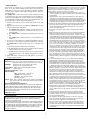
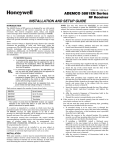
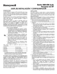
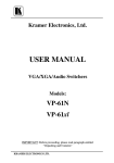
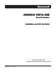
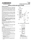
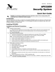
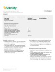
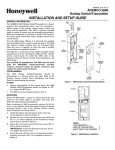
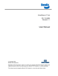
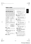
N7635-3V4 11/08 Rev. B ADEMCO 5881EN Series RF Receiver INSTALLATION AND SETUP GUIDE INTRODUCTION The 5881EN Series of RF receivers is designed for use with control panels that support an RF receiver connection via the keypad terminals. The receiver recognizes alarm, status, and keypad control messages from wireless transmitters operating at 345MHz. One or two individually identified receivers can be employed, depending on the control used. Connection of multiple receivers to a control can provide redundant coverage or extend coverage in large areas. These receivers feature a Spatial Diversity System that virtually eliminates the possibility of "nulls" and "dead spots" within the coverage area. The 5881EN series of receivers use ADEMCO’s High Security technology, and can be used in commercial fire installations. Additionally, the 5881ENHC receiver contains front and back tamper that permits its use in commercial burglary and fire installations. For 5881ENHC Receivers: • In commercial fire applications, the receiver can only be used with control panels that are approved for use in Commercial Fire Installations. When the 5881ENHC is used in commercial fire applications, DIP switch 5 must be in the ON position. UL • In commercial burglary applications, the 5881ENHC can only be used with control panels that are approved for use in Commercial Burglary Installations. • In commercial fire applications, a keypad must be connected to Keypad Port 2 in the control. The keypad must be mounted on the control or within 3 feet of the control with the wiring encased in conduit. • All power-limited wiring must be separated from nonpower limited and high-voltage wiring by ¼" (6.4mm). Each receiver supports the number of zones shown below. 5881ENL Up to 8 zones 5881ENM Up to 16 zones 5881ENH *See below 5881ENHC *See below * The number of zones that the 5881ENH receiver can support depends on the control with which it is used. See the control panel’s instructions for specific details. If a receiver is connected to a system in which more than the permitted number of wireless zones have been programmed, a "SET UP ERROR" message (on alpha keypads) or an "E4 or “E8”" message (on fixed-word keypads) will be displayed on the system's keypad, and none of the zones will be protected. The instruction manual that accompanies the control includes recommendations regarding receiver and transmitter locations, the types of wireless zones that can be programmed (e.g., ENTRY/EXIT, PERIMETER, INTERIOR, etc.) and the procedure for programming the receivers. These receivers should not be installed in an area subject to environmental extremes of below freezing (such as an unheated warehouse) or extremely high temperatures (such as an attic). INSTALLATION With some controls, a receiver may be mounted directly inside the control's cabinet (receiver circuit board only, without its plastic housing) instead of remotely (in its own housing). In both cases, avoid mounting the receiver antennas against a metal surface. NOTE: You may only mount the 5881ENHC its own plastic housing. If you attempt to mount the 5881ENHC in the control’s cabinet, the receiver constantly reports a tamper condition. 1. Remove the receiver's cover by inserting a screwdriver blade in the slot at the center of the cover's lower edge. 2. If the receiver is to be mounted within the control's cabinet (refer to Figure 1): a. Remove the receiver's circuit board from its base by bending back the two flexible plastic tabs that hold the board's lower edge. b. In the control's cabinet, unfasten and move the control circuit board downward (if already installed). c. Hang two mounting clips (provided with the receiver) on the raised cabinet tabs, as shown in Detail B of Figure 1. d. Insert the top of the receiver board between the rows of slots at the top of the cabinet, as shown in Detail A. e. Position the base of the receiver board onto the mounting clips and secure to the cabinet with the supplied screws. See Detail B. f. Hang two mounting clips (supplied with the control board), on the raised cabinet tabs as shown in Detail C in Figure 1. g. Insert the top of the control board into the slots of the mounting clips secured in step e above. h. Position the lower end of the control board into place on the mounting clips and secure both to the cabinet with the two supplied screws. i. Insert both grounding lugs (supplied with the receiver) through the top of the cabinet into the left-hand terminals of the antenna blocks (located on the upper edge of the receiver board), and secure them to the cabinet with the screws provided, as shown in Detail D. j. Insert the receiver’s antennas through the top of the cabinet, into the blocks’ right-hand terminals, and tighten the screws. k. Affix the receiver's Summary of Connections label to the inside of the control's cabinet door. l. Discard the receiver's unused plastic cover and base. 3. If the receiver is to be located remotely from the control in its own plastic enclosure (not in a cabinet): You will not need the circuit board mounting clips, grounding lugs and screws included with the receiver. a. If concealed wiring is to be used, route it through the rectangular opening at the rear of the base before mounting. For surface wiring entry, a thin breakaway area is provided along the base's right edge. b. Mount the receiver in the selected location. For greatest security, use all four mounting holes (two key slot holes and two round holes) provided in the plastic base. c. If installing a 5881ENHC, install a flat-head screw (supplied) in the case tamper tab as shown in Figure 2. When the receiver is pried from the wall, the tamper tab will break off and remain on the wall. This will activate a tamper switch in the receiver and cause generation of a tamper signal. Note that this signal will also be generated when the receiver’s front cover is removed. d. Affix the receiver's Summary of Connections label to the inside of the housing cover. HOLES FOR ANTENNAS AND GROUNDING LUGS CABINET CIRCUIT BOARD BOARD SUPPORTING SLOTS RECEIVER CIRCUIT BOARD (See Detail D) + DETAIL A SIDE VIEW OF BOARD SUPPORTING SLOTS + MOUNTING CLIP CONTROL CIRCUIT BOARD SCREW MOUNTING CLIP 5881ENHC-001-V0 SCREW (2) GROUNDING LUG (2) ANTENNA (2) DETAIL B SIDE VIEW OF MOUNTING CLIP Figure 2: Tamper Protection FRONT TAMPER (REAR TAMPER) CABINET DETAIL C SIDE VIEW OF MOUNTING CLIP RCVR BRD + + ECP CONNECTION ANTENNA MOUNT (2 PLACES) MOUNTING HOLES 4 (TYP) DETAIL D ANTENNA AND GROUNDING LUG INSTALLATION pcb_RF_mount-V0 Figure 1: Installing the Receiver Board in the Control’s Cabinet MACHINE SCREWS 4 (TYP) 4. Setting the DIP switches (All Receivers): a. Set the receiver's DIP switch (#2 through #4) to identify the receiver's address (refer to the DIP switch chart in the Summary of Connections Diagram on back cover). b. Verify that DIP switch #1 is in the OFF position. c. Set DIP switch #5 according to the following chart. DIP SWITCH #5 For . . . Set to . . . Commercial Fire Applications ON Non-commercial Fire Applications OFF NOTES: • If multiple receivers are used on one control, DIP switch #5 must be set to the same position on all receivers. • DIP switch #5 reduces sensitivity during supervision message reception. For commercial fire applications, DIP switch #5 must be in the ON position. 5. Insert the wiring plug (with 4 flying leads) into the mating socket on the receiver (see Summary of Connections Diagram on back cover for socket location). Connect the 4 wires to the control's corresponding keypad terminals (see “Interface Wiring” in the SPECIFICATIONS section). 6. Install the antennas in the right-hand terminals of the two terminal blocks at the upper edge of the circuit board, one into each block’s right-hand terminal, and tighten the screws to secure them. Caution: Avoid mounting the receiver antennas against a metal surface. 7. Replace the unit's front cover using the supplied screw to secure it. 8. Proceed with any programming of the control that may be necessary for RF operation, and the installation of the system's wireless transmitters, as described in the control's installation and setup guide and the transmitter's installation instructions. NOTES: • The receiver can support up to 16 high security (encrypted) wireless transmitters (keys). The total quantity of wireless keys (encrypted and unencrypted) that can be used is determined by the control panel. • Wireless key buttons must be enrolled to zones in the control panel via zone programming first. If the wireless key is to be used for arming and disarming the VISTA-40 and up, a user number must then be assigned to the wireless key via user programming. If it is not done in this order, you will be unable to respond successfully to the RF button zone number prompt in user programming. • If more than one receiver is being used and you are using encrypted wireless keys, we recommend that you (a) enter the GO/NO GO mode, (b) disconnect one receiver, (c) enroll all encrypted keys into the connected receiver, (d) reconnect the disconnected receiver, (e) exit the GO/NO GO mode, and then PLASTIC CONDUIT COVER SECURING SCREWS 5883HC-001-V0 Figure 3: 5881ENHC UL Commercial Fire Installation (f) repeat (a) through (e) for the receiver that was disconnected. • The RED LED located on the receiver's circuit board should be used as an indicator of strong local radio frequency interference. If this LED is continuously illuminated, the receiver should be relocated. • After a successful enrollment of an encrypted key, the GREEN LED blinks the number of spaces that are free for additional encrypted key enrollment. 9. Replace the receiver's cover. UL Commercial Fire Installation For UL864 Commercial Fire Installations, you will need to purchase separately the "5800BOX" (in which the circuit board will be installed). Follow the instructions below and refer to Figure 3. 1. Mount the rear half of the 5800BOX directly to the wall in the selected location, hinged side up. Secure using the 4 screws provided and insert screw in tamper tab, refer to Installation, step 3c and Fig. 2. 2. Thread the ECP wire through the conduit and feed through the opening at the side of the box rear. 3. Remove the circuit board from the 5881EN case and discard case. Install the circuit board into the 5800BOX and secure using the 4 screws provided. Install each antenna, refer to Installation: Step 6. 4. Connect the ECP terminals as shown. 5. Insert slots on top of box cover into hinges on top of box back and secure using 2 cover securing screws. 5800 SERIES WIRELESS TRANSMITTERS CONTROL PANEL* ECP ISOLATOR TO BURGLARY DEVICES KEYPAD TERMINALS ON CONTROL BOARD 2-WAY TRANSMISSION TO FIRE DEVICES 5881ENHC TRANSCEIVER 2-WAY WIRELESS KEYPAD (e.g. 5804BD) OR 5800RL 2-WAY RELAY MODULE *CONTROL MUST BE CAPABLE OF SUPPORTING A 5800 RF SYSTEM 5883HC-002-V0 Figure 4: Mounting UL Commercial Fire Applications NOTE: For UL-864 Fire installations, ECP Isolator (PN ECP-ISO) is required. 2 ENCRYPTED KEYS The receiver can support up to 16 encrypted wireless transmitters (keys) at one time. If the number on the receiver microprocessor is WAK 4406-4 or higher, the receiver provides you with the capability to check space available and/or delete encrypted keys using the procedures below. The GREEN LED located on the receiver's circuit board may be used to determine how many more encrypted keys may be enrolled into the receiver. This LED is also used to indicate when encrypted keys may be deleted. To determine how many more encrypted keys may be enrolled and/or to delete enrolled encrypted keys: 1. Remove power from the receiver and set DIP switch 1 to the ON position. 2. Apply power to the receiver and watch the GREEN LED. You will see one of the following indications: a. The GREEN LED blinks the number of spaces that are free for additional encrypted key enrollment and then goes to constantly ON. b. The GREEN LED is constantly ON, indicating the receiver is full. c. The GREEN LED is OFF, indicating no encrypted keys are enrolled. 3. If you do not want to delete any enrolled encrypted keys, advance to step 4. If you want to delete enrolled encrypted keys, wait until the GREEN LED is constantly ON in step 2 a. or 2 b. above and then: a. Record the positions of DIP switches 1 through 5. b. Set DIP switches 1 through 5 to the opposite positions of their current settings and wait a few moments. c. Set DIP switches 1 through 5 back to their original positions as recorded in step a. All enrolled encrypted keys will be deleted. 4. Place DIP switch 1 back into the OFF position to return to normal receiver operation. WARNING! LIMITATIONS OF THIS WIRELESS ALARM SYSTEM While this System is an advanced wireless security system, it does not offer guaranteed protection against burglary, fire or other emergency. Any alarm system, whether commercial or residential, is subject to compromise or failure to warn for a variety of reasons. For example: • Intruders may gain access through unprotected openings or have the technical sophistication to bypass an alarm sensor or disconnect an alarm warning device. • Intrusion detectors (e.g., passive infrared detectors), smoke detectors, and many other sensing devices will not work without power. Batteryoperated devices will not work without batteries, with dead batteries, or if the batteries are not put in properly. Devices powered solely by AC will not work if their AC power supply is cut off for any reason, however briefly. • Signals sent by wireless transmitters may be blocked or reflected by metal before they reach the alarm receiver. Even if the signal path has been recently checked during a weekly test, blockage can occur if a metal object is moved into the path. • A user may not be able to reach a panic or emergency button quickly enough. • While smoke detectors have played a key role in reducing residential fire deaths in the United States, they may not activate or provide early warning for a variety of reasons in as many as 35% of all fires, according to data published by the Federal Emergency Management Agency. Some of the reasons smoke detectors used in conjunction with this System may not work are as follows. Smoke detectors may have been improperly installed and positioned. Smoke detectors may not sense fires that start where smoke cannot reach the detectors, such as in chimneys, in walls, or roofs, or on the other side of closed doors. Smoke detectors also may not sense a fire on another level of a residence or building. A second floor detector, for example, may not sense a first floor or basement fire. Finally, smoke detectors have sensing limitations. No smoke detector can sense every kind of fire every time. In general, detectors may not always warn about fires caused by carelessness and safety hazards like smoking in bed, violent explosions, escaping gas, improper storage of flammable materials, overloaded electrical circuits, children playing with matches, or arson. Depending on the nature of the fire and/or location of the smoke detectors, the detector, even if it operates as anticipated, may not provide sufficient warning to allow all occupants to escape in time to prevent injury or death. • Passive Infrared Motion Detectors can only detect intrusion within the designed ranges as diagrammed in their installation manual. Passive Infrared Detectors do not provide volumetric area protection. They do create multiple beams of protection, and intrusion can only be detected in unobstructed areas covered by those beams. They cannot detect motion or intrusion that takes place behind walls, ceilings, floors, closed doors, glass partitions, glass doors, or windows. Mechanical tampering, masking, painting or spraying of any material on the mirrors, windows or any part of the optical system can reduce their detection ability. Passive Infrared Detectors sense changes in temperature; however, as the ambient temperature of the protected area approaches the temperature range of 90° to 105°F (32° to 40°C), the detection performance can decrease. • Alarm warning devices such as sirens, bells or horns may not alert people or wake up sleepers if they are located on the other side of closed or partly open doors. If warning devices are located on a different level of the residence from the bedrooms, then they are less likely to waken or alert people inside the bedrooms. Even persons who are awake may not hear the warning if the alarm is muffled by noise from a stereo, radio, air conditioner or other appliance, or by passing traffic. Finally, alarm warning devices, however loud, may not warn hearing-impaired people. • Telephone lines needed to transmit alarm signals from a premises to a central monitoring station may be out of service or temporarily out of service. Telephone lines are also subject to compromise by sophisticated intruders. • Even if the system responds to the emergency as intended, however, occupants may have insufficient time to protect themselves from the emergency situation. In the case of a monitored alarm system, authorities may not respond appropriately. • This equipment, like other electrical devices, is subject to component failure. Even though this equipment is designed to last as long as 20 years, the electronic components could fail at any time. • The most common cause of an alarm system not functioning when an intrusion or fire occurs is inadequate maintenance. This alarm system should be tested weekly to make sure all sensors and transmitters are working properly. The security console (and remote keypad) should be tested as well. SPECIFICATIONS Dimensions: 7-3/8" W x 4-3/8" (10-7/8” w/antenna) H x 1-7/16" D 188mm W x 112mm H (277mm w/antenna) x 37mm D 5800BOX: 10.86 W x 5.41 (11.9 w/antenna) H x 2.24 D 276mm W x 137.5mm H x 57mm D Input Voltage: 12VDC (from control’s keypad terminals) Current: 60mA (typical) Operating Temperature: 0-50°C Interface Wiring: RED 12VDC input (+) Aux. Power GREEN: Data Out to Control YELLOW: Data In from Control BLACK: Ground (–) Range: 200ft (60m) nominal indoors from wireless transmitters (the actual range to be determined with the security system in the Test mode). Receiver Sensitivity & Noise Rejection: Receiver sensitivity and noise rejection are dynamically adjusted to match ambient conditions. Unacceptably high noise levels or low signal levels are indicated at the control panel. For test procedure, refer to the Installation & Setup Guide for the control panel with which this device is used. NFPA-72 Compliant TO THE INSTALLER Regular maintenance and inspection (at least annually) by the installer and frequent testing by the user are vital to continuous satisfactory operation of any alarm system. The installer should assume the responsibility of developing and offering a regular maintenance program to the user, as well as acquainting the user with the proper operation and limitations of the alarm system and its component parts. Recommendations must be included for a specific program of frequent testing (at least weekly) to insure the system's operation at all times. 3 Limitations of this Wireless Alarm System, Continued This system's wireless transmitters are designed to provide long battery life under normal operating conditions. Longevity of batteries may be as much as 7 years, depending on the environment, usage, and the specific wireless device being used. External factors such as humidity, high or low temperatures, as well as large swings in temperature, may all reduce the actual battery life in a given installation. This wireless system, however, can identify a true low battery situation, thus allowing time to arrange a change of battery to maintain protection for that given point within the system. Installing an alarm system may make the owner eligible for a lower insurance rate, but an alarm system is not a substitute for insurance. Homeowners, property owners and renters should continue to act prudently in protecting themselves and continue to insure their lives and property. We continue to develop new and improved protection devices. Users of alarm systems owe it to themselves and their loved ones to learn about these developments. FEDERAL COMMUNICATIONS COMMISSION (FCC) STATEMENTS The user shall not make any changes or modifications to the equipment unless authorized by the Installation Instructions or User's Manual. Unauthorized changes or modifications could void the user's authority to operate the equipment. CLASS B DIGITAL DEVICE STATEMENT NOTE: This equipment has been tested and found to comply with the limits for a Class B digital device, pursuant to part 15 of the FCC Rules. These limits are designed to provide reasonable protection against harmful interference in a residential installation. This equipment generates, uses and can radiate radio frequency energy and, if not installed and used in accordance with the instructions, may cause harmful interference to radio communications. However, there is no guarantee that interference will not occur in a particular installation. If this equipment does cause harmful interference to radio or television reception, which can be determined by turning the equipment off and on, the user is encouraged to try to correct the interference by one or more of the following measures: • Reorient or relocate the receiving antenna. • Increase the separation between the equipment and receiver. • Connect the equipment into an outlet on a circuit different from that to which the receiver is connected. • Consult the dealer or an experienced radio/TV technician for help. INDUSTRY CANADA (IC) STATEMENTS This device complies with RSS210 of Industry Canada. Operation is subject to the following two conditions: (1) This device may not cause harmful interference, and (2) This device must accept any interference received, including interference that may cause undesired operation. This Class B digital apparatus complies with Canadian ICES-003. Cet appareil numérique de la classe B est conforme à la norme NMB-003 du Canada. ANTENNAS CIRCUIT BOARD NOTE: WHEN CIRCUIT BOARD IS MOUNTED IN CONTROL'S CABINET, GROUNDING LUGS (2) PROVIDED MUST BE INSERTED IN LEFT-HAND TERMINALS OF ANTENNA BLOCKS AND SECURED TO CABINET (SEE RECEIVER'S AND CONTROL'S INSTRUCTIONS). WHEN BOARD IS MOUNTED IN A SEPARATE CABINET (COMMERCIAL FIRE APPLICATION), DO NOT USE THE GROUNDING LUGS. TO RELEASE CIRCUIT BOARD, BEND BACK BOTTOM TABS (2). FOR COMMERCIAL FIRE APPLICATION. USE TWO SCREWS (NOT SUPPLIED) WITH INSULATING WASHERS BENEATH THE HEADS. TO MOUNT BOARD IN SEPARATE CABINET. (SEE RECEIVER'S INSTRUCTIONS). INSERT IN RIGHT-HAND TERMINALS YELLOW RED BLACK 5881EN SERIES THIS DEVICE COMPLIES WITH PART 15 OF FCC RULES AND RSS210 OF INDUSTRY CANADA. OPERATION IS SUBJECT TO THE FOLLOWING TWO CONDITIONS: (1) THIS DEVICE MAY NOT CAUSE HARMFUL INTERFERENCE, AND (2) THIS DEVICE MUST ACCEPT ANY INTERFERENCE RECEIVED, INCLUDING INTERFERENCE THAT MAY CAUSE UNDESIRED OPERATION. USE MAX. OF 220 ft. (67m) OF #22 (0.64mm) WIRE OR 550 ft. (168m) OF #18 (1mm) WIRE FOR EACH RUN. 20 ft. MAX. IN COMMERCIAL FIRE INSTALLATIONS. (SEE RECEIVER'S INSTRUCTIONS). GREEN TO CONTROL'S KEYPAD TERMINALS. EACH RECEIVER MUST BE ON INDIVIDUAL DIP SWITCH #5 HOME RUN. ON: 5881ENL MOUNTING HOLES 5881ENM WIRING OPENING OFF: 5881ENH 5881ENHC FCC ID CFS8DL5882A CANADA:17481021751A FOR USE IN COMMERCIAL FIRE APPLICATIONS. (SEE THE RECEIVER'S INSTRUCTIONS). USE IN NON-COMMERCIAL FIRE INSTALLATIONS. DIP SWITCH: WHITE AREAS = SWITCH HANDLES POSITION 2-4: DETERMINE RECEIVER'S ADDRESS PLUG & SOCKET FRONT OF PC BOARD CONSULT CONTROL'S INSTRUCTIONS FOR ADDRESS TO USE. DIP SWITCH BELOW SHOWN SET FOR ADDRESS "0". BACK OF PC BOARD DIP SWITCH SEE INTERFERENCE DETAIL A INDICATOR LED GREEN LED: NORMALLY OFF ONE SHORT FLASH - RF MESSAGE DECODED ONE LONGER FLASH - COMMAND RECEIVED FROM CONTROL FOUR FLASHES - ENCRYPTED TRANSMITTER SUCCESSFULLY ENROLLED DETAIL A FRONT AND REAR TAMPER 5881ENHC ONLY ON OFF 5 4 3 2 1 SWITCH POSITION 0 RECEIVER ADDRESS SETTINGS (“—” means “OFF”) 1 2 3 4 5 6 7 4 — ON — 3 — — ON ON — 2 — — — 5 1 (SEE TEXT ABOVE) ON — — ON — — ON ON ON ON ON ON ON MUST BE IN OFF POSITION 5881EN-SOC-V4 Summary of Connections Diagram For the latest warranty information, please go to: http://www.security.honeywell.com/hsc/resources/wa/index.html 2 Corporate Center Drive, Suite 100 P.O. Box 9040, Melville, NY 11747 Copyright 2009 Honeywell International Inc. www.security.honeywell.com ÊN7635-3V4>Š N7635-3V4 11/08 Rev. B