1
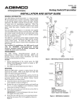
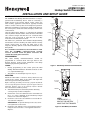
K5299V4 2/10 Rev. A
ADEMCO 5869
Holdup Switch/Transmitter
INSTALLATION AND SETUP GUIDE
GENERAL INFORMATION
The ADEMCO 5869 Holdup Switch/Transmitter is a fingeroperated RF transmitting device used for activating a
holdup signal at the security system control, and/or any
other security application. The 5869 is typically mounted
under a counter or money draw for inconspicuous operation.
When the transmitter is activated, it sends an RF signal to
the control panel, which then sends a burglary alarm to the
central station.
Once the 5869 trigger (Figure 1) is activated, the supplied
reset key K4563 must be used to reset the device. The 5869
also contains tamper switches that are activated either
when the cover is removed, or when the unit is forcibly
removed from its installation location.
The 5869 has a permanent serial number assigned during
manufacture used for enrolling the 5869 with the security
system control panel. To enroll the 5869, refer to the
respective Security System Control Panel Installation and
Setup Guide.
For certified UL installations, the 5869 must be used
with the 5881ENHC tamper-protected wireless
receiver, mounted inside its plastic enclosure and
outside the alarm panel enclosure.
RESET
KEY
COVER
ATTACH
HOLE
MOUNTING
HOLE
(TYP.)
COVER
TRIGGER
COVER
SCREW (2)
No. 6X1/2
+
3V
LITHIUM
BATTERY
BREAKAWAY
TAMPER
SCREW
No. 6X3/4
+
COVER
TAMPER
SWITCH
MOUNTING
SCREW (2)
No. 6X2
ANTENNA
COVER
ATTACH
HOLE
PROGRAMMING
The 5869 Holdup Switch/Transmitter should be
programmed as a 24-hour silent zone type. Refer to the
Security System Control Panel Installation and Setup
Guide for programming instructions.
NOTES:
•
During programming of the control panel, the 5869
Holdup Switch/Transmitter should be treated as "RF"
(i.e., supervised RF) Type.
•
The 5869 is one closed input loop zone (loop 1).
COVER
SCREW (2)
No. 6X1/2
5869-002-V1
Figure 1. 5869 Holdup Switch/Transmitter Details
TRIGGER
MOUNTING
3V LITHIUM
BATTERY
+
ANTENNA
NOTE:
THE NEGATIVE ( - )
SIDE OF THE BATTERY
MUST FACE THE TRIGGER
Figure 2. 5869 Battery Installation
5869-006-V0
Mount the 5869 under a counter or money drawer for easy
access by the cashier. Refer to the figure and steps that
follow for typical mounting installation.
Before mounting the 5869 permanently, perform Go/No Go
tests to verify adequate transmitter signal strength at desired
mounting location (refer to the Security System Control
Panel Installation and Setup Guide).
1. Install the battery into the battery holder observing
correct polarity as shown in Figure 2.
2. Position the case to the desired location and install one
No. 6 x ¾ screw (supplied) at the breakaway tamper
release hole as shown in Figure 3.
3. Secure the cover to the case with the two screws (No 6 x
1/2) as shown in Figure 3.
IMPORTANT: To prevent damage to the case, do not
over tighten the cover screws.
4. Secure the case with the cover to its mounting location
using the two screws (No. 6 x 2) supplied as shown in
Figure 3.
2.
Remove faulty battery and dispose of properly.
3.
Observing correct polarity (negative side of the battery
facing the trigger), insert the battery into the battery
holder as shown in Figure 1.
4.
Reinstall two cover screws and two mounting screws as
shown in Figure 1.
SPECIFICATIONS
MOUNTING
HOLE
Physical
1-15/16"W x 5-15/16"H x 1-3/16"D
(50mm x 150mm x 30mm)
+
MOUNTING
HOLE
+
Battery
3-volt Lithium. ADEMCO 466, Duracell
DL123A, Panasonic CR123A, Varta CR123A.
Frequency
345MHz
Reset Key:
Supplied, Part Number K4563 to order
separately
Agency:
UL 636 – Holdup alarm units and systems
BREAKAWAY
TAMPER
SCREW
No. 6X3/4
COVER
SCREW (2)
No. 6x1/2
COVER
SCREW (2)
No. 6x1/2
MOUNTING
SCREW (2)
No. 6X2
5869-004-V0
MOUNTING
SCREW (2)
No. 6X2
IMPORTANT:
THIS DEVICE MUST BE PERMANENTLY
MOUNTED WITH THE SCREWS SUPPLIED.
Figure 3. Typical Holdup Switch Installation
BATTERY REPLACEMENT
BATTERY CAUTION:
Risk of fire, explosion, and burns. Do not recharge, disassemble, heat above 100°C, or incinerate. Dispose of used
batteries promptly and properly. Keep away from children.
C
US
LISTED
IMPORTANT: When servicing the device for battery
replacement, note that with the mounting screws
removed the case is held in place by the tamper release
tab. Exercise caution not to jar the case while replacing
the battery, possibly breaking the Tamper breakaway
tab.
1.
R
Remove the two screws securing the cover and two
mounting screws as shown in figure 1.
NOTE: Use care not to bend the antenna while
attempting to remove or install the battery.
TO THE INSTALLER
Regular maintenance and inspection (at least annually) by the installer and frequent testing by the user are
vital to continuous satisfactory operation of any alarm system.
The installer should assume the responsibility of developing and offering a regular maintenance program to
the user, as well as acquainting the user with the proper operation and limitations of the alarm system and its
component parts. Recommendations must be included for a specific program of frequent testing (at least
weekly) to insure the system's operation at all times.
-2-
FCC STATEMENT
This device complies with Part 15 of the FCC Rules and RSS210 of Industry Canada.
Operation is subject to the following two conditions: (1) This device may not cause
harmful interference, and (2) this device must accept any interference received,
including interference that may cause undesired operation.
FEDERAL COMMUNICATIONS COMMISSION (FCC) PART 15 STATEMENTS
The user shall not make any changes or modifications to the equipment unless authorized by the Installation Instructions or User's Manual.
Unauthorized changes or modifications could void the user's authority to operate the equipment.
CLASS B DIGITAL DEVICE STATEMENT
NOTE: This equipment has been tested and found to comply with the limits for a Class B digital device, pursuant to part 15
of the FCC Rules. These limits are designed to provide reasonable protection against harmful interference in a residential
installation. This equipment generates, uses and can radiate radio frequency energy and, if not installed and used in
accordance with the instructions, may cause harmful interference to radio communications. However, there is no guarantee
that interference will not occur in a particular installation. If this equipment does cause harmful interference to radio or
television reception, which can be determined by turning the equipment off and on, the user is encouraged to try to correct
the interference by one or more of the following measures:
• Reorient or relocate the receiving antenna.
• Increase the separation between the equipment and receiver.
• Connect the equipment into an outlet on a circuit different from that to which the receiver is connected.
• Consult the dealer or an experienced radio/TV technician for help.
INDUSTRY CANADA (IC) STATEMENTS
This device complies with RSS210 of Industry Canada. Operation is subject to the following two conditions: (1) This device
may not cause harmful interference, and (2) This device must accept any interference received, including interference that
may cause undesired operation.
This Class B digital apparatus complies with Canadian ICES-003.
Cet appareil numérique de la classe B est conforme à la norme NMB-003 du Canada.
-3-
WARRANTY INFORMATION
For the latest warranty information, please go to:
www.honeywell.com/security/hsc/resources/wa
.
2 Corporate Center Drive, Suite 100
P.O. Box 9040, Melville, NY 11747
Copyright © 2009 Honeywell International Inc.
www.honeywell.com/security
ÊK5299V4%Š
K5299V4 2/10 Rev. A