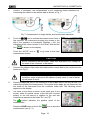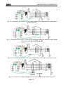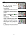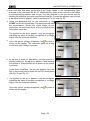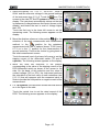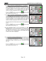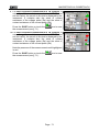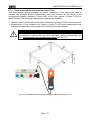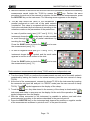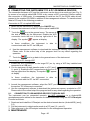
1
User manual MACROTOUCH & COMBITOUCH Copyright HT ITALIA 2015 Release EN 2.03 - 06/03/2015 MACROTOUCH & COMBITOUCH Table of contents: 1. PRECAUTIONS AND SAFETY MEASURES ............................................................... 4 1.1. 1.2. 1.3. 1.4. 2. GENERAL DESCRIPTION ........................................................................................... 5 2.1. 2.2. 3. Initial checks .................................................................................................................... 7 Instrument power supply.................................................................................................. 8 Calibration ....................................................................................................................... 8 Storage ............................................................................................................................ 8 NOMENCLATURE........................................................................................................ 8 4.1. 4.2. 4.3. 4.4. 4.5. 5. Foreword ......................................................................................................................... 6 Instrument functions ........................................................................................................ 6 PREPARATION FOR USE ........................................................................................... 7 3.1. 3.2. 3.3. 3.4. 4. Preliminary instructions.................................................................................................... 4 During use ....................................................................................................................... 4 After use .......................................................................................................................... 5 Definition of measurement (overvoltage) category ........................................................... 5 Instrument description ..................................................................................................... 9 Description of measuring leads........................................................................................ 9 Keyboard description ..................................................................................................... 10 Display description ........................................................................................................ 10 Initial screen .................................................................................................................. 10 GENERAL MENU ....................................................................................................... 11 5.1. Instrument settings ........................................................................................................ 11 5.1.1. 5.1.2. 5.1.3. 5.1.4. 5.1.5. 5.1.6. 5.2. 6. Language ............................................................................................................................... 11 Reference country .................................................................................................................. 12 Automatic Power OFF for display and key sound .................................................................. 12 System ................................................................................................................................... 12 Operator name entry .............................................................................................................. 13 System date/time setting ........................................................................................................ 13 Information .................................................................................................................... 13 OPERATING INSTRUCTIONS ................................................................................... 14 6.1. LOW: Continuity of protective conductors ................................................................... 14 6.1.1. 6.2. 6.2.1. 6.3. Test types ............................................................................................................................... 35 STD Mode – Generic test ...................................................................................................... 37 Mode kA – Verify of breaking capacity of protection device .................................................. 39 Mode I2t – Verify of protection against short-circuit ............................................................... 41 Mode - Verify of protection coordination ..................................................................... 44 Mode - Verify of protection coordination – Norvay country ......................................... 46 Verify of protection against indirect contacts (TN system) .................................................... 48 Verify of protection against indirect contacts (IT systems) .................................................... 49 Verify of protection against indirect contacts (TT systems) ................................................... 50 Impedance measurement by means of the accessory IMP57 ............................................... 53 Anomalous situations ............................................................................................................. 55 SEQ: Phase sequence and phase concordance test ..................................................... 57 6.5.1. 6.6. 6.7. AUTO mode ........................................................................................................................... 26 x½, x1, x2, x5 modes ............................................................................................................. 27 Mode x1 – Test on RCDs with delay time .............................................................................. 27 Mode ................................................................................................................................. 28 Test on earth leakage relay RCD........................................................................................... 29 Anomalous situations ............................................................................................................. 30 LOOP: Line impedance/Loop and overall earth resistance ............................................ 33 6.4.1. 6.4.2. 6.4.3. 6.4.4. 6.4.5. 6.4.6. 6.4.7. 6.4.8. 6.4.9. 6.4.10. 6.4.11. 6.5. Anomalous situations ............................................................................................................. 21 RCD: Test on differential switches ................................................................................. 22 6.3.1. 6.3.2. 6.3.3. 6.3.4. 6.3.5. 6.3.6. 6.4. Anomalous situations ............................................................................................................. 17 M: Measurement of insulation resistance .................................................................... 18 Anomalous situations ............................................................................................................. 60 LEAKAGE: Leakage current measurement.................................................................... 61 EARTH: Measurement of earth resistance..................................................................... 63 6.7.1. 3-wire or 2-wire earth measurement and 4-wire ground resistivity ........................................ 63 Page - 2 MACROTOUCH & COMBITOUCH 6.7.2. 6.7.3. 6.7.4. 6.8. 6.9. AUX: Measure of ambient parameters through external probes ..................................... 75 ΔV%: Voltage drop of main lines ................................................................................... 78 6.9.1. 6.10. 7. PQA: Real time measurement of main parameters ........................................................ 84 Saving measurements ................................................................................................... 87 Recalling measurements and deleting the memory ....................................................... 87 7.2.1. Anomalous situations ............................................................................................................. 89 CONNECTING THE INSTRUMENT TO A PC OR MOBILE DEVICES ...................... 90 8.1. 9. Anomalous situations ............................................................................................................. 82 OPERATIONS WITH THE MEMORY ......................................................................... 87 7.1. 7.2. 8. 3-wire or 2-wire earth measure – USA, Extra Europe and Germany countries ..................... 69 Earth measurement with optional clamp T2100 .................................................................... 72 Anomalous situations in 3-wire and 2-wire earth measurements .......................................... 75 Connection to iOS/Android devices through WiFi .......................................................... 90 MAINTENANCE.......................................................................................................... 90 9.1. 9.2. 9.3. 9.4. General information ....................................................................................................... 91 Replacement of the batteries ......................................................................................... 91 Cleaning the instrument ................................................................................................. 91 End of life ...................................................................................................................... 91 10. TECHNICAL SPECIFICATIONS ................................................................................ 91 10.1. 10.2. 10.3. 10.4. Technical characteristics ............................................................................................... 92 Reference guidelines ..................................................................................................... 96 General characteristics .................................................................................................. 97 Environment .................................................................................................................. 97 10.4.1. 10.5. Environmental conditions for use ........................................................................................... 97 Accessories ................................................................................................................... 97 11. SERVICE .................................................................................................................... 97 11.1. 11.2. Warranty conditions ....................................................................................................... 98 Service .......................................................................................................................... 98 12. THEORETICAL APPENDIXES ................................................................................... 98 12.1. 12.2. 12.3. 12.4. 12.5. 12.6. 12.7. 12.8. 12.9. 12.10. 12.11. 12.12. Continuity of protective conductors ................................................................................ 99 Insulation resistance ...................................................................................................... 99 Checking circuit separation .......................................................................................... 100 Test on differential switches (RCD).............................................................................. 103 Verify of the breaking capacity of protection devices ................................................... 104 Verify of protection against indirect contacts in TN systems ........................................ 105 Verify of protection against indirect contacts in TT systems ......................................... 107 Verify of protection against indirect contacts in IT systems .......................................... 108 Verify of protection coordination L-L, L-N and L-PE ..................................................... 109 Verify of the protection against short circuits – Test I2t ................................................ 111 Verification of voltage drop on main lines..................................................................... 112 Measurement of earth resistance in TN systems ......................................................... 112 12.12.1. 12.12.2. Measurement of earth impedance by voltammetric method ................................................ 113 Ground resistivity measurement .......................................................................................... 116 12.13. Voltage and current Harmonics ................................................................................... 118 12.13.1. 12.13.2. 12.13.3. Limit values for harmonics ................................................................................................... 118 Presence of harmonics: causes ........................................................................................... 119 Presence of harmonics: consequences ............................................................................... 120 12.14. Calculation of powers and power factors ..................................................................... 121 Page - 3 MACROTOUCH & COMBITOUCH 1. PRECAUTIONS AND SAFETY MEASURES The MACROTOUCH and COMBITOUCH have been designed in compliance with Directives IEC/EN61557 and IEC/EN61010, relevant to electronic measuring instruments. Before and after carrying out the measurements, carefully observe the following instructions: Do not carry out any voltage or current measurement in humid environments. Do not carry out any measurements in case gas, explosive materials or flammables are present, or in dusty environments. Avoid any contact with the circuit being measured if no measurements are being carried out. Avoid contact with exposed metal parts, with unused measuring probes, etc. Do not carry out any measurement in case you find anomalies in the instrument such as deformations, breaks, substance leaks, absence of display on the screen, etc. Pay special attention when measuring voltages higher than 25V in special environments (such as construction sites, swimming pools, etc.) and higher than 50V in normal environments, since a risk of electrical shock exists. Only use original HT accessories. The following symbols are used in this manual: CAUTION: observe the instructions given in this manual; improper use could damage the instrument, its components or create dangerous situations for the operator. High voltage danger: electrical shock hazard. Double insulation AC voltage or current DC voltage or current Connection to earth The symbol indicates that the instrument must not be connected to systems with phase-to-phase rated delta voltage higher than 415V. 1.1. PRELIMINARY INSTRUCTIONS This instrument has been designed for use in the environmental conditions specified in § 10.4.1. Do not use in different environmental conditions. The instrument may be used for measuring and verifying the safety of electrical systems. Do not use on systems exceeding the limit values specified in § 10.3. We recommend following the normal safety rules devised to protect the user against dangerous currents and the instrument against incorrect use. Only the accessories supplied with the instrument guarantee compliance with safety standards. They must be in good conditions and be replaced with identical models, when necessary. Make sure the batteries are correctly installed. Before connecting the test leads to the circuit being measured, check that the desired function has been selected. 1.2. DURING USE Please carefully read the following recommendations and instructions: Page - 4 MACROTOUCH & COMBITOUCH CAUTION Failure to comply with the caution notes and/or instructions may damage the instrument and/or its components or be a source of danger for the operator. Before changing function, disconnect the test leads from the circuit under test. When the instrument is connected to the circuit under test, never touch any terminal, even if unused. Avoid measuring resistance if external voltages are present. Even if the instrument is protected, excessive voltage could cause damage. While measuring current, place the clamp jaws as far as possible from the conductors not involved in the measurement, as the magnetic field they produce could interfere with the measuring operations and place the conductor as much as possible in the center of the jaws to maximize accuracy. 1.3. AFTER USE When measurements are completed, turn off the instrument by pressing and holding the ON/OFF key for several seconds. If the instrument is not to be used for a long time, remove the batteries and follow the instructions given in § 3.4. 1.4. DEFINITION OF MEASUREMENT (OVERVOLTAGE) CATEGORY Standard "IEC/EN61010-1: Safety requirements for electrical equipment for measurement, control and laboratory use, Part 1: General requirements” defines what measurement category, commonly called overvoltage category, is. § 6.7.4: Measured circuits, reads: circuits are divided into the following measurement categories: Measurement category IV is for measurements performed at the source of a lowvoltage installation. Examples are electricity meters and measurements on primary overcurrent protection devices and ripple control units. Measurement category III is for measurements performed on installations inside buildings. Examples are measurements on distribution boards, circuit breakers, wiring, including cables, bus-bars, junction boxes, switches, socket-outlets in fixed installation, and equipment for industrial use and some other equipment, for example, stationary motors with permanent connection to fixed installation. Measurement category II is for measurements performed on circuits directly connected to the low-voltage installation. Examples are measurements on household appliances, portable tools and similar equipment. Measurement category I is for measurements performed on circuits not directly connected to MAINS. Examples are measurements on circuits not derived from MAINS, and specially protected (internal) MAINS-derived circuits. In the latter case, transient stresses are variable; for that reason, the standard requires that the transient withstand capability of the equipment is made known to the user. 2. GENERAL DESCRIPTION Page - 5 MACROTOUCH & COMBITOUCH 2.1. FOREWORD This user manual is referred to the following models MACROTOUCH and COMBITOUCH. The following Table 1 shows the possible functions Symbol Acronym RPE M RCD Measurement description Continuity test of earth, protective and equipotential conductors with test current higher than 200mA and open-circuit voltage between 4V and 24V. Measurement of insulation resistance with continuous test voltage of 50V, 100V, 250V, 500V or 1000V Tests on molded case RCD (STD) and without integral current breaking device RCD ( ) General and Selective of type AC ( ), A ( ) and B ( ) Measurement of overall earth resistance in sockets with no residual current protection tripping (Ra ) and measurement of line impedance and of fault loop (Loop LOOP P-N, P-P, P-PE) with calculation of the assumed short-circuit current (Ipsc) in Standard or IMP57 mode (with high resolution by means of optional accessory IMP57) Measurement of earth impedance and ground resistivity by EARTH voltammetric method and measurement by using optional clamp T2100 Detection of phase rotation in a generic three-phase system with SEQ 2- or 1-terminal measuring method Measurement of environmental parameters (Temperature, AUX Humidity, Illuminance) by using optional probes Real-time measurement of LEAKAGE leakage current by using optional clamp HT96U MACROTOUCH COMBITOUCH ΔV% Measurement of percentage voltage drop on mains lines PQA Real time measurement of main parameters (powers, harmonics, power factor) Table 1: Characteristics of models 2.2. INSTRUMENT FUNCTIONS The instrument is equipped with a TFT color LCD display, with capacitive "touch-screen" that can be handled simply with the touch of a finger by the user and is structured with an icon-based menu allowing the direct selection of measurement functions for quick and intuitive use. The instrument can perform the following tests (compatibly with the characteristics described in Table 1): Page - 6 MACROTOUCH & COMBITOUCH RPE M RCD LOOP EARTH SEQ AUX LEAKAGE ΔV% PQA Continuity test of earth, protective and equipotential conductors with test current higher than 200mA and open-circuit voltage between 4V and 24V Measurement of insulation resistance with continuous test voltage of 50V, 100V, 250V, 500V or 1000V DC Test on molded case RCD (Standard – STD) and on earth leakage relay RCD ( ) General (G), Selective (S) and Delayed ( ) of type A ( ) and AC ( ) and B ( ) of the following parameters: tripping time, tripping current, contact voltage Measurement of line impedance/Loop P-N, P-P, P-E with calculation of the assumed short-circuit current, also with high resolution (0.1m) (by means of optional accessory IMP57), overall earth resistance without causing the RCD tripping, check of the interruption capacity of magnetothermal protections (MCB) and fuses, I2t test, protection check in case of indirect contacts Measurement of earth impedance and ground resistivity by voltammetric method and by an external clamp connected to the instrument (optional accessory T2100) Indication of phase sequence with 2- or 1-terminal method Measurement of environmental parameters (illuminance, air temperature, humidity) by means of optional external probes and DC voltage signals Measurement of leakage current (by means of the optional accessory HT96U) Measurement of percentage voltage drop on main lines Real time measurement of main parameters (powers, harmonics, power factor/cos) in Single phase and Three phase balanced systems 3. PREPARATION FOR USE 3.1. INITIAL CHECKS Before shipping, the instrument has been checked from an electric as well as mechanical point of view. All possible precautions have been taken so that the instrument is delivered undamaged. However, we recommend checking it to detect any damage possibly suffered during transport. In case anomalies are found, immediately contact the Dealer. Page - 7 MACROTOUCH & COMBITOUCH We also recommend checking that the packaging contains all the components indicated in § 10.5. In case of discrepancy, please contact the Dealer. In case the instrument should be returned, please follow the instructions given in § 11. 3.2. INSTRUMENT POWER SUPPLY The instrument is powered by 6 1.5V alkaline batteries of type AA LR06 or 6 1.2V NiMH rechargeable batteries of type AA LR06 supplied with the instrument. Rechargeable batteries can be recharged with the external chargers provided with the instrument too. The green “ ” symbol indicates a sufficient charge level for the correct execution of the tests. The red “ ” symbol indicates an insufficient charge level for the correct execution of the tests. In this case, recharge the batteries (see § 9.2). The instrument is capable of keeping data stored even without batteries. The instrument has an AutoPower OFF function (which can be deactivated) after 5 minutes idling (see § 5.1.2). 3.3. CALIBRATION The instrument has the technical specifications described in this manual. Its performance is guaranteed for 12 months from the date of purchase. 3.4. STORAGE In order to guarantee precise measurement, after a long storage time under extreme environmental conditions, wait for the instrument to come back to normal condition (see § 10.4.1). 4. NOMENCLATURE Page - 8 MACROTOUCH & COMBITOUCH 4.1. INSTRUMENT DESCRIPTION CAPTION: 1. Inputs 2. LCD Touch screen display 3. Function keys F1, F2, F3, F4 4. ,, , / ENTER keys 5. Compartment of the connector for optical cable/USB port 6. ESC key 7. GO/STOP key 8. HELP key 9. SAVE key 10. ON/OFF key Fig. 1: Description of the front part of the instrument CAPTION: 1. Connector for remote probe 2. B1, B2 (not on COMBITOUCH), B3, B4 inputs 3. In1 input Fig. 2: Description of the upper part of the instrument CAPTION: 1. Connector for optical cable/USB port and adapter optical/WiFi C20103 Fig. 3: Description of the instrument's side 4.2. DESCRIPTION OF MEASURING LEADS CAPTION: 1. Hand protection 2. Safe area Fig. 4: Description of measuring leads Page - 9 MACROTOUCH & COMBITOUCH 4.3. KEYBOARD DESCRIPTION The keyboard includes the following keys: ON/OFF key to switch on/off the instrument ESC key to exit the selected menu without confirming keys to move the cursor through the different screens in order to select the desired programming parameters HOME / ENTER key to back to general Menu on each moment GO/STOP key to start the measurement SAVE key to save the measured values HELP key to access the online help and display the possible connections between the instrument and the system for each selected function F1, F2, F3, F4 Function keys corresponding to the activation of the four icons on the bottom of the screen as an alternative to direct touch on the display 4.4. DISPLAY DESCRIPTION The display is an LCD, 320x240pxl TFT color display with capacitive touch screen whose icon-structure can be directly selected with a simple touch. The first line of the display indicates the type of active measurement, the date/time and the battery charge indication. 4.5. INITIAL SCREEN When switching on the instrument, the initial screen appears for a few seconds. It shows: The HT manufacturer's logo The instrument model The Firmware version of the two instrument's internal microprocessors (Fw1 and Fw2) The serial number (SN:) of the instrument The date of instrument calibration (Calibration date:) After a few seconds, the instrument switches to the general menu. Page - 10 MACROTOUCH & COMBITOUCH 5. GENERAL MENU Pressing the ENTER key in any condition of the instrument allows to go back to the general menu in which internal parameters may be set, the saved measures can be displayed and the desired measuring function may be selected. Fig. 5: General menu of the instrument Touch the icon to move to the following page of the general menu and the icon go back to the previous page. Inside the screens, touch the icon or the icon 5.1. to exit without confirming. INSTRUMENT SETTINGS Touch the icon. The screen to the side appears on the display. The following settings are available: System language setting Setting of the type of electrical system Setting of the country Operator name setting System date/time setting Activation/deactivation of display AutoPower OFF and of key sound Settings will be maintained also after switching off the instrument. 5.1.1. Language Touch the icon to select the system language. The screen to the side appears on the display. Select the desired language, confirm the choice and return to the previous screen. Page - 11 to to confirm a selection MACROTOUCH & COMBITOUCH 5.1.2. Reference country Touch the icon to select the reference country. This choice have influence on the LOOP and EARTH measurements (see § 6.4 and § 6.7) as shown in Table 2. The screen to the side appears on the display. Select the desired country, confirm the choice and return to the previous screen LOOP EARTH Ra EARTH (measure with T2100) TT TN IT TT TN IT TT TN IT Europe Europe mode Europe mode Europe mode Europe mode Europe mode Europe mode Europe mode Europe mode Europe mode Extra Europe Europe mode Europe mode Europe mode Europe mode USA mode Europe mode Europe mode USA mode Europe mode USA Not available Europe mode Not available Not available USA mode Not available Not available USA mode Not available Germany Europe mode Europe mode Europe mode Europe mode USA mode Europe mode Europe mode USA mode Europe mode Norvay Europe mode Norvay mode Norvay mode Europe mode Europe mode Europe mode Europe mode Europe mode Europe mode Table 2: LOOP and EARTH measurements depending on reference countries 5.1.3. Automatic Power OFF for display and key sound Touch the display. icon. The screen to the side appears on the Move the slide bar reference of section " " down/up to turn off/on the Automatic Power OFF of the instrument after a period of inactivity of 5 minutes. Move the slide bar reference of section " " down/up to disable/enable the sound key when pressed. Confirm the choices made and go back to the previous screen. 5.1.4. System Touch the icon to select the type of electrical system (TT, TN or IT), of the mains frequency (50Hz, 60Hz), of the limit value for contact voltage (25V, 50V) and rated voltage value to be used for calculating the assumed short-circuit current (see §). The screen to the side appears on the display. NOTE: for “USA” country this icon is not displayed and the electrical system is fixed to TN Move the slide bar references to select the options. Confirm the choices made and go back to the previous screen. Page - 12 MACROTOUCH & COMBITOUCH 5.1.5. Operator name entry Touch the icon to enter the name of the operator that will be displayed in the header of each measurement downloaded to PC. The screen to the side appears on the display. Set the desired name using the virtual keyboard (max 12 characters). Confirm the settings or exit without saving. 5.1.6. System date/time setting Touch the icon to set the system date/time. The screen to the side appears on the display. Touch the "EU" icon for the European date/time system in the format "DD/MM/YY hh:mm" or the "US" icon for the American system in the format "MM/DD/YY hh:mm AM/PM". Touch the up/down arrow keys to set the desired value. Confirm the settings or exit without saving. Current date/time is kept inside the instrument without batteries for approximately 12 hours. 5.2. INFORMATION Touch the icon . The display shows the screen on the right with the icons relative to the properties of the instrument, the optional accessories IMP57 and T2100 and the HTAnalysis APP Touch the icon . The display shows the screen on the right as well as following information: Serial number Internal version of Firmare and Hardware (for the accessories IMP57 and T2100 these informations are available only after the connection to the instrument) Last calibration date Touch the icon . The display shows the screen on the right with the QR code of HTAnalysis APP (see § 8.1) in “iOS” systems. This code permits an easy access to the Apple Store to download the APP Touche the icon menu to exit and return to the general Page - 13 MACROTOUCH & COMBITOUCH 6. OPERATING INSTRUCTIONS 6.1. LOW: CONTINUITY OF PROTECTIVE CONDUCTORS This function is performed in compliance with standards IEC/EN61557-4 and allows measuring the resistance of protective and equipotential conductors. CAUTION The instrument can be used for measurements on installations with overvoltage category CAT III 240V to earth and CAT III 415V between inputs. Category CAT III is suitable for measurements carried out on installations inside buildings with low voltage (examples are distribution boards, wirings, switches, fixed installation sockets, electric motors, industrial equipment). We recommend holding the alligator clip respecting the safety area created by the hand protection (see § 4.2). Check that no voltage is present at the ends of the item to be tested before carrying out a continuity test. The results may be influenced by the presence of auxiliary circuits connected in parallel with the item to be tested or by transient currents. The following operating modes are available: Compensation of the resistance of the cables used for measurement. The instrument automatically subtracts the value of cable resistance from the measured resistance value. Therefore, it is necessary that this value is measured each time the measuring cables are changed or extended. AUTO The instrument carries out two measurements with inverted polarity and displays their average value. Recommended mode The instrument carries out the measurement with the possibility of setting a duration time for testing. The operator may set a sufficiently long measuring time (between 1s and 99s) to be able to move the protective conductors while the instrument is carrying out the test, in order to find out a possible bad connection. CAUTION Continuity test is carried out by supplying a current higher than 200mA in case the resistance does not exceed ca. 2 (including resistance of the test cables). For higher resistance values, the instrument carries out the test with a current lower than 200mA. Fig. 6: Continuity test by means of single cables and remote lead Page - 14 MACROTOUCH & COMBITOUCH 1. Touch the icon. The screen to the side appears on the display. The instrument automatically carries out the test for the presence of voltage between the inputs (shown on the display) and blocks the test in case of voltage higher than 10V Touch the “AUTO” icon to set the measuring mode. The following screen appears on the display: 2. Move the slide bar reference in the positions "AUTO" (Automatic mode) or " " (Timer mode). Confirm the choice by going back to the previous screen. If Timer mode is selected, the following screen is shown: 3. 4. Touch the icon to zero the value in the Timer field and use the virtual keyboard to set the value in seconds between 1s and 99s. Confirm the choice by going back to the initial measurement screen. Touch the icon "Rxx" to set the maximum limit value of the resistance on which the instrument makes the comparison with the measured value. The screen to the side appears on the display. Touch the icon to zero the value in the “R” field. Use the virtual keyboard to set the value between 1 and 99. Confirm the choice by going back to the initial measurement screen. Note the presence of the set limit value. Page - 15 MACROTOUCH & COMBITOUCH 5. Perform, if necessary, the compensation of the measuring leads resistance by connecting the cables or the remote lead as shown in Fig. 7. Fig. 7: Compensation of single cables and remote lead resistance 6. Touch the icon to activate the measurement. After a few seconds, the instrument provides the screen to the side if the operation is successful (Rcables 2); the indication of the value is shown in the "Rcal" field and the icon is shown on the display. Touch the "AUTO" icon or " measurement screen. " to go back to the main CAUTION Before connecting the test leads, make sure that there is no voltage at the ends of the conductor to be tested. 7. Connect the alligator clips and/or test leads and/or remote lead to the conductor to be tested as in Fig. 6. CAUTION Always make sure, before any measurement, that the compensation resistance value is referred to the cables currently used. In case of doubt, repeat points 5 and 6. 8. Press the GO/STOP key on the instrument or the START key on the remote lead. The instrument will start the measurement. During this whole stage, do not disconnect the test leads of the instrument from the conductor under test. The following screen appears on the display: 9. The value of the result is shown in the upper part of the screen, while the partial values of the test with inverted polarity of the test source in addition to the real test currents are reported in the fields "R+" and "R-". The symbol indicates the positive result of the measurement. Press the SAVE button or touch the measurement (see § 7.1). icon to save the Page - 16 MACROTOUCH & COMBITOUCH 10. At the end of the test, if the value of the measured resistance is higher than the set limit, the screen to the side is shown on the display. The value is shown in red and the symbol indicates the negative result of the measurement. The "> 99.9" message indicates the instrument overload status. Press the SAVE button or touch the measurement (see § 7.1). icon to save the 6.1.1. Anomalous situations 1. In AUTO or " " modes if the instrument detects a resistance lower than the set limit value but for which is it not able to generate a current of 200mA, the screen to the side is displayed. The symbol is shown on the display and the values of the real test current are indicated in red. 2. If in mode the instrument detects a resistance higher than 2 at its terminals, it resets the offset value and displays a screen like the one to the side. The icon is shown on the display to indicate the calibration reset value (i.e. performing the operation with open terminals). 3. In case the instrument detects that the calibrated resistance is higher that the measured resistance, the instrument gives out a long sound and displays a screen like the one to the side. The icon is shown on the display to indicate the calibration reset value. Page - 17 MACROTOUCH & COMBITOUCH 6.2. M: MEASUREMENT OF INSULATION RESISTANCE This function is performed in compliance with standards IEC/EN61557-2 and allows measuring the insulation resistance between the active conductors and between each active conductor and the earth. CAUTION The instrument can be used for measurements on installations with overvoltage category CAT III 240V to earth and CAT III 415V between inputs. Category CAT III is suitable for measurements carried out on installations inside buildings with low voltage (examples are distribution boards, wirings, switches, fixed installation sockets, electric motors, industrial equipment). We recommend holding the alligator clip respecting the safety area created by the hand protection (see § 4.2). Check that the circuit being tested is not live and that all possible loads normally connected to it are disconnected before carrying out insulation measurement. The following operating modes are available: AUTO The test is activated by the GO/STOP key of the instrument (or START of the remote lead) and lasts 2 seconds. Recommended mode The operator may set a sufficiently long measuring time (1s 999s) to be able to move the test lead on the conductors being tested, while the instrument is carrying out the test. For the whole measurement duration, the instrument will give out a short sound every second. While measuring, if the insulation resistance reaches a lower value than the set limit, the instrument will give a continuous acoustic signal. To stop the test, press again the GO/STOP key on the instrument or the START key on the remote lead. Fig. 8: Insulation test between phase and earth by means of single cables and remote lead Fig. 9: Insulation test between phase and earth by means of shuko plug Page - 18 MACROTOUCH & COMBITOUCH 1. Touch the icon. The screen to the side appears on the display. The instrument automatically carries out the test for the presence of voltage between the inputs (shown on the display) and blocks the test in case of voltage higher than 10V Touch the “AUTO” icon to set the measuring mode. The following screen appears on the display: 2. Move the slide bar reference in the positions "AUTO" (Automatic mode) or " " (Timer mode). Confirm the choice by going back to the previous screen. If Timer mode is selected, the following screen is shown: 3. 4. Touch the icon to zero the value in the Timer field and use the virtual keyboard to set the value in seconds between 1s and 999s. Confirm the choice by going back to the initial measurement screen. Touch the icon "Rxx" to set the minimum limit value of the insulation resistance on which the instrument makes the comparison with the measured value. The screen to the side appears on the display. Touch the icon to zero the value in the “R” field. Use the virtual keyboard to set the value between 0.01M and 999M. Confirm the choice by going back to the initial measurement screen. Note the presence of the set limit value. 5. Touch the "xxxxV" icon to set the test DC voltage in the insulation measurement. The screen to the side appears on the display. Move the slide bar reference to the desired value for test voltage by choosing among 50, 100, 250, 500, 1000VDC. Confirm the choice by going back to the initial measurement screen. Note the presence of the set limit value. Page - 19 MACROTOUCH & COMBITOUCH CAUTION Disconnect any cable not strictly involved in measurement and especially check that no cable is connected to In1 input. Before connecting the test leads, make sure that there is no voltage at the ends of the conductors to be tested. 6. Connect the alligator clips and/or test leads and/or remote lead to the ends of the conductors to be tested as in Fig. 8 and Fig. 9. 7. Press the GO/STOP key on the instrument or the START key on the remote lead. The instrument will start the measurement. CAUTION During this whole stage, do not disconnect the test leads of the instrument from the conductor under test. It could remain charged with a dangerous voltage due to the stray capacitances in the circuit being tested. 8. Regardless of the operating mode selected, at the end of the measurement, the instrument applies a resistance to the output leads to discharge the capacitances in the circuit. 9. In mode: The final result is the minimum insulation value measured during the test Pressing a second time the GO/STOP key or the START key on the remote lead stops the test before the set time has elapsed. 10. The measurement result is shown both as a numeric value and in the analog bar graph as shown in the screen to the side. The values of the real test voltage and the measurement time are present on the display. The symbol indicates the positive result of the measurement. Press the SAVE button or touch the the measurement (see § 7.1). icon to save 11. At the end of the test, if the value of the measured resistance is lower than the set limit, the screen to the side is shown on the display. The value is shown in red and the symbol indicates the negative result of the measurement. Press the SAVE button or touch the the measurement (see § 7.1). icon to save Page - 20 MACROTOUCH & COMBITOUCH 6.2.1. Anomalous situations 1. If the instrument measures a resistance higher than the set limit value but for which it is not able to generate the rated voltage, the screen to the side is displayed. The symbol is shown on the display and the values of the real test voltage are indicated in red. 2. If the instrument detects a voltage value higher than 10V at its terminals, it does not carry out the test, gives out a long sound and the screen reported here to the side is displayed. Page - 21 MACROTOUCH & COMBITOUCH 6.3. RCD: TEST ON DIFFERENTIAL SWITCHES This function is performed in compliance with standard IEC/EN61557-6 and allows measuring the tripping time and current of molded case differential switches of type A ( ), AC ( ) and B ( ), being General (G), Selective (S) and Delayed ( ). The instrument allows performing tests on earth leakage relay RCDs with currents up to 10A (with optional accessory RCDX10) CAUTION Some combinations of test parameters can be not available in compliance with the technical specification of the instrument and the RCD tables (see § 10.1 – the empty cells of RCD tables means not available situations) The following operating connections are available to perforn the RCD test: CAUTION Testing the RCD tripping time causes its tripping. Therefore, check that there are NO users or loads connected downstream of the differential switch being tested which could be damaged by a system downtime. Disconnect all loads connected downstream of the differential switch as they could produce leakage currents further to those produced by the instrument, thus invalidating the results of the test. Fig. 10: Connection for single-phase 230V system by means of shuko plug Fig. 11: Connection for single-phase 230V system with single cables and remote lead Page - 22 MACROTOUCH & COMBITOUCH Fig. 12: Connection for a 400V + N + PE three-phase system by means of single cables and remote lead Fig. 13: Connection for a 400V + N (no PE) three-phase system by means of single cables and remote lead [no for RCD type B] Fig. 14: Connection for a 400V + PE (no N) system with single cables and remote lead Fig. 15: Connection to earth leakage relay RCDs with optional accessory RCDX10 Page - 23 MACROTOUCH & COMBITOUCH 1. Touch the icon. The screen to the side appears on the display. Touch the icon to the left to set the RCD operating mode. The following screen appears on the display: 2. Move the slide bar reference by selecting the desired operating mode between the options: G (General), S (Selective), (Delayed). Confirm the choice by going back to the initial measurement screen. Note the presence of the chosen selection. When selecting a Delayed RCD, the instrument displays the following screen. 3. 4. Touch the icon to zero the value in the Timer field and use the virtual keyboard to set the value of RCD delay time in seconds between 1ms and 500ms. Confirm the choice by going back to the initial measurement screen. Touch the second icon to set the type of RCD, the waveform and the tripping current. The following screen appears on the display. Move the left slide bar reference and select the type of RCD between the following options: STD (molded case RCD) and “ ” (earth leakage delay RCD with use of optional accessory RCDX10). In case of earth leakage relay RCD the following screen appears on the display Page - 24 MACROTOUCH & COMBITOUCH 5. 6. 7. Touch the icon to zero the value in “A” field and use the virtual keyboard to set the value of rated current of earth leakage relay RCD. The maximum rated current is 10.0A. Confirm the choice by going back to the previous screen. Move the second slide bar reference by selecting the waveform of the differential switch between the options: (type AC), (type A), (type B). For RCD of molded case type STD move the third slide bar reference by selecting the desired rated current of the differential switch between the options: 10, 30, 100, 300, 500, 650, 1000mA Confirm the choice by going back to the initial measurement screen. Note the presence of the chosen selections Touch the third icon at the bottom of display and select the desired type of test among the following options: x ½ Manual with multiplier ½ Idn x 1 Manual with multiplier 1Idn x 2 Manual with multiplier 2Idn x 5 Manual with multiplier 5Idn AUTO Automatic mode (6 tests in sequence) Ramp (measurement of the real tripping current) Move the right slide bar reference by selecting the polarity of the test current between the options: 0° (direct polarity), 180° (inverted polarity), 0°-180° (for Automatic mode only). Confirm the choice by going back to the initial measurement screen. Note the presence of the chosen selections Touch the fourth icon at the bottom of the display and select the possible visualization of the contact voltage value at the end of measurement. The following options are possible: The value of contact voltage is shown on the display at the end of measurement The value of contact voltage is not shown on the display at the end of measurement. The symbol “- - -“ is shown by the instrument in this condition 8. Insert the green, blue and black connectors of the three-pin shuko plug into the relevant instrument input terminals B3, B4, B1. As an alternative, use the single cables and apply the relevant alligator clips to the free ends of the cables. It is also possible to use the remote lead by inserting its multipolar connector into the input lead B1. Connect the shuko plug, the alligator clips or the remote lead to the electrical mains according to Fig. 10, Fig. 11, Fig. 12, Fig. 13 and Fig. 14. Page - 25 MACROTOUCH & COMBITOUCH 6.3.1. AUTO mode 9. Press the GO/STOP key on the instrument or the START key on the remote lead. The instrument will start the measurement. The screen to the side is shown on the display when the hourglass icon indicates the performance of the test. 10. The AUTO mode foresees the automatic execution of 6 measurements in a sequence: IdN x 1 with phase 0° (the RCD must trip,reset the switch, icon ) IdN x 1 with phase 180° (the RCD must trip,reset the switch, icon ) IdN x 5 with phase 0° (the RCD must trip,reset the switch, icon ) IdN x 5 with phase 180° (the RCD must trip,reset the switch, icon ) IdN x½ with phase 0° (RCD must not trip) IdN x½ with phase 180° (RCD must not trip, end of test) 11. The test has a positive result if all tripping times of molded case type STD comply with what indicated in Table 5 (see § 12.4). The test has a negative result when one of the values is out of range. During this whole stage, do not disconnect the measuring leads of the instrument from the system on test. 12. At the end of the test, if the tripping time of each test complies with what is indicated in Table 5 (see § 12.4) the instrument shows the symbol to signal that the test has been completed successfully, and displays a screen similar to the one reported here to the side. Press the SAVE button or touch the the measurement (see § 7.1). icon to save 13. At the end of the test, if the tripping time of a test does not comply with what is indicated in Table 5 (see § 12.4). the instrument shows the symbol to signal that the test has not been completed successfully, and displays a screen similar to the one reported here to the side. Press the SAVE button or touch the icon to save the measurement (see § 7.1). CAUTION According to standard EN61008, the test for Selective differential switches requires an interval of 60 seconds between the tests (30s for tests with ½ Idn). The instrument display shows a timer indicating the time remaining before the instrument can automatically perform the test. Page - 26 MACROTOUCH & COMBITOUCH 6.3.2. x½, x1, x2, x5 modes 9. Press the GO/STOP key on the instrument or the START key on the remote lead. The instrument will start the measurement. The screen to the side (concerning multiplier x1) is shown on the display when the hourglass icon indicates the performance of the test. 10. At the end of the test with multiplier x1/2, x1, x2 or x5 if the tripping time, for molded case type STD, is as listed in Table 5 the instrument shows the symbol to signal that the test has been completed successfully, and displays a screen similar to the one reported here to the side. Press the SAVE button or touch the icon to save the measurement (see § 7.1). 11. At the end of the test, for molded case type STD, if the tripping time of a test does not comply with what is indicated in Table 5the instrument shows the symbol to signal that the test has not been completed successfully, and displays a screen similar to the one reported here to the side. Press the SAVE button or touch the icon to save the measurement (see § 7.1). 6.3.3. Mode x1 – Test on RCDs with delay time 9. At the end of the test, if the measured tripping time is within the interval: [limit delay = set delay time + value indicated in Table 5] the instrument displays the symbol to indicate the positive outcome of the test and displays a screen like the one to the side. Press the SAVE button or touch the the measurement (see § 7.1). icon to save 10. At the end of the test, if the measured tripping time is external the interval: [limit delay = set delay time + value indicated in Table 5] the instrument displays the symbol to indicate the negative outcome of the test and displays a screen like the one to the side. Press the SAVE button or touch the the measurement (see § 7.1) icon to save Page - 27 MACROTOUCH & COMBITOUCH 6.3.4. Mode The standard defines, for molded case type STD, the tripping times for RCDs at nominal current. The mode is used to detect the minimum tripping current (which could also be lower than the nominal voltage). 9. Press the GO/STOP key on the instrument or the START key on the remote lead. The instrument will start the measurement. The screen to the side is shown on the display when the hourglass icon indicates the performance of the test. 10. At the end of the test, if the tripping current is within the values of the table in the relevant §, the instrument displays the symbol to indicate the positive outcome of the test and displays a screen like the one to the side. Press the SAVE button or touch the the measurement (see § 7.1). icon to save 11. At the end of the test, if the tripping current is not within the values of the table in the relevant §, the instrument displays the symbol to indicate the negative outcome of the test and displays a screen like the one to the side. Press the SAVE button or touch the the measurement (see § 7.1). icon to save Page - 28 MACROTOUCH & COMBITOUCH 6.3.5. Test on earth leakage relay RCD The instrument allows performing tests on earth leakage relay RCD with currents up to 10A (with optional accessory RCDX10) 8. Connect the instrument and the optional accessory RCDX10 to the installation (see Fig. 15). Pay attention to the connection of cables “1” and “2” of the RCDX10 accessory and to the direction of the current indicated by the arrow printed on the accessory. It is also possible to use the remote lead by inserting its multipolar connector into input lead B1 9. Press the GO/STOP key on the instrument or the START key on the remote lead. The instrument will start the measurement. The screen to the side is shown on the display when the hourglass icon indicates the performance of the test. 10. At the end of the test, if the tripping current is lower to the set value, the instrument displays the symbol to indicate the positive outcome of the test and displays a screen like the one to the side. Press the SAVE button or touch the the measurement (see § 7.1) icon to save 11. At the end of the test, if the tripping current is higher to the set value, the instrument displays the symbol to indicate the negative outcome of the test and displays a screen like the one to the side. Press the SAVE button or touch the the measurement (see § 7.1) icon to save Page - 29 MACROTOUCH & COMBITOUCH 6.3.6. Anomalous situations 1. If the voltage between inputs B1 and B4 and inputs B1 and B3 is higher than 265V, the instrument provides the warning screen shown to the side and blocks the execution of the tests. 2. If the voltage between inputs B1 and B4 and inputs B1 and B3 is lower than 100V, the instrument provides the warning screen shown to the side and blocks the execution of the tests. 3. If the instrument detects the absence of the signal to terminal B1 (phase conductor), it provides the warning screen shown to the side and blocks the execution of the tests. 4. If the instrument detects the absence of the signal to terminal B4 (neutral conductor), it provides the warning screen shown to the side and blocks the execution of the tests. 5. If the instrument detects the absence of the signal to terminal B3 (PE conductor), it provides the warning screen shown to the side and blocks the execution of the tests. Page - 30 MACROTOUCH & COMBITOUCH 6. If the instrument detects that the phase and neutral leads are inverted, it does not carry out the test and a screen similar to the one reported to the side is displayed. Rotate the shuko plug or check the connection of measuring cables. 7. If the instrument detects that the phase and PE leads are inverted, it does not carry out the test and a screen similar to the one reported to the side is displayed. Check the connection of measuring cables. 8. If the differential switch being tested trips during the preliminary checks (performed automatically by the instrument before executing the selected test), the instrument does not carry out the test and displays a screen like the one to the side. Check that the IdN set value is consistent with the differential switch in question and that all loads connected downstream of it are disconnected. 9. If the instrument detects a dangerious voltage on PE conductor it provides the warning screen shown to the side and blocks the execution of the tests. Check the PE conductor and earth plant efficiency. This message can also appair in case of an insufficient pressure of the GO/STOP key 10. If the instrument detects a dangerious contact voltage Ut (over the set limit 25V or 50V) in the starting pre-test, it provides the warning screen shown to the side and blocks the execution of the tests. Check the PE conductor and earth plant efficiency Page - 31 MACROTOUCH & COMBITOUCH 11. If the instrument detects a voltage Vn-pe > 50V (or the analogue Vn-pe >25V) it provides the warning screen shown to the side and blocks the test for safety reasons. Check the PE conductor and earth plant efficiency 12. If the instrument detects in the input terminals a too high external impedance such that it can not provides the nominal current, it provides the warning screen shown to the side and blocks the test. Disconnect the possible loads downstream the LCD before perform the test 13. For only RCD type B if the instrument is not able to provide for the charging of the internal capacitors of the RCD, it provides the warning screen shown to the side and blocks the test. Check that the VL-N voltage should be more than 190V 14. For only RCD type B if the instrument detects a input voltage VL-N <190V, it provides the warning screen shown to the side and blocks the test. Chech the values of the voltages on the installation 15. For test on earth leakage relay RCD if the value set for the rated current of the protection device is out of the allowed range, the instrument provides the warning screen shown to the side and stops the tests. Change the value of the rated current of the protection device Page - 32 MACROTOUCH & COMBITOUCH 6.4. LOOP: LINE IMPEDANCE/LOOP AND OVERALL EARTH RESISTANCE This function is performed in compliance with standard IEC/EN61557-3 and allows measuring the line impedance, the fault loop impedance and the prospective short-circuit current. CAUTION Depending on the selected electrical system (TT, TN or IT) some kind of connection and function modes are disabled by the instruments (see Table 3 ) The following operating modes are available L-N Standard (STD) measurement of the line impedance between the phase conductor and the neutral conductor and calculation of the assumed phase-toneutral short-circuit current. This measurement is carried out even with high resolution (0.1m) through the optional accessory IMP57. L-L Standard (STD) measurement of the line impedance between the two phase conductors and calculation of the assumed phase-to-phase short-circuit current. This measurement is carried out even with high resolution (0.1m) through the optional accessory IMP57. L-PE Standard (STD) measurement of the fault loop impedance between the phase conductor and the earth conductor and calculation of the assumed phase-to-earth short-circuit current. This measurement is carried out even with high resolution (0.1m) through the optional accessory IMP57. Ra Global earth resistance without causing the differential protections tripping in systems with and without neutral (see § 12.11). CAUTION The measurement of line impedance or fault loop impedance involves the circulation of a maximum current according to the technical specifications of the instrument (see § 10.1). This could cause the tripping of possible magnetothermal or differential protections at lower tripping currents. Fig. 16: P-N/P-PE measure for single-phase/two-phase 230V systems with shuko plug Fig. 17: P-N/P-PE measure for single-phase/two-phase 230V systems with cables and remote lead Page - 33 MACROTOUCH & COMBITOUCH Fig. 18: P-N/P-PE measurement for 400V+N+PE three-phase systems by means of single cables and remote lead Fig. 19: P-P measurement for 400V+N+PE three-phase systems Fig. 20: P-PE/P-N measurement for 400V + PE (no N) systems by means of single cables and remote lead Fig. 21: P-PE measurement for IT systems by means of single cables and remote lead Page - 34 MACROTOUCH & COMBITOUCH 6.4.1. Test types The protection of electrical lines is the essential part of a project so as to guarantee the correct functionality and avoid damages to persons or property. To this purpose, the safety guidelines impose on electrical designers also to design the electrical installation in order to reach: 1. The protection from short-circuits, that’s to say: The breaking capacity of the protection device must be not lower than the supposed short-circuit current in the point in which the device is installed In case of short-circuit in any point of the protected line, the protection device must trip on quickly enough to avoid that the insulation materials assume excessive temperatures 2. The protection from indirect contacts. In order to verify the a.m. conditions, the instrument performs the following functions: Check of protection from indirect contact – According to the type of distribution system (TT, TN, IT) set by the user, the instrument performs the measurement and verifies the condition imposed by the guidelines. Should it be reached, the instrument gives a positive outcome (see § 12.6, § 12.7, §12.8) kA Check of protection’s breaking capacity – The instrument detects the value of the line impedance upstream to the measurement point, calculates the maximum value of short-circuit current and gives a positive outcome if the value is lower than the limit set by the user (see § 12.5) I2t Check of protection from short-circuits – The instrument detects the value of the line impedance upstream to the measurement point, calculates the value of short-circuit current and the corresponding value of the trip out time (t) of the protection device and gives a positive outcome if the value of specific energy passing through the protection device is lower than the specific short-circuit energy bearable by the cables according to the known relationship (see § 12.10): 2 2 K * S I t where K and S are parameters of the cable, set by the user, that’s to say: K= parameter indicated by the guideline depending on the type of conductor material and on the material of the insulating sheath S = section of the cable To completion of the above checks, the instrument performs also Check of the coordination of protections – The instrument detects the value of the line impedance upstream to the measurement point, calculates the minimum value of short-circuit current and the corresponding value of the trip out time (t) of the protection device and gives a positive outcome if the value is lower than the limit set by the user (see § 12.9) STD Generic test The IMP57 optional accessory allows the instrument to perform both individual and high resolution (0.1m) Line/Loop impedance measurements The following table summarizes the possible measures executable depending on the type of system (TT, TN and IT), of selected modes and the relationships that define limit values Page - 35 MACROTOUCH & COMBITOUCH L-L L-N L-PE Mode TT Condition x OK outcome TN Condition x OK outcome IT Condition x OK outcome STD No outcome No outcome No outcome kA Isc L-L max < BC I2t (Isc L-L 3F)2 * t < (K * Isc L-L max < BC S)2 (Isc L-L3F)2 * t < (K * Isc L-L max < BC S)2 (Isc L-L3F)2 * t < (K * S)2 (IscL-Lmin 2F) Tmax Tmax < Tlim (IscL-L min 2F) Tmax Tmax < Tlim (IscL-Lmin 2F) Tmax Tmax < Tlim STD No outcome No outcome No outcome kA Isc L-N max < BC Isc L-N max < BC Isc L-N max < BC I2t (Isc L-N)2 * t < (K * S)2 (Isc L-N)2 * t < (K * S)2 (Isc L-N)2 * t < (K * S)2 (Isc L-N min ) Tmax Tmax < Tlim (Isc L-N min ) Tmax Tmax < Tlim (Isc L-N min ) Tmax Tmax < Tlim STD No outcome kA Isc L-PE max< BC I2t (Isc L-PE)2 * t < (K * S)2 (Isc L-PE min ) Tmax Tmax < Tlim Tlim Ia Isc L-PE MIN > Ia Utmeas < Utlim STD Ra (No for IMP57) kA I2t (Rameas * Idn) < Utlim Isc L-PE MIN > Idn Table 3: Conditions of positive outcome depending on the test parameters Where: Empty cells Isc L-L_3F Isc L-L_Min2F Isc L-N_Max Isc L-N_Min Isc L-PE_Max Isc L-PE_Min BC K S Tmax Tlim Ut meas Ut lim Ra meas Idn Not available mode for this particular combination of electric system Prospective short circuit current three-phase Phase-Phase (see § 12.5) Prospective short circuit current minimum two-phase Phase-Phase (see § 12.9) Prospective short circuit current maximum Phase-Neutral (see § 12.5) Prospective short circuit current minimum Phase-Neutral (see § 12.9) Prospective short circuit current maximum Phase-PE (see § 12.5) Prospective short circuit current minimum Phase-PE (see § 12.9) Breaking Capacity of the protection device - kA) Constant relative to the I2t measurement (vedere § 12.10) Section of conductor Maximum trip out time of the protection device Limit time of fault extinction by the protection set by the user Contact voltage measured Contact voltage limit (25V or 50V) Global earth resistance measured Trip out current of RCD devices Page - 36 MACROTOUCH & COMBITOUCH 6.4.2. STD Mode – Generic test This mode performs the impedance measurement and the calculation of prospective short circuit current without applying any evaluation. Therefore, at the end of the test, no outcome is given by the instrument. 1. Select the options “TN, TT or “IT”, “25 or 50V”, “50Hz or 60Hz” and the reference voltage in the general settings of the instrument (see § 5.1.4). Touch the display. icon. The screen to the side appears on the Touch the lower icon. The following screen appears on the display: 2. Move the left slide bar reference by selecting the icon to execute the measurement only with the instrument or the icon to execute the measurement with the instrument + optional accessory IMP57 (see § 6.4.10). Move the central slide bar reference by selecting the " LL, L-N or L-PE” options. Move the right slide bar reference by selecting the "STD" option. Confirm the choice by going back to the previous screen. 3. If possible, disconnect all loads connected downstream of the measuring point, as the impedance of these users could distort the test results. 4. Connect the shuko plug, the alligator clips or the remote lead to the electrical mains according to Fig. 16, Fig. 17, Fig. 18 and Fig. 20. 5. Note the presence of the correct voltage values between L-N and L-PE corresponding to the selections carried out in the initial phase (see § 5.1.4) as shown in the screen to the side. Press the GO/STOP key or the START key on the remote lead. During this whole stage, do not disconnect the measuring leads of the instrument from the system under test. The following screen appears on the instrument's display: Page - 37 MACROTOUCH & COMBITOUCH 6. The value of the assumed short-circuit current (Isc) is shown in the upper part of the display, while the Line/Loop ZPE impedance is shown at the bottom of the display. Press the SAVE button or touch the measurement (see § 7.1). icon to save the The Standard (Std) assumed short-circuit current (Isc) is calculated using the following formula: U I SC NOM Z MEAS ZMEAS = measured L-L,L-N,L-PE loop impedance UNOM = nominal voltage (depend on the system) Page - 38 MACROTOUCH & COMBITOUCH 6.4.3. Mode kA – Verify of breaking capacity of protection device 1. Select the options “TN, TT or “IT”, “25 or 50V”, “50Hz or 60Hz” and the reference voltage in the general settings of the instrument (see § 5.1.4). Touch the the display. icon. The screen to the side appears on Touch the lower icon. The following screen appears on the display: 2. Move the left slide bar reference by selecting the icon to execute the measurement only with the instrument or the icon to execute the measurement with the instrument + optional accessory IMP57 (see § 6.4.10). Move the central slide bar reference by selecting the “LL”, “L-N” or “L-PE” options (for TN systems only). Move the right slide bar reference by selecting the "kA" option. Touch the icon in the lower right corner to set the maximum tripping current expressed in "kA" that the protection must interrupt. The following screen appears on the display: 3. Touch the icon to zero the value in the kA field and use the virtual keyboard to set the value of the breaking capacity of the protection between 1kA and 9999kA Confirm the choice by going back to the initial measurement screen. 4. If possible, disconnect all loads connected downstream of the measured point, as the impedance of these users could distort the test results. Connect the shuko plug, the alligator clips or the remote lead to the electrical mains according to Fig. 16, Fig. 17, Fig. 18 and Fig. 20 in the nearest possible point to the protection device Note the presence of the correct voltage values between L-L and L-PE corresponding to the selections carried out in the initial phase (see § 5.1.4) as shown in the screen to the side. Page - 39 MACROTOUCH & COMBITOUCH 5. Press the GO/STOP key or the START key on the remote lead. During this whole stage, do not disconnect the measuring leads of the instrument from the system under test. In case of positive outcome, the screen to the side is shown by the instrument. Press the SAVE button or touch the the measurement (see § 7.1). icon to save 6. In case of test failure (measured Isc Max current > set threshold), the screen to the side is displayed by the instrument. Note the presence of the measurement result highlighted in red. Press the SAVE button or touch the the measurement (see § 7.1). icon to save Page - 40 MACROTOUCH & COMBITOUCH 6.4.4. Mode I2t – Verify of protection against short-circuit CAUTION The verify of conductor protection against the thermic effect of short-circuit is performed under the following conditions: Ambient temperature of 25°C Presence of external insulation (not live conductor) No harmonics Short-circuit at the beginning of the line or at the end of the line without any overload protection Not buried cable The verify performed by the instrument DOES NOT replace in any case the project calculations 1. Select the options “TN, TT or “IT”, “25 or 50V”, “50Hz or 60Hz” and the reference voltage in the general settings of the instrument (see § 5.1.4). Touch the the display. icon. The screen to the side appears on Touch the lower icon. The following screen appears on the display: 2. Move the left slide bar reference by selecting the icon to execute the measurement only with the instrument or the icon to execute the measurement with the instrument + optional accessory IMP57 (see § 6.4.10). Move the central slide bar reference by selecting the “LL”, “L-N” or “L-PE” options (for TN systems only). Move the right slide bar reference by selecting the "I2t" option. Touch the icon in the bottom center to set the protection type and its rated current. The following screen appears on the display: 3. Move the slide bar reference by selecting the type of protection (Fuse of type gG or aM or magnetothermal MCB in curve B, C, K, D). Touch the “In” field. The following screen appears on the display: Page - 41 MACROTOUCH & COMBITOUCH 4. Touch the icon to zero the value in the In field and use the virtual keyboard to set the value of the RCD rated current within the values allowed by the instrument. The following selections are available on the instrument MCB current (B curve) selectable among: 6,10,13,15,16,20,25,32,40,50,63A MCB current (C, K curves) selectable among: 0.5,1,1.6,2,4,6,10,13,15,16,20,25,32,40,50,63A MCB current (D curve) selectable among: 0.5,1,1.6,2,4,6,10,13,15,16,20,25,32A Nominal current Fuse gG selectable among: 2, 4, 6, 8, 10, 12, 13, 16, 20, 25, 32, 40, 50, 63, 80, 100, 125, 160, 200, 250, 315, 400, 500, 630, 800, 1000, 1250A Nominal current Fuse aM selectable among: 2, 4, 6, 8, 10, 12, 16, 20, 25, 32, 40, 50, 63, 80, 100, 125, 160, 200, 250, 315, 400, 500, 630A Confirm the choice by going back to the previous screen. Touch the icon in the bottom right corner to set the type, section and material forming the inner insulation of the cable of the line under test. The following screen appears on the display: 5. Touch the “mm2” field and, by using the virtual keyboard, set and confirm the section value of the single cable free selectable Touch the field “ ”and, by using the virtual keyboard, set and confirm the possible number of parallel cords. In the case that the circuit have only one conductor set the “1” value Move the central slide bar reference by selecting the type of conductor. The available options are Cu (Copper) and Al (Aluminum). Move the right slide bar reference by selecting the insulation type of the cable between the options: PVC, Rub/Butil (Rubber/Butyl rubber) and EPR/XLPE (Ethylene propylene rubber/Cross-linked polyethylene) Confirm the choice by going back to the initial measurement screen. Page - 42 MACROTOUCH & COMBITOUCH 6. If possible, disconnect all loads connected downstream of the measured point, as the impedance of these users could distort the test results. Connect the shuko plug, the alligator clips or the remote lead to the electrical mains according to Fig. 16, Fig. 17, Fig. 18 and Fig. 20. Note the presence of the correct voltage values between L-L and L-PE corresponding to the selections carried out in the initial phase (see § 5.1.4) as shown in the screen to the side 7. Press the GO/STOP key or the START key on the remote lead. During this whole stage, do not disconnect the measuring leads of the instrument from the system under test. In case of positive result (three-phase short-circuit current for the L-L case in the image supported by the cable with the performed selections), the screen to the side is displayed by the instrument. Press the SAVE button or touch the the measurement (see § 7.1). icon to save 8. In case of negative result (three-phase Isc current for the L-L case in the image NOT supported by the cable with the performed selections), the screen to the side is displayed by the instrument. Note the presence of the measurement result highlighted in red. Press the SAVE button or touch the the measurement (see § 7.1). icon to save Page - 43 MACROTOUCH & COMBITOUCH 6.4.5. Mode - Verify of protection coordination 1. Select the reference country (see § 5.1.2), the options “TN, TT or “IT”, “25 or 50V”, “50Hz or 60Hz” and the reference voltage in the general settings of the instrument (see § 5.1.4). NOTE: for “USA” country the TT and IT systems are not available Touch the the display. icon. The screen to the side appears on Touch the lower icon. The following screen appears on the display: 2. Move the left slide bar reference by selecting the icon to execute the measurement only with the instrument or the icon to execute the measurement with the instrument + optional accessory IMP57 (see § 6.4.10). Move the central slide bar reference by selecting the “LL”, “L-N” or “L-PE” options (for TN systems only). Move the right slide bar reference by selecting the " " option. Touch the icon in the bottom center to set the protection type and its rated current. The following screen appears on the display: 3. Move the slide bar reference by selecting the type of protection (Fuse of type gG or aM or magnetothermal MCB in curve B, C, K, D). Touch the “In” field. The following screen appears on the display: 4. Touch the icon to zero the value in the In field and use the virtual keyboard to set the value of the RCD rated current within the values allowed by the instrument. Confirm the choice by going back to the previous screen. Touch the icon in the lower right corner to set the tripping time of the RCD. The following screen appears on the display: Page - 44 MACROTOUCH & COMBITOUCH 5. Move the slide bar reference by selecting the protection tripping time between the options: 0.1s, 0.2s, 0.4s, 5s. Confirm the choice by going back to the initial measurement screen. 6. If possible, disconnect all loads connected downstream of the measured point, as the impedance of these users could distort the test results. Connect the shuko plug, the alligator clips or the remote lead to the electrical mains according to Fig. 16, Fig. 17, Fig. 18 and Fig. 20 in the farthest possible point respect the protection on test Note the presence of the correct voltage values between L-L and L-PE corresponding to the selections carried out in the initial phase (see § 5.1.4) as shown in the screen to the side. 7. Press the GO/STOP key or the START key on the remote lead. During this whole stage, do not disconnect the measuring leads of the instrument from the system under test. In case of positive result (minimum short-circuit current interrupted by the protection device within the time indicated by the performed selections), the screen to the side is displayed by the instrument. Press the SAVE button or touch the the measurement (see § 7.1). icon to save 8. In case of negative result (minimum short-circuit current NOT interrupted by the protection device within the time indicated by the performed selections), the screen to the side is displayed by the instrument. Note the presence of the measurement result highlighted in red. Press the SAVE button or touch the the measurement (see § 7.1). icon to save Page - 45 MACROTOUCH & COMBITOUCH 6.4.6. Mode - Verify of protection coordination – Norvay country 1. Select the “Norvay” country (see § 5.1.2), the options “TN, or “IT”, “25 or 50V”, “50Hz or 60Hz” and the reference voltage in the general settings of the instrument (see § 5.1.4) Touch the lower first icon. The following screen appears on the display. : 2. Move the left slide bar reference by selecting the icon to execute the measurement only with the instrument or the icon to execute the measurement with the instrument + optional accessory IMP57 (see § 6.4.10). Move the central slide bar reference by selecting the “LL”, “L-N” or “L-PE” options (for TN systems only). Move the right slide bar reference by selecting the " " option. Touch the second icon to set the protection type and its rated current. The following screen appears on the display: 3. Move the slide bar reference by selecting the type of protection (Fuse of type gG or aM or magnetothermal MCB in curve B, C, K, D). Touch the “In” field. The following screen appears on the display: 4. Touch the icon to zero the value in the In field and use the virtual keyboard to set the value of the RCD rated current within the values allowed by the instrument. Confirm the choice by going back to the previous screen. Touch the third icon to set the tripping time of the RCD. The following screen appears on the display: Page - 46 MACROTOUCH & COMBITOUCH 5. Move the slide bar reference by selecting the protection tripping time between the options: 0.1s, 0.2s, 0.4s, 5s. Confirm the choice by going back to the initial measurement screen. Touch the fourth icon to set the calculation coefficient of the short circuit current Isc. The following screen appears on the display 6. Touch the icon to zero the value in the field and use the virtual keyboard to set the calculation coefficient of the short circuit current Isc within the values allowed by the instrument Confirm the choice by going back to the initial measurement screen 7. If possible, disconnect all loads connected downstream of the measured point, as the impedance of these users could distort the test results. Connect the shuko plug, the alligator clips or the remote lead to the electrical mains according to Fig. 16, Fig. 17, Fig. 18 and Fig. 20 in the farthest possible point respect the protection on test Note the presence of the correct voltage values between L-L and L-PE corresponding to the selections carried out in the initial phase (see § 5.1.4) as shown in the screen to the side. 8. Press the GO/STOP key or the START key on the remote lead. During this whole stage, do not disconnect the measuring leads of the instrument from the system under test. In case of positive result (minimum short-circuit current interrupted by the protection device within the time indicated by the performed selections), the screen to the side is displayed by the instrument. Press the SAVE button or touch the the measurement (see § 7.1). icon to save 9. In case of negative result (minimum short-circuit current NOT interrupted by the protection device within the time indicated by the performed selections), the screen to the side is displayed by the instrument. Note the presence of the measurement result highlighted in red. Press the SAVE button or touch the the measurement (see § 7.1). icon to save Page - 47 MACROTOUCH & COMBITOUCH 6.4.7. Verify of protection against indirect contacts (TN system) 1. Select the options "TN", “25 or 50V”, “50Hz or 60Hz” and the reference voltage in the general settings of the instrument (see § 5.1.4). Touch the the display. icon. The screen to the side appears on Touch the lower icon. The following screen appears on the display: 2. Move the left slide bar reference by selecting the to execute the measurement. icon Move the central slide bar reference by selecting the "LPE" option. The right slide bar reference is automatically set in position . Confirm the choice by going back to the initial measurement screen. 3. Move the slide bar reference by selecting the type of protection (Fuse of type gG or aM or magnetothermal MCB in curve B, C, K, D). Touch the “In” field. The following screen appears on the display 4. Touch the icon to zero the value in the In field and use the virtual keyboard to set the value of the nominal current of the protection within the values allowed by the instrument (see § 6.4.4) Confirm the choice by going back to the previous screen. Touch the icon in the lower right corner to set the tripping time of the protection. The following screen appears on the display 5. Move the slide bar reference by selecting the protection tripping time between the options: 0.1s, 0.2s, 0.4s, 5s. Confirm the choice by going back to the initial measurement screen Page - 48 MACROTOUCH & COMBITOUCH 6. If possible, disconnect all loads connected downstream of the measured point, as the impedance of these users could distort the test results. Connect the alligator clips or the remote lead to the electrical mains according to Fig. 16, Fig. 17, Fig. 18 and Fig. 20 in the farthest possible point respect the protection on test. Note the presence of the correct voltage values between L-N and L-PE corresponding to the selections carried out in the initial phase (see § 5.1.4) as shown in the screen to the side. 7. Press the GO/STOP key or the START key on the remote lead. During this whole stage, do not disconnect the measuring leads of the instrument from the system under test. In case of positive result (calculated minimum shortcircuit current HIGHER than tripping current of the protection device within the specified time – see § 12.6), the screen to the side is displayed by the instrument Press the SAVE button or touch the the measurement (see § 7.1). icon to save 8. In case of negative result (calculated minimum shortcircuit current LOWER than tripping current of the protection device within the specified time – see § 12.6), the screen to the side is displayed by the instrument Press the SAVE button or touch the the measurement (see § 7.1). icon to save 6.4.8. Verify of protection against indirect contacts (IT systems) 1. Select the options "IT", “25 or 50V”, “50Hz or 60Hz” and the reference voltage in the general settings of the instrument (see § 5.1.4). Touch the the display. icon. The screen to the side appears on Touch the lower icon. The following screen appears on the display: Page - 49 MACROTOUCH & COMBITOUCH 2. Move the left slide bar reference by selecting the to execute the measurement. icon Move the central slide bar reference by selecting the "LPE" option. The right slide bar reference is automatically set in position . Confirm the choice by going back to the initial measurement screen. 3. If possible, disconnect all loads connected downstream of the measured point, as the impedance of these users could distort the test results. Connect the alligator clips or the remote lead to the electrical mains according to Fig. 21. Note the presence of the correct voltage values between L-L and L-PE corresponding to the selections carried out in the initial phase (see § 5.1.4) and a possible N-PE voltage due to the IT system as shown in the screen to the side. 4. Press the GO/STOP key or the START key on the remote lead. During this whole stage, do not disconnect the measuring leads of the instrument from the system under test. In case of positive result (contact voltage at the point <50V or <25V), the screen to the side is displayed by the instrument, which contains the value of the first fault current measured, expressed in mA (see § 12.8). With Isc < 30mA the Ut value is not mdisplayed Press the SAVE button or touch the the measurement (see § 7.1). icon to save 5. In case of negative result (contact voltage at the point >50V or >25V), the screen to the side is displayed by the instrument. Note the presence of the measurement result of the contact voltage highlighted in red. Press the SAVE button or touch the the measurement (see § 7.1). icon to save 6.4.9. Verify of protection against indirect contacts (TT systems) 1. Select the options "TT", “25 or 50V”, “50Hz or 60Hz” and the reference voltage in the general settings of the instrument (see § 5.1.4). Touch the the display. icon. The screen to the side appears on Touch the lower icon on the left. The following screen appears on the display: Page - 50 MACROTOUCH & COMBITOUCH 2. Move the left slide bar reference by selecting the to execute the measurement. icon Move the middle slide bar reference by selecting the " " option. The right slide bar reference is automatically set in position . Confirm the choice by going back to the initial measurement screen. Touch the lower icon on the right. The following screen appears on the display: 3. Move the left slide bar reference by selecting the RCD tripping time between the values: 10, 30, 100, 300, 500, 650, 1000mA Move the right slide bar reference by selecting the connection type between the options: (presence of neutral conductor) or (absence of neutral conductor) Confirm the choices by going back to the initial measurement screen. 4. If possible, disconnect all loads connected downstream of the measured point, as the impedance of these users could distort the test results. Connect the shuko plug, the alligator clips or the remote lead to the electrical mains according to Fig. 10, Fig. 11 and Fig. 12. The connection point of the instrument (near or far from the protection) is usually irrelevant to the test as the resistance of the wires is negligible compared to the value of earth resistance. Note the presence of the correct voltage values between L-L and L-PE corresponding to the selections carried out in the initial phase (see § 5.1.4) as shown in the screen to the side. Page - 51 MACROTOUCH & COMBITOUCH 5. Press the GO/STOP key or the START key on the remote lead. During this whole stage, do not disconnect the measuring leads of the instrument from the system under test. In case of positive result (overall earth resistance lower than the ratio between limit contact voltage and RCD tripping current), the screen to the side is displayed by the instrument, which contains the contact voltage value in the secondary display. Press the SAVE button or touch the the measurement (see § 7.1). icon to save 6. In case of negative result (overall earth resistance higher than the ratio between limit contact voltage and RCD tripping current), the screen to the side is displayed by the instrument. Note the presence of the measurement result of the contact voltage highlighted in red. Press the SAVE button or touch the the measurement (see § 7.1). icon to save Page - 52 MACROTOUCH & COMBITOUCH 6.4.10. Impedance measurement by means of the accessory IMP57 Impedance measurements performed with the optional accessory IMP57 involve its connection to the Master unit (MACROTOUCH) via optical connector through the optical cable/RS-232 C2001 supplied with same accessory. The IMP57 must be directly powered by the mains on which measurements are performed. For detailed information, please refer to the user manual of the accessory IMP57. Please find below the procedure for the measurement of STD L-L impedance in TN systems. The same procedures can be applied to any other case considering what is reported in previous chapters. 1. Select the options "TN", “25 or 50V”, “50Hz or 60Hz” and the reference voltage in the general settings of the instrument (see § 5.1.4). Touch the the display. icon. The screen to the side appears on Touch the lower icon on the left. The following screen appears on the display: 2. Move the left slide bar reference by selecting the icon to execute the measurement with the accessory IMP57. Move the central slide bar reference by selecting the "LL" option. Move the right slide bar reference by selecting the "STD" option. Confirm the choice by going back to the following initial measurement screen. 3. The symbol on the display indicates that the accessory IMP57 is not connected to the instrument or not powered directly by the mains. Connect the IMP57 to the instrument via the cable C2001 and to the powered system via the input terminals C1, C2 and P1, P2 placed on it (see the IMP57 user manual). The following screen appears on the display: Page - 53 MACROTOUCH & COMBITOUCH 4. The symbol indicates the correct connection and recognition of the IMP57 by the instrument. Check the green STATUS LED lighting on the IMP57. The value of the voltage between the measurement points is shown in the upper part of the display. Press the GO/STOP key on the instrument to start the test. The following screen is shown on the display (in case of L-L measurement in STD mode) 5. The standard (STD) short-circuit current is shown in the upper part of the display. The P-P Loop impedance values, in addition to its resistive and reactive components, are shown in the central part of the display, expressed in m. Press the SAVE button or touch the the measurement (see § 7.1). icon to save Page - 54 MACROTOUCH & COMBITOUCH 6.4.11. Anomalous situations 1. If the instrument detects an L-N or L-PE voltage higher than the maximum limit (265V), it does not carry out the test and displays a screen like the one to the side. Check the connection of measuring cables. 2. If the instrument detects an L-N or L-PE voltage lower than the minimum limit (100V), it does not carry out the test and displays a screen like the one to the side. Check that the system being tested is supplied. 3. If the instrument detects the absence of the signal to terminal B1 (phase conductor), it provides the warning screen shown to the side and blocks the execution of the tests. 4. If the instrument detects the absence of the signal to terminal B4 (neutral conductor), it provides the warning screen shown to the side and blocks the execution of the tests. 5. If the instrument detects the absence of the signal to terminal B3 (PE conductor), it provides the warning screen shown to the side and blocks the execution of the tests. Page - 55 MACROTOUCH & COMBITOUCH 6. If the instrument detects that the phase and neutral leads are inverted, it does not carry out the test and a screen similar to the one reported to the side is displayed. Rotate the shuko plug or check the connection of measuring cables. 7. If the instrument detects that the phase and PE leads are inverted, it does not carry out the test and a screen similar to the one reported to the side is displayed. Check the connection of measuring cables. 8. If the instrument detects a danger voltage on PE conductor, it does not carry out the test and displays a screen like the one to the side. This message can also appair in case of an insufficient pressure of the GO/STOP key 9. If the instrument detects a voltage VN-PE>50V (or >25V depending on the selection), it does not carry out the test and displays a screen like the one to the side Page - 56 MACROTOUCH & COMBITOUCH 6.5. SEQ: PHASE SEQUENCE AND PHASE CONCORDANCE TEST This function is performed in compliance with standards IEC/EN61557-7 and allows testing the phase sequence and concordance by direct contact with live parts (not on cables with insulating sheath). The following operating modes are available: 1T 2T one lead measurement two leads measurement. Fig. 22: Phase sequence check of 1T phases with terminal and remote lead Fig. 23: Phase sequence check of 2T phases with terminal and remote lead 1. Touch the the display. icon. The screen to the side appears on Touch the “1T” icon to set the measuring mode. The following screen appears on the display: 2. Move the slide bar reference in the position "1T" for the selection of the test with 1 terminal or in the position "2T" for the selection of the test with 2 terminals. Confirm the choice by going back to the following initial measurement screen. Page - 57 MACROTOUCH & COMBITOUCH 3. Insert the blue and black connectors of the single cables in the corresponding input terminals of the instrument B4, B1 (2T measurement). Insert in the free end of the cables the corresponding alligator clips or tips. It is also possible to use the remote lead by inserting its multipolar connector into the input lead B1. Connect the alligator clips, the tips or the remote lead to phase L1 and N according to Fig. 22 and Fig. 23. 4. Press the GO/STOP key on the instrument or the START key on the remote lead. The instrument will start the measurement. During this whole stage, do not disconnect the measuring leads of the instrument from the system under test. The symbol for the tip on phase L1 and the hourglass indicating the status of pending recognition of a voltage higher than the maximum allowed. 5. Once the correct voltage recognized, the symbol is shown on the display. The instrument gives out a long sound until input voltage is present. 6. At the end of phase L1 acquisition, the instrument is in standby waiting for the signal on phase L2 and showing the symbol of "disconnected tip" as shown in the screen to the side. Under these conditions, connect the alligator clips, the tips or the remote lead to phase L2 and N in accordance with Fig. 22 and Fig. 23. 7. The symbol for the tip on phase L2 and the hourglass indicating the status of pending recognition of a voltage higher than the maximum allowed. Once the correct voltage recognized, the shown on the display. symbol is Page - 58 MACROTOUCH & COMBITOUCH 8. At the end of the test, if the detected phase sequence is correct, the instrument displays a screen like the one shown to the side (result "1-2-3"). Press the SAVE button or touch the the measurement (see § 7.1). icon to save 9. At the end of the test, if the two detected voltages are in phase (phase concordance between two distinct three-phase systems), the instrument displays a screen like the one to the side (result "1-1-"). 10. At the end of the test, if the detected phase sequence is not correct, the instrument displays a screen like the one shown to the side (result "2-1-3"). Press the SAVE button or touch the the measurement (see § 7.1). icon to save Page - 59 MACROTOUCH & COMBITOUCH 6.5.1. Anomalous situations 1. If between the test start and the acquisition of the first voltage or between the acquisition of the first and second voltage, a time longer than around 10s has elapsed, the instrument displays a screen like the one to the side. 2. If the instrument detects an input voltage higher than the maximum limit, it will display a screen like the one to the side. 3. If the instrument detects an input voltage frequency exceeding the allowed full scale, it will display a screen like the one to the side. Page - 60 MACROTOUCH & COMBITOUCH 6.6. LEAKAGE: LEAKAGE CURRENT MEASUREMENT Using an external clamp, this function allows measuring the leakage current (by means of the optional accessory HT96U). Fig. 24: Indirect measurement of leakage current in three-phase systems Fig. 25: Direct measurement of leakage current in three-phase systems 1. Touch the the display. icon. The screen to the side appears on Touch the icon in the lower left corner to set the full scale of the clamp used. The following screen appears on the display: 2. Touch the icon to zero the value in the In field and use the virtual keyboard to set the full-scale value of the clamp used ((values of 1A, 100A, 1000A for the HT96U clamp). Confirm the choice by going back to the previous screen. With FS = 1A, the instrument automatically carries out the measurement in mA. 3. Insert the external clamp into instrument input In1. 4. For indirect measurements of leakage current, connect the external clamp according to Fig. 24. For direct measurements of leakage current, connect the clamp according to Fig. 25 and disconnect possible additional earth connections that could influence the test results. Page - 61 MACROTOUCH & COMBITOUCH CAUTION Possible additional earth connections could influence the measured value. In case of real difficulty in removing them, we recommend performing the measurement in an indirect way. 5. The value of the measured leakage current appears in real time on the display as shown in the screen to the side. Press the SAVE button or touch the the measurement (see § 7.1). icon to save Page - 62 MACROTOUCH & COMBITOUCH 6.7. EARTH: MEASUREMENT OF EARTH RESISTANCE The instrument allows performing the measurement of earth resistance of an installation in the following ways: Measurement of earth resistance with 3-wire or 2-wire voltammetric method Measurement of ground resistivity () with Wenner 4-wire method Measurement of resistance of individual rods without disconnecting them by means of the optional clamp T2100 6.7.1. 3-wire or 2-wire earth measurement and 4-wire ground resistivity The measurement is carried out in compliance with standards IEC/EN61557-5. CAUTION The instrument can be used for measurements on installations with overvoltage category CAT III 240V to earth with a maximum voltage of 415V between inputs. Do not connect the instrument to installations with voltages exceeding the limits indicated in this manual. Exceeding these limits could result in electrical shocks to the user and damage to the instrument. Always connect the measuring cables to the instrument and to the alligator clips with the accessories disconnected from the system. We recommend holding the alligator clip respecting the safety area created by the hand protection (see § 4.2). If the length of the cables supplied is not suitable for the installation under test, you can create your own extensions following the indications in § 12.12.1. Fig. 26: Three-wire earth resistance measurement Page - 63 MACROTOUCH & COMBITOUCH Fig. 27: Two-wire earth resistance measurement using an auxiliary rod Fig. 28: Two-wire earth resistance measurement from the panel board Fig. 29: Ground resistivity measurement Page - 64 MACROTOUCH & COMBITOUCH 1. Select the options “TN, TT or “IT”, “25 or 50V”, “50Hz or 60Hz” and the reference voltage in the general settings of the instrument (see § 5.1.4). Touch the icon. The screen to the side (TT and IT systems) is shown on the display. The instrument automatically carries out the test in presence of voltage between the inputs (shown on the display) and blocks the test in case of voltage higher than 10V Touch the first icon in the lower left corner to set the measuring mode. The following screen appears on the display: 2. Move the slide bar reference in the position " " for the selection of the earth measurement with voltammetric method, in the position for the resistance measurement with use of optional clamp T2100 (see § 6.7.3) or in the "" position for the measurement of ground resistivity. Confirm the choice by going back to the initial measurement screen. Touch the second icon in the lower left corner to set the tripping current of the differential switch (TT and IT systems). The following screen appears on the display: 3. Move the slide bar reference in the position corresponding to the value of the tripping current of the RCD differential switch as shown in the screen to the side. On the basis of this selection and the value of contact voltage (25V or 50V), the instrument performs the calculation of the limit value of earth resistance (see § 12.11) that will compare with the measured value in order to provide the final positive or negative result of the measurement. 4. For TN systems, the instrument shows the initial screen as in the figure to the side. Touch the central icon to set the rated current of the RCD. The following screen appears on the display: Page - 65 MACROTOUCH & COMBITOUCH 5. Touch the icon to zero the value in the "A" field and use the virtual keyboard to set the value of fault current (declared by the Energy distribution board) between 1A and 9999A. Confirm the choice by going back to the initial measurement screen. Touch the icon in the lower right corner to set the tripping time of the RCD. The following screen appears on the display: 6. Touch the icon to zero the value in the "s" field and use the virtual keyboard to set the value of the time for fault elimination t (declared by the Energy distribution board) between 0.04s and 10s. On the basis of previous selections, the instrument performs the calculation of the maximum limit of earth resistance according to the value of maximum allowable contact voltage (see § 12.11) that will compare with the measured value in order to provide the final positive or negative result of the measurement. Confirm the choice by going back to the initial measurement screen. 7. For resistivity measurement, the instrument shows the initial screen as in the figure to the side. Touch the icon to the right to set the measurement unit and the distance between the test probes. The following screen appears on the display: 8. Move the slide bar reference on the left to select the measurement unit of the distance between the options: m (meters) or ft (feet). Move the slide bar reference on the right to select the distance "d" between the measuring probes choosing between 1m 10m (3ft 30ft). Confirm the choices by going back to the initial measurement screen. 9. Connect the blue, red, green and black cables to the corresponding instrument input terminals H, S, ES, E, then add the alligator clips, if necessary. 10.Extend, if necessary, the blue and red measuring cables on a separate way by means of cables with proper section. Adding any extension does not require calibration and does not affect the measured earth resistance value. Page - 66 MACROTOUCH & COMBITOUCH 11.Drive the auxiliary rods into the ground keeping to the distance instructions provided by the standards (see § 12.12.1). 12.Connect the alligator clips to the auxiliary rods and to the installation under test according to Fig. 26, Fig. 27, Fig. 28 or Fig. 29. 13. Press the GO/STOP key. During this whole stage, do not disconnect the measuring leads of the instrument from the system under test. The symbol is shown on the display for the entire duration of the test. For earth resistance measurement in TT/IT systems, in case of positive result, the screen to the side is displayed by the instrument. It contains the value of contact voltage in the secondary display, the value of contact resistance of the voltage probe (Rs) and the value of contact resistance of the current probe (Rh). Press the SAVE button or touch the the measurement (see § 7.1). icon to save 14. For earth resistance measurement in TT systems, in case of negative result (see § 12.7), the screen to the side is displayed by the instrument. It contains the value of contact voltage in the secondary display, the value of contact resistance of the voltage probe (Rs) and the value of contact resistance of the current probe (Rh). Note the presence of the measurement result highlighted in red. Press the SAVE button or touch the the measurement (see § 7.1). icon to save 15. For earth resistance measurement in IT systems, in case of negative result (see § 12.8), the screen to the side is displayed by the instrument. It contains the value of contact voltage in the secondary display, the value of contact resistance of the voltage probe (Rs) and the value of contact resistance of the current probe (Rh). Note the presence of the measurement result highlighted in red. Press the SAVE button or touch the the measurement (see § 7.1) icon to save Page - 67 MACROTOUCH & COMBITOUCH 16. For earth resistance measurement in TN systems, in case of positive result (see § 12.11), the screen to the side is displayed by the instrument. It contains the value of contact voltage in the secondary display, the value of contact resistance of the voltage probe (Rs) and the value of contact resistance of the current probe (Rh). Press the SAVE button or touch the the measurement (see § 7.1). icon to save 17. For earth resistance measurement in TN systems, in case of negative result (see § 12.11), the screen to the side is displayed by the instrument. It contains the value of contact voltage in the secondary display, the value of contact resistance of the voltage probe (Rs) and the value of contact resistance of the current probe (Rh). Note the presence of the measurement result highlighted in red. Press the SAVE button or touch the the measurement (see § 7.1). icon to save 18. If the resistance value of Rs or Rh probes is > 100 * Rmeasured the instrument performs the measurement considering an accuracy of 10% of reading and marks the value in red in corrispondance of Rs and/or Rh the screen to the side is displayed 19. For ground resistivity measurement, the screen to the side is shown by the instrument. It contains the value of "" expressed in m and the "Vn" value of the possible interfering voltage measured by the instrument during the test. Press the SAVE button or touch the the measurement (see § 7.1). icon to save Page - 68 MACROTOUCH & COMBITOUCH 6.7.2. 3-wire or 2-wire earth measure – USA, Extra Europe and Germany countries 1. Select the “USA”, “Extra Europe” or “Germany” reference countries (see § 5.1.2). Select the options “TN”, “TT” (measurement not available for USA country) or “IT” (measurement not available for USA country), “25 or 50V”, “50Hz or 60Hz” and the reference voltage in the general settings of the instrument (see § 5.1.4). Touch the icon. The screen to the side (TT and IT systems) is shown on the display. The instrument automatically carries out the test in presence of voltage between the inputs (shown on the display) and blocks the test in case of voltage higher than 10V Touch the first icon in the lower left corner to set the measuring mode. The following screen appears on the display: 2. Move the slide bar reference in the position " " for the selection of the earth measurement with voltammetric method, in the position for the resistance measurement with use of optional clamp T2100 (see § 6.7.3) or in the "" position for the measurement of ground resistivity. Confirm the choice by going back to the initial measurement screen. Touch the second icon in the lower left corner to set the tripping current of the differential switch (TT and IT systems). The following screen appears on the display: 3. Move the slide bar reference in the position corresponding to the value of the tripping current of the RCD differential switch as shown in the screen to the side. On the basis of this selection and the value of contact voltage (25V or 50V), the instrument performs the calculation of the limit value of earth resistance (see § 12.11) that will compare with the measured value in order to provide the final positive or negative result of the measurement. 4. For TN systems, the instrument shows the initial screen as in the figure to the side. Touch the second icon to set the limit value of the earth resistance which will be used by the instrument as reference. The following screen appears on the display: Page - 69 MACROTOUCH & COMBITOUCH 5. Touch the icon to zero the value in the "" field and use the virtual keyboard to set the value of limit earth resistance between 1 and 999. Confirm the choice by going back to the initial measurement screen. Connect the instrument to the installation as indicated in the points 9, 10, 11 and 12 of the § 6.7.1) 6. Press the GO/STOP key. During this whole stage, do not disconnect the measuring leads of the instrument from the system under test. The symbol is shown on the display for the entire duration of the test. For earth resistance measurement in TT/IT systems, in case of positive result (see § 12.7), the screen to the side is displayed by the instrument. It contains the value of contact voltage in the secondary display, the value of contact resistance of the voltage probe (Rs) and the value of contact resistance of the current probe (Rh). Press the SAVE button or touch the the measurement (see § 7.1). icon to save 7. For earth resistance measurement in TT systems, in case of negative result (see § 12.7), the screen to the side is displayed by the instrument. It contains the value of contact voltage in the secondary display, the value of contact resistance of the voltage probe (Rs) and the value of contact resistance of the current probe (Rh). Note the presence of the measurement result highlighted in red. Press the SAVE button or touch the the measurement (see § 7.1). icon to save 8. For earth resistance measurement in IT systems, in case of negative result (see § 12.8), the screen to the side is displayed by the instrument. It contains the value of contact voltage in the secondary display, the value of contact resistance of the voltage probe (Rs) and the value of contact resistance of the current probe (Rh). Note the presence of the measurement result highlighted in red. Press the SAVE button or touch the the measurement (see § 7.1) icon to save Page - 70 MACROTOUCH & COMBITOUCH 9. For earth resistance measurement in TN systems, in case of positive result (measured value LOWER than set limit value), the screen to the side is displayed by the instrument. It contains also the value of contact resistance of the voltage probe (Rs) and the value of contact resistance of the current probe (Rh). Press the SAVE button or touch the the measurement (see § 7.1). icon to save 10. For earth resistance measurement in TN systems, in case of negative result (measured value HIGHER than set limit value), the screen to the side is displayed by the instrument. It contains also the value of contact resistance of the voltage probe (Rs) and the value of contact resistance of the current probe (Rh). Note the presence of the measurement result highlighted in red. Press the SAVE button or touch the the measurement (see § 7.1). icon to save Page - 71 MACROTOUCH & COMBITOUCH 6.7.3. Earth measurement with optional clamp T2100 This measurement allows evaluating the partial resistances of the single earth rods of complex ring networks without disconnecting them and performs the calculation of the corresponden parallel resistance. Please refer to the user manual of clamp T2100 for specific details. The following measurement methods are available: Measurement of rod resistance with direct connection of clamp T2100 to the instrument. Measurement of rod resistance by means of clamp T2100 used independently and subsequent connection of the clamp to the instrument for data transfer. CAUTION The measurement carried out by clamp T2100 can be used to evaluate single rods resistance values within an earth installation without disconnecting the rods, assuming they do not affect each other (see Fig. 30). Fig. 30: Resistance measurement of single rods with clamp T2100 Page - 72 MACROTOUCH & COMBITOUCH 1. Select the options “TN, TT or “IT”, “25 or 50V”, “50Hz or 60Hz” and the reference voltage in the general settings of the instrument (see § 5.1.4). Touch the icon, touch the first icon in the lower left corner and set the measurement mode (see § 6.7.1 point 2). The following screen appears on the display. The icon indicates that the clamp T2100 is not connected to the instrument or is not in "RS232" mode. Configure the same settings on the protection parameters depending on the type of system (TT, TN or IT) (see § 6.7.1 points 3, 4, 5, 6 or see § 6.7.2 points 3, 4, 5) 2. Connect the clamp T2100 by inserting the connector into input In1 of the instrument. Turn the clamp on and put it in "RS232" mode (see the user manual of the clamp). The symbol appears on the display of the clamp. In these conditions, the instrument-clamp group is ready to perform the measurements. The following screen is shown on the display by the instrument. 3. The meaning of the symbols is the following: This icon indicate the correct serial connection of the clamp to the instrument Touch this icon to zero all the values of the measured probes and the correspondent parallel resistance Touch this icon to add a rod to the measurement. The "N " parameter increases by one unit. RA indicates the calculation of the parallel of resistances for each measurement performed on each rod. This indicates the value of contact voltage resulting from the measurement. N indicates the number of rods in the measure. R indicates the resistance value of the rod currently measured. It allows downloading on the instrument the memory contents of clamp T2100 in order to obtain the final result of the measurement. Rods resistance measurement with clamp T2100 connected to the instrument 4. Connect the clamp to the first rod of the earth network considered as shown in Fig. 30. Note the value of the resistance in the R field and press the icon to insert this value in the calculation of parallel resistance and increase the N parameter by one unit (N =1) Page - 73 MACROTOUCH & COMBITOUCH 5. After the insertion of the value of the first rod it will be not possible to transfer the eventually measrements saved inside the T2100 by means the key. Perform the same procedure for each rod of the network in question. At the end of the measurements, press the GO/STOP key on the instrument. The following screen appears on the display 6. The RA field shows the value of the resistances in parallel performed on each rod of the earth network considered. This value is compared with the maximum limit value calculated by the instrument according to the selections made on the parameters of the protections. In case of positive result (see § 12.7 and § 12.11), the instrument shows the symbol and it is also possible to scroll through the values of partial resistances by touching the keys and Press the SAVE button or touch the the measurement (see § 7.1). icon to save 7. In case of negative result (see § 12.7 and § 12.11), the instrument shows the symbol and the result value appears in red like in the screen to the side. Press the SAVE button or touch the the measurement (see § 7.1). icon to save Rods resistance measurement with clamp T2100 used in an independent way 1. Turn the clamp T2100 on, perform the measurements on each rod of the earth network considered by saving the results in its internal memory (see the user manual of clamp T2100). 2. At the end of the measurement, connect the clamp T2100 to the instrument by inserting the connector into input In1 and put it in "RS232" mode (see the user manual of clamp T2100). The 3. Touch the symbol appears on the display of the clamp. icon. Any data stored in the memory of the clamp is downloaded in the instrument and slides in sequence on the display. At the end of the operation, the symbol disappears from the display 4. With the clamp connected to the instrument is possible to perform and add other measurements according to the actions described in the previous point 4 5. Press the GO/STOP key on the instrument and observe the positive or negative results of the measurement as shown in points 6 and 7 of the previous mode. Page - 74 MACROTOUCH & COMBITOUCH 6.7.4. Anomalous situations in 3-wire and 2-wire earth measurements 1. When starting a measurement, if the instrument detects an interfering voltage higher than 10V at the volt and ampere circuits input, it does not perform the test and displays the screen to the side. 2. When starting a measurement, the instrument checks the continuity of measuring cables. If the voltmetric circuit (red cable S and green cable ES) is interrupted or its resistance value is too high, the instrument displays a screen similar to the one on the side. Check that the terminals are properly connected and that the rod connected to terminal S is not driven into a pebbly or scarcely conductive ground. In this latter case, pour water around the rod to decrease its resistance value (see § 12.12.1) 3. When starting a measurement, the instrument checks the continuity of measuring cables. If the ampermetric circuit (blue cable H and black cable E) is interrupted or its resistance value is too high, the instrument displays a screen similar to the one on the side. Check that the terminals are properly connected and that the rod connected to terminal H is not driven into a pebbly or scarcely conductive ground. In this latter case, pour water around the rod to decrease its resistance value (see § 12.12.1) 4. When starting a measurement, the instrument checks the situation of B2 (S) and B3 (ES) inputs. In case of reverse of conductors on the installation it blocks the test and the message is shown 6.8. AUX: MEASURE OF AMBIENT PARAMETERS THROUGH EXTERNAL PROBES By means of external transducers, this function allows measuring the following environmental parameters: Page - 75 MACROTOUCH & COMBITOUCH °C air temperature in °C by means of thermometric transducer °F air temperature in °F by means of thermometric transducer Lux(20) illuminance by means of luxmetric transducer with a 20Lux capacity Lux(2k) illuminance by means of luxmetric transducer with a 2kLux capacity Lux(20k) illuminance by means of luxmetric transducer with a 20kLux capacity RH% air relative humidity by means of humidity transducer mV input DC voltage (without applying any transduction constant) Fig. 31: Measurement of environmental parameters through external probes 1. Touch the icon and then the to the side appears on the display. icon. The screen Touch the icon in the lower left corner to set the type of measurement. The following screen appears on the display: 2. Move the slide bar reference to select the type of measurement among the options: °C (temperature in Celsius degrees), °F (temperature in Fahrenheit degrees), Lux(20) (illuminance with 20Lux capacity), Lux(2k) (illuminance with 2kLux capacity), Lux(20k) (illuminance with 20kLux capacity) ,%RH (relative humidity), mV (measurement of DC voltage up to 1V) Confirm the choices by going back to the initial measurement screen. 3. Insert in the auxiliary In1 input the transducer necessary for the desired measurement as shown in Fig. 31 Page - 76 MACROTOUCH & COMBITOUCH 4. The measured value appears on the display in real time as shown in the screen to the side. Press the SAVE button or touch the the measurement (see § 7.1). icon to save Page - 77 MACROTOUCH & COMBITOUCH 6.9. ΔV%: VOLTAGE DROP OF MAIN LINES This feature allows to evaluating the percentage value of voltage drop between two points of a main line in which a protection device is installed and comparing this value to possible limit value specified by guidelines. The following modes are available: L-N L-L Measurement of Phase to Neutral line impedance. The test can be performed also with high resolution (0.1m) with optional accessory IMP57 Measurement of Phase to Phase line impedance. The test can be performed also with high resolution (0.1m) with optional accessory IMP57 CAUTION The measurement of line impedance or fault loop impedance involves the circulation of a maximum current according to the technical specifications of the instrument (see § 10.1). This could cause the tripping of possible magnetothermal protections at lower tripping currents. Fig. 32: Connection of the instrument for L-N mode voltage drop measurement Fig. 33: Connection of the instrument for L-L mode voltage drop measurement Page - 78 MACROTOUCH & COMBITOUCH 1. Select the option “50Hz or 60Hz” and the reference Phase-Neutral or Phase-Phase voltage in the general settings of the instrument (see § 5.1.4). Touch the icon and then the icon. The screen to the side appears on the display. Touch the lower left icon to set the type of measurement. The following screen appears on the display 2. Move the second slide bar reference and select the type of measurement between the options: L-L (PhasePhase measurement) or L-N (Phase-Neutral measurement). Move the third slide bar reference and select the icon to carry out measurement with the optional accessory IMP57 (see § 6.4.10). Move the first slide bar reference thus selecting options: 3. Impedance measurement performed with the instrument only. With this option the icon “ ” is shown on the display Possibility for the operator to manually set the Offset Z1 impedance without carrying out the first measurement. With this option the icon “ ” is shown on the display and the following screen appears on the display Touch the icon to zero the value in the “” field and use the virtual keyboard to set the value of the Offset Z1 impedance within the range 0.000 to 9999. Confirm the selection and go back to the previous screen. Touch the second lower icon and set the value of the rated current of the protection device on the main line being tested. The following screen appears on the display 4. Touch the icon to zero the value in “A” field and use the virtual keyboard to set the value of rated current of protection device in the range 1A to 9999A. Confirm selection and go back to the previous screen. Touch the third lower icon and set the maximum allowed limit value of voltage drop (V%) for the main line being tested. The following screen appears on the display. Page - 79 MACROTOUCH & COMBITOUCH 5. Touch the icon to zero the value in the “%” field and use the virtual keyboard to set the value of V% in the range 1% to 99%. Confirm the selection and go back to the previous screen 6. Go to step no. 9 in case the value of Z1 (Offset) has been set manually. In case of the value of Z1 (Offset) has NOT been manually set connect the instrument to the initial point of the main line being tested (typically downstream to a protection device) according to Fig. 32 or Fig. 33 in order to carry out the first Z1 (Offset) impedance measurement. In this case the instrument will measure the impedance upstream of the initial point of the main line being tested taking it as start reference. The following screen (referred to L-L measurement) appears on the display 7. Touch the icon “ ” to start the first Z1 (Offset) impedance measurement. The symbol “ ” appears on the display during measurement. At the end of measurement the following screen appears on the display 8. The value of Z1 (Offset) impedance is shown on the display and is automatically included on the lower right icon, together with the “ ” symbol to indicate the instantaneous saving of the value 9. Connect the instrument to the final point of the main line being tested according to Fig. 32 or Fig. 33 in order to measure the Z2 impedance at the end of line. The screen to the side is displayed. Note the previously measured Z1 (Offset) value displayed Page - 80 MACROTOUCH & COMBITOUCH 10. Press the GO/STOP key on the instrument to measure the Z2 impedance and complete the V% voltage drop measurement. During this whole stage, do not disconnect the measuring leads of the instrument from the system being tested In case of positive result (maximum percentage value of calculated voltage drop according to § 12.11 < set limit value), the screen to the side is displayed by the instrument, which contains the value of the Z2 end of line impedance together the Z1 (Offset) value. Press the SAVE button or touch the measurement (see § 7.1) icon to save the 11. In case of negative result (maximum percentage value of calculated voltage drop according to § 12.11 > set limit value), the screen to the side is displayed by the instrument, which contains the value of the Z2 end of line impedance together with the Z1 (Offset) value. Press the SAVE button or touch the icon to save measurement (see § 7.1) Page - 81 MACROTOUCH & COMBITOUCH 6.9.1. Anomalous situations 1. If the instrument detects an L-N or L-PE voltage higher than the maximum limit (265V), it does not carry out the test and displays a screen like the one to the side. Check the connection of measuring cables 2. If the instrument detects an L-N or L-PE voltage lower than the minimum limit (100V), it does not carry out the test and displays a screen like the one to the side. Check that the system being tested is supplied 3. If the instrument detects the absence of the signal to terminal B1 (phase conductor), it provides the warning screen shown to the side and blocks the execution of the tests 4. If the instrument detects the absence of the signal to terminal B4 (neutral conductor), it provides the warning screen shown to the side and blocks the execution of the tests 5. If the instrument detects the absence of the signal to terminal B3 (PE conductor), it provides the warning screen shown to the side and blocks the execution of the tests. Page - 82 MACROTOUCH & COMBITOUCH 6. If the instrument detects that the phase and neutral leads are inverted, it does not carry out the test and a screen similar to the one reported to the side is displayed. Rotate the shuko plug or check the connection of measuring cables 7. If the instrument detects that the phase and PE leads are inverted, it does not carry out the test and a screen similar to the one reported to the side is displayed. Check the connection of measuring cables 8. If the instrument detects a danger voltage on PE conductor, it does not carry out the test and displays a screen like the one to the side. This message can also appair in case of an insufficient pressure of the GO/STOP key 9. If the instrument detects a voltage VN-PE>50V (or >25V depending on the selection), it does not carry out the test and displays a screen like the one to the side 10. If during the measurement the instruments detects an end of line impedance value lower than the initial line impedance value it does not carry out the test and a screen similar to the one reported to the side is displayed. Check the status of the main line being tested Page - 83 MACROTOUCH & COMBITOUCH 6.10. PQA: REAL TIME MEASUREMENT OF MAIN PARAMETERS This feature allows to performing real time measurements of voltage, current (with optional transducer clamp), powers, power factors and harmonic analysis on Single phase and Three phase balanced systems. Fig. 34: Connection for measurement on Single phase installations Fig. 35: Connection for measurement on Three phase balanced installations 1. Touch the icon and then the icon shows the screen on the right. . The display Touch the right bottom icon to set the measurement mode and the full scale of used transducer clamp. The display shows the following screen Page - 84 MACROTOUCH & COMBITOUCH 2. Touch the icon to zero the value into the “FS” field and use the virtual keyboard to set the full scale of the used transducer clamp. This value is within the range: 1A 3000A Touch the right bottom icon to set the type of measurement. The display shows the following screen 3. Move the reference of the slide bar to select the followed available options: 1Ø 3Ø Measurement on Single phase plant Measurement on Three phase balanced Confirm the choice by going back to the initial measurement screen 4. Insert the blue and black connectors into the corresponding B4 and B1 input terminals of the instrument. Insert the remaining free end of the cables in the corresponding crocodiles or tips. Connect crocodiles or test leads to the phase P and N according to Fig. 34 for the measurement of the voltage in Single phase plant or at L1 and L2 phase according to Fig. 35 for the measurement of voltage in a Three phase balanced plant. Connect the clamp to In1 input of the instrument and to the phase conductor for Single phase or to the L3 phase for Three phase balanced systems. The arrow on the clamp must follow the direction in which the current normally flows from the generator to the load, as shown in Fig. 34 and Fig. 35 5. The screen to the side shows the real time values of electrical parameters in a Single phase plant. For the meaning of the parameters refer to § 12.14. The symbols “ ” and “ ” show the type Inductive or Capacitive of the load respectively. 6. The screen to the side shows the real time values of electrical parameters in a Three phase balanced plant. For the meaning of the parameters refer to § 12.14. The symbols “ ” and “ ” show the type Inductive or Capacitive of the load respectively. Press the SAVE button or touch the measurement (see § 7.1) icon to save the Page - 85 MACROTOUCH & COMBITOUCH 7. Touch the icon “ ”to display the parameters of harmonic analysis. The display shows the screen on the right (relative to a Single phase plant. The display shows the histogram graphic of the percentage amplitude relative to the fundamental and the voltage harmonic V1N (Single phase) or VL1-L2 (Three phase balanced) and the fundamental and the current harmonics from 1th up to 25th order. A blue frame immediately identifies the harmonic of higher amplitude (except for the fundamental). The display shows the numeric value of the harmonics amplitudes (identified by the “hxx” symbol) and the THD% (see § 12.13) appear in the right side of the display. Use the arrow keys “” or “” or touch the correspondent icon on the display to decrease or increase the order of the harmonics Press the SAVE button or touch the measurement (see § 7.1) icon to save the Page - 86 MACROTOUCH & COMBITOUCH 7. OPERATIONS WITH THE MEMORY 7.1. SAVING MEASUREMENTS The structure of the memory area (999 locations), of "tree" type with the possibility to expand/hide the nodes, allows the division up to 3 markers nested so as to finalize the precise locations of the measuring points with the insertion of test results. Each marker has associated up to 20 fixed names (non-editable or deletable) + max 20 names that can be freely defined by the user by means of management software (see the online help of the program). For each marker, it is also possible to associate a number between 1 and 250. 1. At the end of each measurement, press the SAVE key or touch the icon to save its result. The screen to the side appears on the display. The meaning of the icons is the following: 2. It expands/hides the selected node It allows the choice of a 1st level node It inserts a nested sub-node (max 3 levels) It adds a user comment on the performed measurement Press the or key to insert a main marker or a sub-marker. The screen to the side is shown by the instrument. Touch one of the names on the list this to select the desired marker. Touch the arrow keys or to enter a number associated with the marker, if needed. Confirm the choices by returning to the main screen. Touch the the display: key. The following screen appears on 3. Use the virtual keyboard to enter any comment on the measurement. This comment will be visible both after downloading the saved data to a PC with management software (see § 8) and recalling the result at display (see § 7.2) Confirm the choices by returning to the main screen. Further confirm to permanently save the measurement in the internal memory. A confirmation message is provided by the instrument. 7.2. RECALLING MEASUREMENTS AND DELETING THE MEMORY Page - 87 MACROTOUCH & COMBITOUCH 1. Touch the icon in the general menu. The screen to the side appears on the display. Each measurement is identified by the icons (test with positive result) or (test with negative result). Touch the desired measurement to select it on the display. Touch the icon to recall the measurement result. The following screen appears on the display: 2. Touch the icon to recall and possibly change the comment entered when saving via the internal virtual keyboard. Touch the icon to go back to the previous screen. 3. Touch the icon to delete the last saved result in the instrument memory. The following screen appears on the display: Touch the icon to confirm the operation or the icon to return to the previous screen. 4. Touch the icon to delete all the results stored in the memory of the instrument. The following screen appears on the display: Touch the icon to confirm the operation or the icon to return to the previous screen. Page - 88 MACROTOUCH & COMBITOUCH 7.2.1. Anomalous situations 1. In case there is no measure saved and the instrument memory is accessed, a screen similar to the one reported here to the side is displayed. 2. In case tries to define a new sub-node over the 3rd level the instrument provides the warning screen shown to the side and blocks the operation 3. In case tries to create a sub-node by using a just used name, the instrument provides the warning screen shown to the side and is necessary to define a new name 4. In case tries to define a numebr of nodes of 1st, 2nd and 3rd level higher than 250 (for each level), the instrument provides the warning screen shown to the side 5. In case tries to include a comment of length higher than 30 chars, the instrument provides the warning screen shown to the side Page - 89 MACROTOUCH & COMBITOUCH 8. CONNECTING THE INSTRUMENT TO A PC OR MOBILE DEVICES The connection between a PC and the instrument can be done via a serial port (see Fig. 3) by means of an optical cable/USB C2006 or by means a WiFi connection. Before making the connection in USB mode, it is necessary to install on the PC the C2006 cable drivers present in the supplied CD-ROM in addition to the management software. To transfer stored data to PC keep to the following procedure: Connection to PC via optical/USB cable 1. Switch on the instrument by pressing the ON/OFF key. 2. Connect the instrument to the PC via the optical cable/USB. 3. Touch the icon in the general menu. The screen to the side is shown by the instrument. Disable the WiFi connection touch the icon in the top right side of the display. The symbol “ ” appear at display. In these conditions, the instrument communicate with the PC via USB port is able to 4. Use the management software to download the instrument memory contents to a PC. Please refer to the online help of the program itself for any detail regarding the operation. 5. Touch the icon to go back to the general menu of the instrument. Connecting to a PC through WiFi 1. Enable the WiFi connection on the target PC (ex: by using a WiFi key installed and connected to a USB port) 2. Put the instrument in data transfer mode to a PC (see § 8 - point 3). Enable the WiFi connection touch the icon in the top right side of the display. The symbol “ ” appear at display In these conditions, the instrument is able communicate with the PC via WiFi connectiont to 3. Launch the management software, select the "WiFi" port and "Detect instrument" within the section "PC-Instrument connection" 4. Use the management software to download the instrument memory contents to a PC. Please refer to the online help of the program itself for any detail regarding the operation. 8.1. CONNECTION TO IOS/ANDROID DEVICES THROUGH WIFI The instrument can be connected remotely via WiFi connection to a Android/iOS smartphones and/or tablets for the transfer of measurement data using the APP HTAnalysis. Proceed as follows: 1. Download and install the HTAnalysis on the desired remote device (Android/iOS) (see § 5.2) 2. Put the instrument in data transfer mode to a PC (see § 8 - point 3). 3. Take reference to the HTAnalysis instruction for the management operation 9. MAINTENANCE Page - 90 MACROTOUCH & COMBITOUCH 9.1. GENERAL INFORMATION While using and storing the instrument, carefully observe the recommendations listed in this manual in order to prevent possible damage or danger during use. Do not use the instrument in environments with high humidity levels or high temperatures. Do not expose to direct sunlight. Always switch off the instrument after use. Should the instrument remain unused for a long time, remove the batteries to avoid liquid leaks that could damage the instruments internal circuits. 9.2. REPLACEMENT OF THE BATTERIES When the LCD display shows the low battery symbol " or recharge the rechargeable batteries. ", replace the alkaline batteries CAUTION Only expert and trained technicians should perform this operation. Before carrying out this operation, make sure you have disconnected all cables from the input terminals. 1. 2. 3. 4. Switch off the instrument by pressing the ON/OFF key. Remove the cables from the input leads Loosen the battery compartment cover fastening screw and remove the cover. Remove all the batteries from the battery compartment and replace them with new batteries of the right type only (§ 10.3) making sure to respect the indicated polarities. To recharge the batteries, use the external battery chargers supplied with the instrument. 5. Restore the battery compartment cover into place and fasten it by mean of the relevant screw. 6. Do not scatter old batteries into the environment. Use the relevant containers for disposal. 9.3. CLEANING THE INSTRUMENT Use a soft and dry cloth to clean the instrument. Never use wet cloths, solvents, water, etc. 9.4. END OF LIFE CAUTION: the symbol on the instrument indicates that the appliance and its accessories must be collected separately and correctly disposed of. 10. TECHNICAL SPECIFICATIONS Accuracy is calculated as: ±[%reading + (no. of digits) * resolution] at 23°C, <80%RH. Refer to the Table 1 for the correspondence between models and availbale features Page - 91 MACROTOUCH & COMBITOUCH 10.1. TECHNICAL CHARACTERISTICS AC TRMS voltage Range [V] 15 460 Resolution [V] 1 Accuracy (3%rdg + 2digits) Frequency Range [Hz] 47.0 63.6 Resolution [Hz] 0.1 (0.1%reading+1digit) Accuracy Continuity of protective conductor (LOW) Range [] Resolution [] 0.01 0.01 9.99 0.1 10.0 99.9 Accuracy (*) (5.0reading + 3digits) (*) after calibration of measuring cables Test current: >200mA DC up to 2 (cables included) Test current resolution: 1mA Open-circuit voltage: 4 < V0 < 24V Insulation resistance (M) Test voltage [V] 50 100 250 500 1000 Open-circuit voltage Rated measuring current: Short-circuit current Safety protection: Range [] 0.01 9.99 10.0 49.9 50.0 99.9 0.01 9.99 10.0 99.9 100.0 199.9 0.01 9.99 10.0 99.9 100 499 0.01 9.99 10.0 199.9 200 499 500 999 0.01 9.99 10.0 199.9 200 999 1000 1999 Resolution [] 0.01 Accuracy (2.0reading + 2digits) 0.1 (5.0reading + 2digits) 0.01 (2.0reading + 2digits) 0.1 (5.0reading + 2digits) 0.01 0.1 1 0.01 0.1 (2.0reading + 2digits) 1 (5.0reading + 2digits) 0.01 0.1 1 (5.0reading + 2digits) (2.0reading + 2digits) (2.0reading + 2digits) (5.0reading + 2digits) rated test voltage -0% +10% >1mA with 1k x Vnom (50V, 100V, 250V, 1000V), >2.2mA with 230k @ 500V <6.0mA for each test voltage error message for input voltage > 10V Line/Loop impedance (Phase-Phase, Phase-Neutral, Phase-Earth) Range [] Resolution [] 0.01 0.01 9.99 0.1 10.0 199.9 Accuracy (*) (5%rdg + 3digits) (*) 0.1 m in range 0.1 199.9 m (by using the optional accessory IMP57) Maximum test current: 5.81A (at 265V); 10.10A (at 457V) Phase-Neutral/Phase-Phase Test voltage: (100V 265V) / (100V460V); 50/60Hz ±5% Protection types: MCB (B, C, D, K), Fuse (gG, aM) Insulating sheath materials: PVC, Butyl rubber, EPR, XLPE First fault current – IT systems Range [mA] 0.1 0.9 Resolution [mA] 0.1 Page - 92 Accuracy (5reading+1digit) MACROTOUCH & COMBITOUCH 1 999 (5reading + 3digits) 1 Limit contact voltage (ULIM) : 25V, 50V Test on RCD protection (Molded case type) Differential protection type (RCD): Voltage range Phase-Earth, Phase-Neutral: Rated tripping currents (IN): Frequency: AC ( ), A ( ), B( ) – General (G), Selective (S) and Delayed ( 100V 265V RCD type AC and A, 190V 265V RCD type B 10mA, 30mA, 100mA, 300mA, 500mA, 650mA, 1000mA 50/60Hz 5% Molded case type RCD tripping current - (for General RCD only) RCD type Resolution [mA] IN Range IN [mA] IN = 10mA AC, A (0.3 1.1) IN 0.1IN 10mA <IN 650mA B 30mA IN 100mA ) Accuracy - 0%, +10%IN - 0%, +5%IN Measurement duration of Molded case type RCD tripping time – TT/TN systems x 1/2 \ 10mA 30mA 100mA 300mA 500mA 650mA 1000mA G x1 S G x2 S G S x5 G S AUTO G S G AC A B AC A B AC A B AC A B 999 999 999 999 999 999 200 250 999 999 999 999 999 999 200 250 50 150 50 150 310 310 999 999 999 999 999 999 999 999 200 250 200 250 50 150 50 150 200 250 200 250 50 150 50 150 310 310 310 310 310 200 250 200 250 50 150 AC 999 999 999 999 999 999 200 250 A 999 999 999 999 999 999 999 999 999 999 999 999 999 999 999 999 999 999 999 999 999 999 999 999 999 999 999 999 999 999 999 999 999 999 999 999 999 999 999 999 S 310 310 999 999 999 999 999 999 B Table with duration of tripping time measurement [ms] - Resolution: 1ms, Accuracy:(2.0reading + 2digits) Measurement duration of Molded case type RCD tripping time – IT systems x 1/2 \ 10mA 30mA 100mA 300mA 500mA 650mA 1000mA AC A B AC A B AC A B AC A B G x1 S G S x2 G S x5 G S AUTO G S G 999 999 999 999 999 999 200 250 50 150 310 999 999 999 999 999 999 200 250 50 150 310 999 999 999 999 999 999 200 250 50 150 310 S 999 999 999 999 999 999 200 250 Table with duration of tripping time measurement [ms] - Resolution: 1ms, Accuracy:(2.0reading + 2digits) Test on RCD without integral current breaking device (with accessory RCDX10) Differential protection type (RCD): Voltage range Phase-Earth, Phase-Neutral: Rated tripping currents (IN): AC ( ), A ( ), B( ) – Generali (G), Selettivi (S) e Ritardati ( 100V 265V RCD type AC and A, 190V 265V RCD type B 0.3A 10A Page - 93 ) MACROTOUCH & COMBITOUCH 50/60Hz 5% Frequency: RCD without integral current breaking device tripping current - (for General RCD only) RCD type Resolution [mA] Accuracy IN Range IN [mA] AC, A, B 300mA IN 10A (0.3 1.1) IN 0.1IN - 0%, +5%IN Duration of RCD without integral current breaking device tripping time – TT/TN systems x 1/2 0.3A 1.0A 1.1A 3.0A 3.1A 6.5A 6.6A 10.0A x1 \ G S AC A B AC A B AC A B 999 999 999 999 999 999 999 999 999 999 999 999 999 999 999 999 999 999 AC 999 999 999 999 999 999 200 250 A 999 999 999 999 999 999 999 999 999 G S 999 999 999 999 999 999 999 999 999 999 999 999 999 999 999 999 999 999 x2 G 999 999 999 999 999 999 999 999 999 S x5 G S AUTO G S G 200 250 200 250 50 150 50 150 200 250 200 250 50 150 50 150 310 310 310 310 310 200 250 200 250 50 150 50 150 310 310 S 999 999 999 999 999 999 B Table with duration of tripping time measurement [ms] - Resolution: 1ms, Accuracy:(2.0reading + 2digits) Duration of RCD without integral current breaking device tripping time – IT systems x 1/2 \ 0.3A 3.0A 3.1A 6.5A 6.6A 10.0A AC A B AC A B AC A B G x1 S G S x2 G S x5 G AUTO S G S G 999 999 999 999 999 999 200 250 50 150 310 999 999 999 999 999 999 200 250 50 150 310 S 999 999 999 999 999 999 200 250 Table with duration of tripping time measurement [ms] - Resolution: 1ms, Accuracy:(2.0reading + 2digits) Overall earth resistance without RCD tripping (Ra) Voltage range Phase-Earth, Phase-Neutral: 100 265V, Frequency: 50/60Hz 5% Global earth resistance in systems with Neutral Range [] Resolution [] 0.01 0.01 9.99 0.1 10.0 199.9 1 200 1999 Accuracy (5 reading + 0.1) (5 reading + 1) (5 reading + 3) Ut LIM (UL): 25V or 50V, Maximum current: <15mA Global earth resistance in systems without Neutral Range [] Resolution [] 1 1 1999 Maximum current: Accuracy -0%, +(5.0 rdg + 3) < ½ IN set ; Ut LIM (UL): 25V or 50V Contact voltage (measured during RCD and Ra test) Range [V] Resolution [V] 0.1 0 Ut LIM Page - 94 Accuracy -0%, +(5.0 rdg + 3V) MACROTOUCH & COMBITOUCH Contact voltage (EARTH test – TT systems) Range [V] Resolution [V] 0.1 0 99.9 Accuracy -0%, +(5.0 lettura + 3V) Contact voltage (EARTH test – TN systems) Range [V] Resolution [V] 0.1 0 99.9 1 100 999 Earth resistance (MACROTOUCH enabled) Range [] Resolution [] 0.01 0.01 9.99 0.1 10.0 99.9 1 100 999 0.01k 1.00k 49.99k Accuracy -0%, +(5.0 rdg + 3V) -0%, +(5.0 rdg + 3V) Accuracy (*) (5% reading + 3 digits) Test current: <10mA, 77.5Hz; Open-circuit voltage: <20Vrms (*) If 100*Rmeas < (Rs or Rh) < 1000* Rmeas, add 5% to te accuracy. Accuracy not declared if (Rs or Rh) > 1000* Rmis Ground resistivity (MACROTOUCH enabled) Range [M] Resolution [m] 0.01 0.06 9.99 0.1 10.0 99.9 1 100 999 0.01k 1.00k 9.99k 0.1k 10.0k 99.9k 1k 100k 999k 0.01M 1.00M 3.14M Accuracy (*) (5% reading + 3 digits) (*) with distance between the probes d= 10m; Distance range: 1 10m Test current: <10mA, 77.5Hz; Open-circuit voltage: <20Vrms Phase rotation with 1 test lead Voltage range P-N, P-PE[V] 100 265 Frequency range 50Hz/60Hz 5% Measurement is only carried out by direct contact with metal live parts (not on insulation sheath). Voltage drop Range [%] 0 100 Resolution [%] 0.1 Leakage current (input In1 – STD clamp) Range [mA] Resolution [mA] 1 2 999 Environmental parameters Measurement Range °C -20.0 60.0°C °F -4.0 140.0°F RH% 0.0% 100.0%RH DC voltage 0.1mV 1.0V 0.001 20.00lux (*) Lux 0.1 2.0klux (*) 1 20.0klux (*) Resolution 0.1°C 0.1°F 0.1%RH 0.1mV 0.001 0.02Lux 0.1 2Lux 1 20Lux Accuracy (10%rdg + 4dgt) Accuracy (5.0%rdg + 2digits) Accuracy (2%rdg + 2digits) (*) Accuracy of the luxmetric probe according to Class AA Measurement of network parameters and harmonics Voltage Range [V] Resolution [V] Page - 95 Accuracy MACROTOUCH & COMBITOUCH 15.0 459.9 Crest factor Frequency Range [Hz] 42.5 69.0 (1.0rdg + 1dgt) 0.1V 1,5 ; Frequency: 42.5 69.0 Hz Resolution [Hz] 0.01 Accuracy (2.0rdg + 2dgt) Allowed voltage: 15.0 459.9V ; Allowed current: 5%FS clamp FS clamp AC Current FS clamp 10A 10A FS 200 200A FS 3000 Range: Crest factor Range [A] 5% FS 9.99 5% FS 199.9 5% FS 2999 Resolution [A] 0.01 0.1 1 Accuracy 1Ph: (1.0rdg + 3 dgt) 3Ph: (2.0rdg + 5 dgt) 5 999.9 mV, values under 5mV are zeroed 3; Frequency: 42.5 69.0 Hz Active power (@ 230V in 1Ph systems, 400V in 3Ph systems, cos=1, f=50.0Hz) FS clamp Range [kW] Resolution [kW] Accuracy 0.001 10A 0.000 9.999 0.01 10A FS 200 0.00 999.99 1Ph: (2.0rdg + 5 rdg) 0.1 3Ph: (2.5rdg + 8 rdg) 200A FS 1000 0.0 999.9 1 1000A FS 3000 0 9999 Reactive power (@ 230V in 1Ph systems, 400V in 3Ph systems, cos=0, f=50.0Hz) FS clamp Range [kVAr] Resolution [kVAr] Accuracy 0.001 10A 0.000 9.999 0.01 10A FS 200 0.00 999.99 1Ph: (2.0rdg + 7 rdg) 0.1 3Ph: (3.0rdg + 8 rdg) 200A FS 1000 0.0 999.9 1 1000A FS 3000 0 9999 Power factor (@ 230V in 1Ph systems, 400V in 3Ph systems, f=50.0Hz) Range Resolution Accuracy (4.0rdg + 10rdg) if I 10%FS 0.01 0.70c 1.00 0.70i (2.0rdg + 3rdg) if I > 10%FS cos (@ 230V in 1Ph systems, 400V in 3Ph systems, f=50.0Hz) Range Resolution Accuracy (4.0rdg + 10rdg) if I 10%FS 0.01 0.70c 1.00 0.70i (1.0rdg + 7rdg) if I > 10%FS Voltage harmonics (@ 230V in 1Ph systems, 400V in 3Ph systems, f=50.0Hz) Range [%] Resolution [%] Ordine Accuracy 0.1 0.1 100.0 01 25 (5.0rdg + 5rdg) Fundamental frequency: 42.5 69.0 Hz, DC accuracy not declared Current harmonics (f=50Hz) Range [%] Resolution [%] 0.1 100.0 0.1 Order 01 9 10 17 18 25 Accuracy (5.0rdg + 5rdg) (10.0rdg + 5rdg) (15.0rdg + 10rdg) 10.2. REFERENCE GUIDELINES Safety: IEC/EN61010-1, IEC/EN61557-1, -2, -3, -4, -5, -6, -7, -10 Technical documentation: IEC/EN61187 Safety of measuring accessories: IEC/EN61010-031, IEC/EN61010-2-032 Page - 96 MACROTOUCH & COMBITOUCH Insulation: Pollution level: Max operating altitude: Protection index: Measurement category: LOW (200mA): M: RCD: LOOP P-P, P-N, P-PE: EARTH: 123: Multifunction: Short circuit current : Earth resistance TN system: double insulation 2 2000m (6562ft) IP40 CAT III 240V to earth, maximum 415V between inputs IEC/EN61557-4 IEC/EN61557-2 IEC/EN61557-6 (only on Phase-Neutral-Earth systems) IEC/EN61557-3 IEC/EN61557-5 IEC/EN61557-7 IEC/EN61557-10 EN60909-0 EN61936-1 + EN50522 (not for USA, Germany, Extra Europe countries) 10.3. GENERAL CHARACTERISTICS Mechanical characteristics Size (L x W x H): 225 x 165 x 75mm ; (9 x 6 x 3in) Weight (batteries included): 1.2kg ; (42 ounces) Power supply Battery type: Low battery indication: Battery life: Auto Power OFF: 6x1.5V alkaline batteries type AA IEC LR06 MN1500 6 x1.2V rechargeable batteries NiMH type AA low battery symbol “ ” on the display > 500 tests for each function after 5 minutes idling (if activated) Miscellaneous Display: Memory: Connection to PC: Remote connection: TFT, color, capacitive touch-screen, 320x240mm 999 memory locations, 3 levels of markers optical/USB port WiFi connection 10.4. ENVIRONMENT 10.4.1. Environmental conditions for use Reference temperature: 23° ± 5°C ; (73°F ± 41°F) Operating temperature: 0 ÷ 40°C ; (32°F ÷ 104°F) Allowable relative humidity: <80%RH Storage temperature: -10 ÷ 60°C ; (14°F ÷ 140°F) Storage humidity: <80%RH This instrument satisfies the requirements of Low Voltage Directive 2006/95/EC (LVD) and of EMC Directive 2004/108/EC 10.5. ACCESSORIES See the attached packing list. 11. SERVICE Page - 97 MACROTOUCH & COMBITOUCH 11.1. WARRANTY CONDITIONS This instrument is warranted against any material or manufacturing defect, in compliance with the general sales conditions. During the warranty period, defective parts may be replaced. However, the manufacturer reserves the right to repair or replace the product. Should the instrument be returned to the After-sales Service or to a Dealer, transport will be at the Customers charge. However, shipment will be agreed in advance. A report will always be enclosed to a shipment, stating the reasons for the products return. Only use original packaging for shipment. Any damage due to the use of non-original packaging material will be charged to the Customer. The manufacturer declines any responsibility for injury to people or damage to property. The warranty shall not apply in the following cases: Repair and/or replacement of accessories and battery (not covered by warranty). Repairs that may become necessary as a consequence of an incorrect use of the instrument or due to its use together with non-compatible appliances. Repairs that may become necessary as a consequence of improper packaging. Repairs which may become necessary as a consequence of interventions performed by unauthorized personnel. Modifications to the instrument performed without the manufacturer's explicit authorization. Use not provided for in the instruments specifications or in the instruction manual. The content of this manual cannot be reproduced in any form without the manufacturer's authorization. Our products are patented and our trademarks are registered. The manufacturer reserves the right to make changes in the specifications and prices if this is due to improvements in technology. 11.2. SERVICE If the instrument does not operate properly, before contacting the After-sales Service, please check the conditions of batteries and cables and replace them, if necessary. Should the instrument still operate improperly, check that the product is operated according to the instructions given in this manual. Should the instrument be returned to the After-sales Service or to a Dealer, transport will be at the Customer's charge. However, shipment will be agreed in advance. A report will always be enclosed to a shipment, stating the reasons for the products return. Only use original packaging for shipment; any damage due to the use of non-original packaging material will be charged to the Customer. 12. THEORETICAL APPENDIXES Page - 98 MACROTOUCH & COMBITOUCH 12.1. CONTINUITY OF PROTECTIVE CONDUCTORS Purpose of the test Check the continuity of: Protective conductors (PE), main equalizing potential conductors (EQP), secondary equalizing potential conductors (EQS) in TT and TN-S systems Neutral conductors having functions of protective conductors (PEN) in TN-C system. This test is to be preceded by a visual check verifying the existence of yellow-green protective and equalizing potential conductors as well as compliance of the sections used with the standards requirements. Parts of the system to be checked Connect one of the test leads to the protective conductor of the socket and the other to the equalizing potential node of the earth installation. Connect one of the test leads to the external mass (in this case the water pipe) and the other to the earth installation using for example the protective conductor of the closest socket. Fig. 36: Examples for continuity measurements on conductors Check the continuity among: Earth poles of all the plug sockets and earth collector or node Earth terminals of class I appliances (boilers, etc.) and earth collector or node Main external masses (water tubes, gas pipes, etc.) and earth collector or node Additional external masses between each other and to earth terminal. Allowable values The standards do not require the measurement of continuity resistance and the comparison of the results with limit values. The standards simply require that the instrument in use warns the operator if the test was not carried out with a current of at least 200mA and an open circuit voltage ranging from 4 to 24V. The resistance values may be calculated according to the sections and lengths of the conductors under test. In general, if the instrument detects values of some ohms, the test may be considered as successful. 12.2. INSULATION RESISTANCE Purpose of the test Page - 99 MACROTOUCH & COMBITOUCH Check that the insulation resistance of the installation complies with the requirements of the applicable guidelines. This test has to be performed with the circuit being tested not powered and with the possible loads it supplies disconnected. Parts of the system to be checked Check that the insulation resistance between: Each active conductor and the earth (the neutral conductor is considered as an active conductor except in TN-C power supply systems, where it is considered as part of the earthing (PEN)). During this measurement, all active conductors may be connected to each other. Should the measurement result not to be within the limits prescribed by the standards, the test must be repeated separately for each single conductor. The active conductors. The guidelines recommends also checking the insulation between active conductors when this is possible. Allowable values The values of the measured voltage and of the minimum insulation resistance can be taken from the following table Circuit nominal voltage [V] Test voltage [V] Insulation resistance [M] 0,250 SELV and PELV * 250 Up to/equal to 500 V, except for the above500 1,000 mentioned circuits Over 500 V 1000 1,000 * The terms SELV and PELV replace, in the standards new wording, the old definitions of “Very low safety voltage” or “Very low functional voltage” Table 4: Most common test types, insulation resistance measurement If the system includes electronic devices, it is necessary to disconnect them from the system to prevent any damage. Should this not be possible, only perform the test between active conductors (which, in this case, must be connected to each other) and the earth connection. In the presence of a very extended circuit, wires running side by side constitute a capacity that the instrument must load in order to obtain a correct measurement; in this case it is advisable to hold the start button of the measurement (in case you run the test in manual mode) until the result is stable. The "> full scale" message indicates that the insulation resistance measured by the instrument is higher than the maximum measurable resistance, this result is obviously much higher than the minimum limits in the standard table above, so the insulation at that point is to be considered compliant. 12.3. CHECKING CIRCUIT SEPARATION Definitions Page - 100 MACROTOUCH & COMBITOUCH A SELV system is a zero-category system or safety extra low voltage system characterized by power supply from an independent (e.g. batteries, small generator set) or safety source (e.g. safety transformer), protective separation from other electrical systems (double or reinforced insulation or earthed metal screen) and absence of earthed points (insulated from the earth). A PELV system is a zero-category system or protective extra low voltage system characterized by power supply from an independent (e.g. batteries, small generator set) or safety source (e.g. safety transformer), protective separation from other electrical systems (double or reinforced insulation or earthed metal screen) and, unlike SELV systems, presence of earthed points (not insulated from the earth). A system with Electrical Separation is a system characterized by a power supply from an insulation transformer or independent source with equivalent characteristics (e.g. motor generator set), protective separation from other electrical systems (insulation no lower than that of the insulation transformer), protective separation to earth (insulation no lower than that of the insulation transformer). Purpose of the test The test, to be performed if protection is obtained through separation must check that the insulation resistance measured as described below (according to the type of separation) complies with the limits reported in the table relating to insulation measurements. Parts of the system to be checked SELV System (Safety Extra Low Voltage): Measure the resistance between the active parts of the circuit being tested (separated) and the active parts of the other circuits. Measure the resistance between the active parts of the circuit to be tested (separated) and the earth. PELV System (Protective Extra Low Voltage): Measure the resistance between the active parts of the circuit being tested (separated) and the active parts of the other circuits. Electrical separation: Measure the resistance between the active parts of the circuit being tested (separated) and the active parts of the other circuits. Measure the resistance between the active parts of the circuit to be tested (separated) and the earth. Allowable values The test has a positive result when the insulation resistance shows values higher or equal to those indicated in Table 4. Page - 101 MACROTOUCH & COMBITOUCH EXAMPLE OF SEPARATION TEST BETWEEN ELECTRICAL CIRCUITS Insulation or safety transformer separating the circuits TEST BETWEEN ACTIVE PARTS Connect an instrument probe to one of the two conductors of the separated circuit and the other to one of the conductors of a nonseparated circuit. TEST BETWEEN ACTIVE PARTS AND EARTH Connect an instrument probe to one of the two conductors of the separated circuit and the other to the equalizing potential node. This test must be performed for SELV circuits or circuits with electrical separation only. Equalizing potential node Fig. 37: Separation measurements between the circuits of a system Page - 102 MACROTOUCH & COMBITOUCH 12.4. TEST ON DIFFERENTIAL SWITCHES (RCD) Purpose of the test Checking that the General (G) and Selective (S) and Delayed ( ) differential protection devices have been correctly installed and adjusted and that they maintain their characteristics over time. The check must make sure that the differential switch trips at a current not higher than its nominal operating current IdN and that the tripping time meets the following conditions, according to the case: The tripping time does not exceed the maximum time as prescribed by the standard for differential switches of a General type (according to what described in Table 5). The tripping time is between the minimum and the maximum tripping time for differential switches of a Selective type (according to what described in Table 5). It does not exceed the maximum delay time (normally set by the user) in case of Delayed differential switches. The differential switch test performed with the test key helps so that no “gluing effect” jeopardizes the operation of the device if it has remained unused for a long time. This test is only performed to ascertain the mechanical functionality of the device and it is not sufficient to declare the devices conformity to the standard regarding differential current devices. According to statistics, switch verification through test key, if performed once a month, reduces to a half the devices malfunction rate. However, this test only detects 24% of the defective differential switches. Parts of the system to be checked All differential switches must be tested upon installation. In low-voltage systems, it is advisable to perform this test, fundamental in order to guarantee a correct safety level. In medical rooms, this test must be performed periodically on all differential switches as prescribed by the guidelines. Allowable values On each molded type RCD two tests must be performed on each differential switch: a test with a leakage current beginning in phase with the positive half-wave of voltage (0°) and a test with a leakage current beginning in phase with the negative half-wave of voltage (180°). The result to be considered is the higher one. The test with ½In must not cause the differential switch tripping. RCD type General Selective S IdN x 1 0.3s IdN x 2 0.15s IdN x 5 * Description 0.04s Maximum tripping time in seconds 0.13s 0.05s 0.05s Minimum tripping time in seconds 0.5s 0.20s 0.15s Maximum tripping time in seconds Table 5: Tripping times for general and selective differential switches Measurement of tripping current for protection differential switches This test aims at checking the real tripping current of general differential switches (it does not apply to selective differential switches). In the presence of differential switches with selectable tripping current, it is useful to perform this test in order to check the real tripping current of the differential switch. For differential switches with fixed differential current, this test may be performed in order to detect possible leakages of the users connected to the system. Should an earth system not be available, perform the test by connecting the instrument to a terminal on a conductor downstream of the differential device and a terminal on the other conductor upstream of the device. Tripping current must be between ½Idn and Idn. Page - 103 MACROTOUCH & COMBITOUCH 12.5. VERIFY OF THE BREAKING CAPACITY OF PROTECTION DEVICES Purpose of the test Checking that the breaking capacity of the protection device is higher than the maximum fault current possible in the system. Parts of the system to be checked The test must be performed at the point in which the maximum short-circuit current is possible, normally immediately downstream of the protection device to be checked. The test must be performed between phase and phase (Zpp) in three-phase systems and between phase and neutral (Zpn) in single-phase systems. Allowable values The instrument performs the comparison between the measured value and the value calculated according to the following relationships derived from standard EN60909-0: U LNOM L BC I MAX 3 CMAX 3 BC I MAX L N CMAX Z L L 2 Three-phase systems where: BC ZLL ZLN = = = U LNOM N Z L N Single-phase systems breaking capacity of protection device Impedance measured between phase and phase Impedance measured between phase and neutral Measured voltage UNOM CMAX 230V-10% < Vmeasured < 230V+ 10% 230V+10% < Vmeasured < 400V- 10% 400V-10% < Vmeasured < 400V+ 10% 230V Vmeasured 400V 1.05 1.10 1.05 Page - 104 MACROTOUCH & COMBITOUCH 12.6. VERIFY OF PROTECTION AGAINST INDIRECT CONTACTS IN TN SYSTEMS Purpose of the test The protection against indirect contacts in the TN systems must be guarantee by means a protection device against the overcurrents (typically MCB or fuse) which swich off the power supply of the circuit or the electrical equipment in case of fault between an active part and a ground mass or a protection conductor within a interval not exceeding at 5s, sufficient for the equipments, or in compliance with the times declared in the following table. For USA and Norvay countries refer to the respective guidelines. Uo [V] Trip out time of protection [s] 0.8 50 120 0.4 120 230 0.2 230 400 >400 0.1 Table 6: Tripping times for protection devices Uo = nominal AC voltage refer to ground of the system The above conditions is satisfied by the following relationshisp: Zs * Ia Uo where: Zs = Ia Uo = = Fault Loop P-PE impedance which includes the phase winding of the transformer, the line conductor up to the fault point and the protective conductor from the fault point to the star center of the transformer Tripping current of the protection device within the specified time in Table 6 nominal AC voltage refer to ground CAUTION The instrument must be used to measure fault loop impedance values at least 10 times higher than the resolution value of the instrument in order to minimize errors. Parts of the system to be checked The test must necessarily be performed on TN and IT systems not protected by differential devices. Allowable values The measurement is aimed at ensuring that in every point of the system the relationships derived from standard EN60909-0 are satisfied: U PNOM PE Z P PE Ia I MIN P PE C MIN Measured voltage UNOM CMIN 230V-10% < Vmeasured < 230V+ 10% 230V+10% < Vmeasured < 400V- 10% 400V-10% < Vmeasured < 400V+ 10% 230V Vmeasured 400V 0.95 1.00 0.95 Page - 105 MACROTOUCH & COMBITOUCH Depending on the set values of phase-phase, phase-neutral or phase-PE voltage (see § 5.1.4) and the measured value of fault loop impedance, the instrument calculates the minimum value of the assumed short-circuit current to be interrupted by the protection device. For proper coordination, this value MUST always be greater than or equal to the Ia value of the tripping current of the type of protection considered. The Ia reference value (see Fig. 38) depends on: Protection type (curve) Rated current of the protection device Time of fault extinction by the protection Fig. 38: Example of curves relative to magnetothermal (MCB) protection The instrument allows the selection of the following parameters: MCB current (B curve) selectable among values: 6, 10, 13, 15, 16, 20, 25, 32, 40, 50, 63A MCB current (C, K curves) selectable among values: 0.5, 1, 1.6, 2, 4, 6, 10, 13, 15, 16, 20, 25, 32, 40, 50, 63A MCB current (D curve) selectable among values: 0.5, 1, 1.6, 2, 4, 6, 10, 13, 15, 16, 20, 25, 32A Nominal current Fuse gG selectable among values: 2, 4, 6, 8, 10, 12, 13, 16, 20, 25, 32, 40, 50, 63, 80, 100, 125, 160, 200, 250, 315, 400, 500, 630, 800, 1000, 1250A Nominal current Fuse aM selectable among values: 2, 4, 6, 8, 10, 12, 16, 20, 25, 32, 40, 50, 63, 80, 100, 125, 160, 200, 250, 315, 400, 500, 630A Time of fault extinction by the protection selectable among: 0.1s, 0.2s, 0.4s, 5s Page - 106 MACROTOUCH & COMBITOUCH 12.7. VERIFY OF PROTECTION AGAINST INDIRECT CONTACTS IN TT SYSTEMS Purpose of the test Checking that the protection device is coordinated with the value of earth resistance. We cannot assume a priori a reference limit value for earth resistance as a reference when checking the measurements result. It is necessary to check each time that the coordination prescribed by the standard is met. Parts of the system to be checked Earth installation in operating conditions. The test must be performed without disconnecting the earth rods. Allowable values The value of earth resistance, however measured, must satisfy the following relation: RA < 50 / Ia where: RA = resistance measured of earth installation whose value can be determined with the following measurements: Three-wire earth resistance with voltammetric method Impedance of the fault ring (*) Earth resistance with two wires (**) Earth resistance with two wires in socket (**) Earth resistance obtained by the measurement of contact voltage U t (**) Earth resistance obtained by the tripping time test of the RCDs (A, AC, B), RCD S (A, AC) (**) Ia = tripping current of the automatic RCD or rated tripping current of the RCD (in case of RCD S 2 IdN) in ampere 50 = safety limit voltage (reduced down to 25V in special environments) (*) If the system protection is obtained through a differential switch, the measurement must be performed upstream of this switch or downstream of it by short-circuiting the switch in order to prevent it from tripping. (**) These methods, although not currently foreseen by guidelines provide values that have been proven indicative of the earth resistance by numerous comparisons with the threewire method. EXAMPLE OF EARTH RESISTANCE CHECK System protected by a 30mA differential switch. Let us measure the earth resistance by using one of the above-mentioned methods. In order to understand if the system resistance is to be considered as compliant with the standards, we need to multiply the value found by 0.03A (30mA). If the result is lower than 50V (or 25V for special environments), the system can be considered as coordinated, as it satisfies the relationship indicated above. When dealing with 30mA differential switches (as in almost all civil systems), the maximum allowable earth resistance is 50/0.03=1666. This enables using also the indicated simplified methods which, although they do not provide an extremely precise value, provide a sufficiently approximated value for coordination calculation. Page - 107 MACROTOUCH & COMBITOUCH 12.8. VERIFY OF PROTECTION AGAINST INDIRECT CONTACTS IN IT SYSTEMS In IT systems the active parts must be isolated from the ground or be connected to earth through an impedance of sufficiently high value. In the case of a single earth fault current of the first fault is weak and therefore it is not necessary to interrupt the circuit. This connection can be made to the neutral point of the system or to an artificial neutral point. If there is no neutral point, can be connected to earth through an impedance of a line conductor. It must, however, take precautions to avoid the risk of harmful physiological effects on people in contact with conductive parts simultaneously accessible in the case of a double earth fault. Purpose of the test Verify that the impedance of the ground probe in which the mass are connected satisfyteh following relationship: ZE * Id UL where: ZE Id UL = = = L-PE impedance of the ground probe in which the mass are connected L-PE current of first fault (typically expressed in mA) Limit contact voltage 25V or 50V Parts of the system to be checked The earth system under operating conditions. The verification should be performed without disconnecting the ground probes. Page - 108 MACROTOUCH & COMBITOUCH 12.9. VERIFY OF PROTECTION COORDINATION L-L, L-N AND L-PE Purpose of the test Test the coordination of protective devices (typically MCB or fuse) present in a Single-phase or Three-phase installation as a function of the limit time of fault extinction by the protection set by the user and the calculated value of the short-circuit current. Parts of the system to be checked The test must be performed at the point in which the minimum short-circuit current is possible, normally at the end of the line controlled by the protection device in the normal condition of the line. The test must performed between Phase-Phase in the Three-phase installations and between Phase-PE or Phase-PE in the Single-phase installation Allowable values The instrument performs the comparison between the calculated value of short-circuit current and the Ia = tripping current of the protection device within the specified time, accordinf to to following expressions: I SC L L _ Min 2 I a Three-phase system Loop L-L impedance I SC L N _ Min I a Single-phase system Loop L-N impedance I SC LPE _ Min I a Single-phase system Loop L-PE impedance where: Isc L-L_Min2F Isc L-N_Min Isc L-PE_Min = = = Prospective short-circuit current minimum double phase L-L Prospective short-circuit current minimum L-N Prospective short-circuit current minimum L-PE The calculation of prospective short-circuit current is performed by the instrument based on the fault loop impedance measurement in compliance with the following relationships derived from standard EN60909-0: I SC LL _ Min 2 CMIN U LNOM L Z L L Phase – Phase U LNOM N Z L N I SC L N _ Min CMIN Phase – Neutral I SC LPE _ Min CMIN Phase – PE Measured voltage UNOM CMIN 230V-10% < Vmeasured < 230V+ 10% 230V+10% < Vmeasured < 400V- 10% 400V-10% < Vmeasured < 400V+ 10% 230V Vmeasured 400V 0,95 1,00 0,95 where: U L-L U L-N U L-PE Z L-L Z L-N Z L-PE = = = = = = Nominal Phase-Phase voltage Nominal Phase-Neutral voltage Nominal Phase-PE voltage Impedance Phase-Phase measured Impedance Phase-Neutral measured Impedance Phase-PE measured Page - 109 U LNOM PE Z LPE MACROTOUCH & COMBITOUCH CAUTION The instrument must be used to measure fault loop impedance values at least 10 times higher than the resolution value of the instrument in order to minimize errors. Depending on the set values of nominal voltage (see § 5.1.4) and the measured value of fault loop impedance, the instrument calculates the minimum value of the assumed shortcircuit current to be interrupted by the protection device. For proper coordination, this value MUST always be greater than or equal to the Ia value of the tripping current of the type of protection considered. The Ia reference value depends on: Protection type (curve) Rated current of the protection device Time of fault extinction by the protection The instrument allows the selection of the following parameters: MCB current (B curve) selectable among values: 6, 10, 13, 15, 16, 20, 25, 32, 40, 50, 63A MCB current (C, K curves) selectable among values: 0.5, 1, 1.6, 2, 4, 6, 10, 13, 15, 16, 20, 25, 32, 40, 50, 63A MCB current (D curve) selectable among values: 0.5, 1, 1.6, 2, 4, 6, 10, 13, 15, 16, 20, 25, 32A Nominal current Fuse gG selectable among values: 2, 4, 6, 8, 10, 12, 13, 16, 20, 25, 32, 40, 50, 63, 80, 100, 125, 160, 200, 250, 315, 400, 500, 630, 800, 1000, 1250A Nominal current Fuse aM selectable among values: 2, 4, 6, 8, 10, 12, 16, 20, 25, 32, 40, 50, 63, 80, 100, 125, 160, 200, 250, 315, 400, 500, 630A Time of fault extinction by the protection selectable among: 0.1s, 0.2s, 0.4s, 5s Page - 110 MACROTOUCH & COMBITOUCH 12.10. VERIFY OF THE PROTECTION AGAINST SHORT CIRCUITS – TEST I2T The I2t parameter represents the specific energy (expressed in A2s) let through by the protective device in short-circuit condition. The I2t energy must be able to be supported both by the cables and by the distribution bars. For cables, the following relation applies: K * S 2 I 2t (1) where: S K = section of the protective conductor in mm2 = constant dependent on the material of the protective conductor, on the type of insulation and the temperature that can be obtained from the tables present in the standards (the instrument refers to a fixed environment temperature of 25°C, single cable not buried, no harmonics). Starting from the evaluation of the three-phase or single-phase Isc short-circuit current, the instrument calculates the maximum value of I2t parameter on the basis of the characteristic curves of the selected protection (MCB or fuse), and runs the comparison with the previous relation (1). If the test gives a positive result, the selected section of the protective conductor is adequate for the management of the protective device chosen. In case of negative result, it is not necessary to select a higher value than the section or change the protection. The following selections are available on the instrument: Magnetothermal protection (MCB) with curves B, C, K, D Protection with fuse of type aM and gG MCB Rated current selectable among: 0.5A, 1A, 1.6A, 2A, 4A, 6A, 10A, 13A, 15A, 16A, 20A, 25A, 32A, 40A, 50A, 63A Fuse rated current selectable among: 2A, 4A, 6A, 8A, 10A, 12A, 13A, 16A, 20A, 25A, 32A, 40A, 50A, 63A, 80A, 100A, 125A, 160A, 200A, 250A, 315A, 400A, 500A, 630A, 800A, 1000A, 1250A Conductor material: selectable between Cu (Copper) and Al (Aluminum) Conductor insulation: selectable among PVC, Rub/Butil (Rubber/Butyl rubber) and EPR/XLPE (Ethylene propylene rubber/Cross-linked polyethylene) Conductor section free selectable and possible number of parallel cords (max 99) CAUTION The verifies made by the instrument does not replace in any case the design calculations Page - 111 MACROTOUCH & COMBITOUCH 12.11. VERIFICATION OF VOLTAGE DROP ON MAIN LINES Measurement voltage drop as a result of current flow through a main line or a part of it can be very important if it is necessary: Verify the capability of an existing main line to supply a load Dimension a new installation Search for possible causes of troubles on devices, loads, etc.. connected to a main line Purpose of the test Measure the maximum percentage value of voltage drop between two points of a main line Parts of the system to be checked The test includes two sequential impedance measurements in the initial point of main power line (typically downstream to a protection device) and in the final point of the same line. Allowable values The instruments compares the calculated value of V% maximum voltage drop to the set limit value (according to applicable guidelines) according to the following relationship: V % MAX Z Z * I 2 1 VNOM NOM * 100 where: Z2 Z1 INOM VNOM = = = = End point impedance of the main line being tested Initial point impedance (Offset) of the main line being tested (Z2 > Z1) Nominal current of protection device of the main line being tested Phase-Neutral or Phase-PE nominal voltage of the main line being tested 12.12. MEASUREMENT OF EARTH RESISTANCE IN TN SYSTEMS Purpose of the test Page - 112 MACROTOUCH & COMBITOUCH Check that the measured value of earth resistance is lower than the maximum limit calculated on the basis of the maximum allowable contact voltage Utp for the system. In accordance with the requirements of standard EN50522 (for USA, Germany and Extra Europe countries refer to the respective guidelines) the maximum allowable contact voltage is dependent on the time duration of the fault according to the following Table 7 Fault duration [s] Allowed contact voltage Utp [V] 10 85 5.00 86 2.00 96 1.00 117 0.50 220 0.20 537 0.10 654 0.05 716 Table 7 Maximum allowable values for contact voltage Allowable values The maximum earth resistance is calculated using the following relation: Rt U tp Ig where: Utp = Ig = maximum allowable contact voltage in the system on the basis of the value of Utp (the values not included in Table 7 are obtained by linear interpolation) according to the duration time of the fault (value provided by the Energy distribution board) maximum fault current in the system (value provided by the Energy distribution board) On the instrument, it is possible to select the value of the time duration of the fault in the range between 0.04s and 10s and the value of the fault current in the range between 1A and 9999A. 12.12.1. Measurement of earth impedance by voltammetric method Page - 113 MACROTOUCH & COMBITOUCH Creating cables extensions If the length of the cables supplied with the instrument is not enough, you can create your own extensions to carry out the measurements in the system without influencing the instrument accuracy and, by the nature of the voltammetric method, without the need to perform any compensation of measuring cable resistance. To create extensions, always adopt the following guidelines to ensure the safety of the operator: Always use cables characterized by insulation voltage and insulation class appropriate to the rated voltage and measurement category (overvoltage) of the system under consideration. For extension terminals, always use connectors having measurement category (overvoltage) and voltage appropriate for the point where you plan to connect the instrument (see § 1.4). The use of the optional accessories 1066-IECN (black) and 1066IECR (red) is recommended. Method for small-sized earth networks Let a current stream between the earth network under test and an auxiliary rod placed at a distance equal to fivefold the diagonal of the area limiting the earth installation itself (see Fig. 39). Place the voltage probe at approximately half way between the earth rod and the current probe, finally measure the voltage between them. Fig. 39: Ground measurement for small-sized earth networks If needed, use multiple probes in parallel and wet the surrounding ground (see Fig. 39) if the instrument is not able to supply the current required to perform the test due to a high resistance of the ground. Big-sized earth networks Page - 114 MACROTOUCH & COMBITOUCH This technique is always based on the voltammetric method and is used where it is difficult to position the auxiliary earth current rod at a distance equal to 5 times the diagonal of the area of the ground system by reducing this distance to once the diagonal of the ground system (see Fig. 40). To confirm that the voltage probe is located outside the zone of influence of the system under test and the auxiliary earth rod, it is necessary to perform several measurements by initially placing the voltage probe at the midpoint between the system and the auxiliary current rod, then moving the probe both to the system under consideration and to the auxiliary current rod. These measurements should provide compatible results, any significant differences between the various measured values indicate that the voltage probe has been stuck within the zone of influence of the system under test or the auxiliary current rod. Such measurements cannot be considered as reliable. It is necessary to further extend the distance between the auxiliary current rod and the rod under test, then repeat the whole procedure as above described. Fig. 40: Ground measurement for big-sized earth networks Use multiple probes in parallel and wet the surrounding ground (see Fig. 40) if the instrument is not able to supply the current required to perform the test due to a high resistance of the ground. Page - 115 MACROTOUCH & COMBITOUCH 12.12.2. Ground resistivity measurement This test aims at analyzing the resistivity value of the ground in order to define the type of rods to be used when designing the installation. For the measurement of resistivity, there are no correct or incorrect values. The various values obtained using distances between increasing "d" rods should be reported in a graph from which, according to the curve obtained, it is possible to determine the type of rods to use. As the test result can be affected by metal parts buried such as pipes, cables or other rods etc., it is advisable to take a second measurement positioning the rods at an equal distance "d", but rotating their axis by 90° (see Fig. 41). Fig. 41: Ground resistivity measurement The resistivity value is given by the following relation: E = 2 d R where: E = d= R= specific ground resistivity distance between the probes [m] resistance measured by the instrument [] The measuring method allows defining the specific resistivity of a ground layer up to the depth corresponding approximately to the distance “d” between the two rods. If you increase the distance “d”, you can reach deeper ground layers and check the ground homogeneity. After several measurements you can trace a profile according to which the most suitable rod is chosen. Curve 1: as E decreases only in depth, its advisable to use a very deep rod Curve 2: as E decreases only until the depth d it is not useful to increase the depth of the rods beyond a Curve 3: the ground resistivity is quite constant, so increasing depth does not make E decrease, therefore a ring rod must be used. d Fig. 42: Ground resistivity measurement Page - 116 MACROTOUCH & COMBITOUCH Approximate evaluation of intentional rods' contribution The resistance of an Rd rod can be calculated with the following formulas ( r = average resistivity of the ground). a) resistance of a vertical rod Rd = / L where L = length of the element touching the ground b) resistance of a horizontal rod Rd = 2 / L where L = length of the element touching the ground c) resistance of linked elements The resistance of a complex system made of more elements in parallel is always higher than the resistance, which could result from a simple calculation of single elements in parallel, especially if those elements are close to each other and therefore interactive. For this reason, in case of a linked system the following formula is quicker and more effective than the calculation of the single horizontal and vertical elements: Rd = / 4r where r = radius of the circle which circumscribes the link Page - 117 Gx Series 12.13. VOLTAGE AND CURRENT HARMONICS Any periodical non-sine wave can be represented as a sum of sinusoidal waves having each a frequency that corresponds to an entire multiple of the fundamental, according to the relation: v(t) V0 Vk sin( k t k ) (1) k 1 where: V0 = average value of v(t) V1 = amplitude of the fundamental of v(t) Vk = amplitude of the kth harmonic of v(t) LEGEND: 1. Fundamental 2. Third harmonic 3. Distorted waveform Fig. 43: Effect of the sum of two multiple frequencies In the mains voltage, the fundamental has a frequency of 50 Hz, the second harmonic has a frequency of 100 Hz, the third harmonic has a frequency of 150 Hz and so on. Harmonic distortion is a constant problem and should not be confused with short events such as sags, surges or fluctuations. It can be noted that in (1) the index of the sigma is from 1 to the infinite. What happens in reality is that a signal does not have an unlimited number of harmonics: a number always exists after which the harmonics value is negligible. The EN 50160 standard recommends to stop the index in the expression (1) in correspondence of the 40th harmonic. A fundamental element to detect the presence of harmonics is THD defined as: 40 V 2 h THDv h2 V1 This index takes all the harmonics into account. The higher it is, the more distorted the waveform gets. 12.13.1. Limit values for harmonics EN 50160 guideline fixes the limits for the harmonic voltages, which can be introduced into the network by the power supplier. In normal conditions, during whatever period of a week, 95% if the RMS value of each harmonic voltage, mediated on 10 minutes, will have to be inferior than or equal to the values stated in Table 8. The total harmonic distortion (THD) of the supply voltage (including all the harmonics up to 40 th order) must be inferior than or equal to 8%. EN - 118 Gx Series Odd harmonics Not multiple of 3 Multiple of 3 Relative voltage Relative voltage Order h Order h % Max % Max 5 6 3 5 7 5 9 1,5 11 3,5 15 0,5 13 3 21 0,5 17 2 19 1,5 23 1,5 25 1,5 Even harmonics Order h Relative voltage % Max 2 4 6..24 2 1 0,5 Table 8 Limits for the harmonic voltages the supplier may introduce into the network These limits, theoretically applicable only for the supplier of electric energy, provide however a series of reference values within which the harmonics introduced into the network by the users must be contained. 12.13.2. Presence of harmonics: causes Any apparatus that alters the sine wave or uses only a part of such a wave causes distortions to the sine wave and therefore harmonics. All current signals result in some way virtually distorted. The most common situation is the harmonic distortion caused by non-linear loads such as electric household appliances, personal computers or speed control units for motors. Harmonic distortion causes significant currents at frequencies that are odd multiples of the fundamental frequency. Harmonic currents affect considerably the neutral wire of electric installations. In most countries, the mains power is three-phase 50/60Hz with a delta primary and star secondary transformers. The secondary generally provides 230V AC from phase to neutral and 400V AC from phase to phase. Balancing the loads on each phase has always represented an headache for electric systems designers Until some ten years ago, in a balanced system, the vectorial sum of the currents in the neutral was zero or quite low (given the difficulty of obtaining a perfect balance). The devices were incandescent lights, small motors and other devices that presented linear loads. The result was an essentially sinusoidal current in each phase and a low current on the neutral at a frequency of 50/60Hz “Modern” devices such as TV sets, fluorescent lights, video machines and microwave ovens normally draw current for only a fraction of each cycle thus causing non-linear loads and subsequent non-linear currents. All this generates odd harmonics of the 50/60Hz line frequency. For this reason, the current in the transformers of the distribution boxes contains only a 50Hz (or 60Hz) component but also a 150Hz (or 180Hz) component, a 50Hz (or 300Hz) component and other significant components of harmonic up to 750Hz (or 900Hz) and higher The vectorial sum of the currents in a balanced system that feeds non-linear loads may still be quite low. However, the sum does not eliminate all current harmonics. The odd multiples of the third harmonic (called “TRIPLENS”) are added together in the neutral and can cause overheating even with balanced loads. EN - 119 Gx Series 12.13.3. Presence of harmonics: consequences In general, even harmonics, i.e. the 2nd, 4th etc., do not cause problems. Triple harmonics, odd multiples of three, are added on the neutral (instead of cancelling each other) thus creating a condition of overheating of the wire which is extremely dangerous. Designers should take into consideration the three issues given below when designing a power distribution system that will contain harmonic current: The neutral wire must be of sufficient gauge The distribution transformer must have an additional cooling system to continue operating at its rated capacity when not suited to the harmonics. This is necessary because the harmonic current in the neutral wire of the secondary circuit circulates in the delta-connected primary circuit. This circulating harmonic current heats up the transformer Phase harmonic currents are reflected on the primary circuit and continue back to the power source. This can cause distortion of the voltage wave so that any power factor correction capacitors on the line can be easily overloaded. The 5th and the 11th harmonic contrast the current flow through the motors making its operation harder and shortening their average life. In general, the higher the ordinal harmonic number , the smaller its energy is and therefore the impact it will have on the devices (except for transformers). EN - 120 Gx Series 12.14. CALCULATION OF POWERS AND POWER FACTORS Single phase mode The instrument measures the values of RMS Voltage and RMS Current and calculates the average Power values for each period. The formulas for power calculation are: P S 1 N v i ii N i 1 1 N 2 1 N 2 vi ii N i 1 N i 1 Q S 2 P2 P Pf S where: N = number of samples in the period Three phase balanced mode The instrument measures the values of RMS Voltage between L1 and L2 phases and RMS Current on L3 phase and calculates the average Power values for each period. The formulas for power calculation are: Q 3 S 3 1 N v i ii N i 1 1 N 2 1 N 2 vi ii N i 1 N i 1 P S 2 Q2 P Pf S where: N = number of samples in the period EN - 121 YAMUM0057HT0 Tel: 01743 762300 email: [email protected] web: www.ht-instrumentsdirect.co.uk