1
CARON 6500 SERIES
PHOTOSTABILITY TEST CHAMBERS
OPERATIONS MANUAL FOR
MODELS 6510, 6515, 6530 & 6535
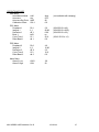
TABLE OF CONTENTS
SECTION
PAGES
INTRODUCTION ............................................................... 3
INSTALLATION................................................................. 4
OPERATION ................................................................... 10
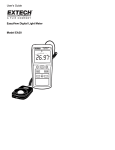
Light meter ......................................................................... 10
Light meter example ........................................................... 14
Temperature & Humidity controllers ................................... 15
Over temperature safety ..................................................... 16
Computer communications ................................................. 16
Humidity control calibration ................................................ 16
Chart recorder .................................................................... 17
Condensate recirulating system ......................................... 17
Motorized turn table ........................................................... 18
MAINTENANCE ....................................................................... 19
Replacement parts ............................................................. 20
APPENDIX ................................................................................ 21
Terminology........................................................................ 21
Example.............................................................................. 22
Controller default settings .................................................. 24
Chart recorder default settings ........................................... 28
6500 SERIES USER MANUAL Rev D
3/22/2013
2
INTRODUCTION
CARON’s 6500 series photostability chambers are designed specifically to meet ICH and FDA
requirements for photostability testing. Near UV and visible light testing is performed
simultaneously using D65 lamps according to ICH Q1B option 1.
Calibrated photon detectors measure relevant lamp intensity on the product shelf. Lamp intensity
(W/m2 or Lux) and exposure level (W-hr/m2 or Lux-hr) are conveniently displayed at eye-level by a
calibrated digital light meter. After a programmed exposure level is reached the lamps
automatically shut-off. To enhance reliability, temperature and humidity (optional) conditions are
monitored and controlled throughout the photostability test.
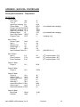
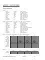
SPECIFICATIONS
Lamp type
UV intensities, typical
VIS intensities, typical
Temperature Range
Temperature Control
Features
Relative humidity range
Humidity control
Shelves, # of
Light meter, # of
UVA light detector, # of
VIS light detector, # of
Electrical power (60Hz)
Shipping weight, lbs
Options / Accessories
Circular chart recorders
Records:
Fluorescent, D65
1.5 W/m2 (requires about 133 hours to achieve ICH recommendation of
200W-hr/m2)
10 klux (requires about 120 hours to achieve ICH recommendation of
1.2 million lux-hr)
15 – 40°C
± 0.3°C
6510
1
1
1
115V 20A
475
6515
*30 – 75%
± 5%
1
1
1
1
115V 20A
475
6530
2
2
2
115V 25A
900
6535
*30 – 75%
± 5%
2
2
2
1
115V 25A
900
REC-202
Temperature
Light meter
REC-203
Temperature
Humidity
Light meter
REC-203
Temperature
Light meter 1
Light meter 2
REC-204
Temperature
Humidity
Light meter 1
Light meter 2
UVA light detector
VIS light detector
LGT-202
LGT-203
* Humidity range limited by 5°C minimum dewpoint
Light intensity will vary based on model number, lamp age, chamber temperature, shelf height and shelf location. Models 6510 and 6515 will
have lower intensities than models 6530 and 6535.
Chamber ambient conditions 20°C to 25°C. Exceeding 25°C can result in chamber failure.
6500 SERIES USER MANUAL Rev D
3/22/2013
3
INSTALLATION
Unpacking
This product has been completely tested, cleaned and packed for shipment. Carefully remove all
packing material. Please examine the chamber completely. Should any damage be found, notify
the delivering carrier immediately.
Report any shortages to Customer Service at 1-740-373-6809.
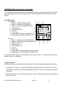
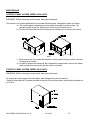
Chamber Location
Chamber ambient conditions 20°C to 25°C. Exceeding 25°C can result in chamber failure.
The chamber must be located in a dry, clean, and level area. Allow a 4” clearance from the back
and top of the chamber for proper air circulation and ease of installation. Locate the chamber in
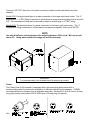
an area out of direct sunlight and away from heating and cooling ducts. The figure below shows a
side view of the chamber with air vent and access port locations.
6500 SERIES USER MANUAL Rev D
3/22/2013
4
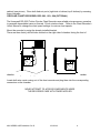
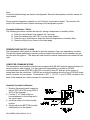
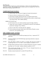
Light control boxes (6530 & 6535 only)
Mount the two light control boxes on the left side of the
chamber. Mount the light control box with the longer cord on
top. (See picture to right.) Connect the boxes to the chamber
using the mounting screws already screwed into the chamber.
Tighten the screws so that the boxes are held securely.
Connect the upper box’s line cord into the receptacle mounted
on the side of the chamber. Connect the lower box’s line cord
into the receptacle on the upper light control box.
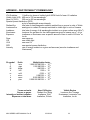
Drain connection (6515 & 6535 only)
Connect a 3/8” NPT drain line to the drain connection located on the lower
back side of the chamber. The figure below shows the drain connection on
the back of the chamber. For proper operation the drain hose should not
be kinked or bent. It should run down from the chamber and go into an
open floor drain.
Water supply (6515 & 6535 only)
6500 SERIES USER MANUAL Rev D
3/22/2013
5
Connect a 3/8” NPT drain line to the drain connection located on the lower back side of the
chamber.
Model 6535: Facing the back there is a water connection in the upper right hand corner. The ¼”
compression – ¼” MPT fitting is attached to a filter/strainer and pressure regulator that is set at 40
PSI. The compression fitting can be removed to adapt to another type of ¼” MPT fitting.
Model 6515: The back side there is a water connection in the lower right hand corner. The ¼”
compression fitting is attached to a filter/strainer and pressure regulator that is set at 40 PSI.
NOTE
Use only distilled or deionized water with resistivity between 50kΩ-cm & 1 MΩ-cm and pH
above 6.5. Using water outside this range will void the warranty.
WARNING!
For personal safety, this chamber must be properly grounded.
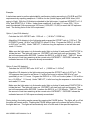
Power
The Power Cord of this chamber is equipped with a grounded plug which mates with a
corresponding outlet to minimize the possibility of electrical shock from the chamber. CARON
recommends that the chamber have a dedicated wall outlet. Models 6510 & 6515 have a 20 amp
plug (right picture) and models 6530 & 6535 have a 30 amp plug (left picture).
6500 SERIES USER MANUAL Rev D
3/22/2013
6
Install Lamps
Install the fluorescent lamps above each shelf. Insert bi-pin (longer) lamps into the lamp holders
and rotate a ¼ turn. Mount the high output (shorter) lamps by pressing the one end into the
plunger and then into the fixed end. If one lamp in not installed properly or burned out, it will
affect the performance of other lamps.
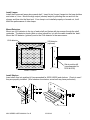
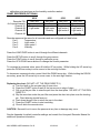
Mount Detectors
Mount one UVA detector to the top of each shelf and fasten with two screws though the shelf
underside. The detector lends (white or clear) should be ‘up’ with the cable towards the ‘back’.
Mount the VIS detector (optional) next to the UVA detector in the same manor.
UVA detector
VIS detector
(optional)
3
4
5
Set at position #4
(recommended for
6530 & 6535)
SHELF FRONT
Install Shelves
Insert shelf clips into position #4 (recommended for 6535 & 6535) and shelves. Check to see if
they are properly installed. (Wire shelves show below, actual unit may have perforated)
6500 SERIES USER MANUAL Rev D
3/22/2013
7
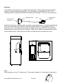
Detectors
A UVA detector (pictured below) is supplied with each shelf. Some models also come with VIS
detectors or can be purchased separately. The UVA detector is identified with “TD” & “UVA”
markings and has a white lens while the VIS detector has markings “Y” and “W” with a clear lens.
Calibration Info
Lens
Identification
location
Plug this end
into meter
Attach the detector(s) to the shelf with two screws so the lends faces up. Route the cable through
the 3” port on the back (6510 & 6515) or right side (6530 & 6535). Plug the detector into the
meter as shown. For models with more than one shelf, plug the upper shelf into the upper light
meter box and the lower shelf into the lower box. When in use, remove the black dust cover from
over the detector lens. Since the lens is fragile, re-install the dust cover when not in use.
Port
Install foam plug to cover 3” detector port. Place rubber stopper in 2” access port on right side of
6500 SERIES USER MANUAL Rev D
3/22/2013
8
cabinet (see picture). Close both fresh air ports (right side of cabinet, top & bottom) by screwing
them clockwise.
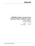
CIRCULAR CHART RECORDER, REC-202, -203, -204 (OPTIONAL)
The Honeywell DR 4500 Truline Circular Chart Recorder uses reliable microprocessor operation
to generate dependable traces on thermal 12-inch circular charts. Refer to the Chart Recorder’s
User’s Manual to change the chart speed settings for various chart speeds.
Mount the recorder by using the already installed bracket.
There are three factory drilled holes located on the right side of chamber facing the front of
chamber. Using the factory supplied screws, screw the recorder to the side of the chamber.
Locate both wire cords coming out of the chart recorder and plug them into the corresponding
connectors on the chamber
NEVER ATTEMPT TO ACCESS COMPONENTS INSIDE
THE RECORDER CASE WITH POWER APPLIED.
6500 SERIES USER MANUAL Rev D
3/22/2013
9
OPERATION
Light Control
Each light bank (shelf) is individually controlled in either manual or automatic mode. In manual
mode, the MAN ON/OFF button turns the lights on & off. In automatic mode, the lights turn on
when an exposure is started and off automatically at the end (START/STOP button). Press
MAN/AUTO to toggle between the two modes.
The light meter buttons and screen features of the are illustrated below.
Units
Value
(both manual &
automatic modes)
6500 SERIES USER MANUAL Rev D
3/22/2013
10
Light Meter Modes
There are five different light meter modes. The current light meter mode flashes in the status
portion of the display (lower right side).
READY
View intensity & other variables and ready to start an exposure or test
EXPOSE
Exposure or test is running
PAUSE
Exposure or test is paused
COMPLT
Exposure or testing is complete
Program
Exposure level maybe programmed and calibration parameters read
READY Mode
In the READY mode, the following functions can be done:
1. View variables (press the SCROLL button)
INTENSITY
measured light intensity for connected light detector. If the UVA detector is
plugged in, it will display the UVA intensity in units of W/m2. If the VIS
detector is plugged in, it will display the VIS intensity in units of lux.
TIME LFT
length of time a test would take given the current INTENSITY and EXP LVL
INTNSTY2
estimated light intensity for the detector not currently plugged in. If a UVA
detector is plugged in, then this displays the estimated VIS intensity in units
of lux. If the VIS detector is plugged in, then this displays the estimated
UVA intensity in units of W/m2. These values are only estimated and should
be verified by the appropriate detector!
EXPLVL
current exposure level displayed in units corresponding to current detector
2. Start exposure or test (press the START/STOP button)
EXPOSE Mode
Expose or test mode is intended to keep the lights on for a specified exposure level and then
automatically shut them off. This only works if the light meter is in the automatic mode, not
manual! To enter the EXPOSE mode, press the START/STOP button in the READY mode.
In the EXPOSE mode, the following functions can be done:
1. View variables (press the SCROLL button)
INTENSITY
measured light intensity for connected light detector in W/m2 or lux.
EXPOSE 1
total light exposure for connected light detector in W-hr/m2 or lux-hr
accumulated since starting the exposure or test.
TIME LFT
length of time remaining until exposure or test is complete
6500 SERIES USER MANUAL Rev D
3/22/2013
11
INTNSTY2
estimated light intensity for the detector not currently plugged in (lux or W/
m2). These values are estimated and are provided only as a guideline!
EXPOSE 2
estimated total light exposure for detector not currently plugged in (lux-hr or
W-hr/m2) accumulated since starting the exposure or test.
EXPLVL
current exposure level displayed in units corresponding to current detector
2. Stop exposure or test (press the START/STOP button)
3. Pause current exposure or test (press the PAUSE button). This turns off the lights. However,
the meter still monitors intensity and exposure levels.
PAUSE Mode
Pressing the PAUSE button during an exposure or test turns off the lights. Pressing the PAUSE
button again turns the lights back on and resumes the exposure or test. While the lights are off,
the meter still functions by measuring light intensity and computing the exposure level.
COMPLT
After an exposure or test is complete, COMPLT will flash in the status section of the display. The
lights will have automatically shut off. Press the START/STOP button to return to the READY
mode.
PROGRAM Mode
PROGRAM mode is used to change the exposure level (EXPLVL) and set the VIS to UVA ratio or
OFFSET. It can also be used to view calibration information about the light detector. In program
mode, the buttons take on different features as identified by the red characters underneath the
button. Enter the PROGRAM mode by pressing the RESET button immediately followed by the
PROG button. Press the red SCROLL button again to view the first variable.
Scroll through the variables by pressing the SCROLL (red) button.
EXPLVL
displays current exposure level in exponential notation and units
consistent with attached detector. The cursor flashes at the current digit.
The ù button increments the digit. Use the ÷ button to move to the next
digit. Once the desired value is displayed, press the ENTER button. To
abort the entry, press the EXIT button (also exits PROGRAM mode).
Factory default EXPLVL is 2.00 e+2 for the UVA detectors and 1.20e+6 for
the VIS detectors.
SERIAL NUMBER
shows the serial number of the attached detector (protected).
UNITS SELECT
shows the units (intensity) for the attached detector (protected). The UVA
detector will display W/m2 while the VIS detector will display lux. The
upper left corner displays the instantaneous intensity reading. A “dn” or
“UP” displayed in the lower right corner is for factory purposes only.
6500 SERIES USER MANUAL Rev D
3/22/2013
12
FACTOR
displays factory calibration factor of attached detector (protected). The
upper left corner displays the instantaneous intensity reading.
CALIBRATION DATE shows the day, month and year the attached detector was last calibrated
(protected).
OFFSET
displays the estimated ratio of the UVA to VIS detectors (protected). See
offset calibration below for more details.
OFFSET (VIS to UVA ratio)
Since only one detector maybe connected to the meter at a time, only UVA or VIS can be
measured without physically changing detectors. However, there maybe situations where it would
be beneficial to know what the other detector would read if it were attached. This can be done
using the OFFSET feature.
For a specific geometric location (position on shelf and shelf height) and lamp age, there is a
given VIS & UVA ratio. This ratio can be entered into the light meter and both VIS & UVA
readings will be displayed without disconnecting the detector.
WARNING:
Moving the detector in any way will affect this ratio. It is
imperative that it be check & interpreted properly.
Detector OFFSET values as supplied from the factory are 1.739e-4 for UVA and 5.751e+3 for VIS.
The table below suggests typical detector OFFSET values for each shelf height with the detectors
properly mounted.
Shelf
6530 & 6535
Position
UVA
VIS
1
2.040 e-4
4.903 e+3
2
1.813 e-4
5.517 e+3
3
1.848 e-4
5.412 e+3
*4
1.739 e-4
5.751 e+3
5
1.669 e-4
5.993 e+3
6
1.660 e-4
6.023 e+3
* Factory default values
Procedure for using the UVA detector to display accurate VIS readings:
1. Plug the UVA detector in and locate it as desired
2. Record the INTENSITY reading (ex: 2.25 W/m2)
3. Plug the VIS detector in and locate it exactly where the UVA detector was located!!
4. Record the INTENSITY reading (ex: 12,000 lux)
5. Calculate the UVA / VIS ratio (ex: 1.875e-4 = 2.25 W/m2 / 12,000 lux)
6500 SERIES USER MANUAL Rev D
3/22/2013
13
6. Enter PROGRAM mode (press RESET + PROG)
7. Press the SCROLL button until SERIAL NUMBER is displayed
8. WARNING: Screens displayed beyond this point are locked to prevent accidental changing of
detector calibration information. To unlock the screens, push the ù button until the left digit
displays 4. Then press the ENTER button. Push the ù button until the display shows 8 and
press the ENTER button a second time. This action will unlock all screens. Accidental
changing of the calibration information can be re-entered from the calibration certificate
provided with the detector.
9. Press the SCROLL button until OFFSET is displayed
10. Use the ù & ÷ buttons to enter the UVA / VIS ratio (ex: 1.875e-4)
11. Store the value by pressing the ENTER button
12. Exit PROGRAM mode by pressing EXIT
Now for the detector location, INTNSTY2 and EXPOSE2 will display VIS values even when the
UVA detector is attached. To use the VIS detector to display UVA readings, repeat the above
steps switching the two detectors and inverting the ratio (ie. OFFSET = VIS / UVA).
EXAMPLE – PROGRAMING AN EXPOSURE LEVEL
The following example shows how to program a UVA exposure level of 200 W-Hr/m2 into the light
meter.
1.
Plug the UVA detector into the light meter
2.
Press the RESET button; “READY” should flash in the status display area
3.
Press the RESET button immediately followed by the PROG button; the screen should
display “PROGRAM MODE, PRESS RESET TO EXIT”
4.
Press the (red) SCROLL button; “EXPLVL” with a number and units will appear
5.
Press the ù button (increment digits) and the ÷ button (move between digits) to change
the value to 2.000e+02 (or 200 W-hr/m2).
6.
Press the ENTER button; screen changes to display “SERIAL NUMBER”
7.
Press the EXIT button to return back to “READY” mode; “INTENSITY” will be displayed
8.
Verify the programming was correct by pressing the (black) SCROLL button 3 times and
“EXPLVL” appears.
9.
The value listed should be 2.000e+02 W-hr/m2
6500 SERIES USER MANUAL Rev D
3/22/2013
14
CONTROLLERS: Temperature & Humidity
For CARON Model 6030 Environmental Test Chambers that are equipped with Watlow 96 single
point and ramping controllers, use appendix B for operating instructions and default controller
settings.
Controller Layout
1
Temperature
1 - Output 1, indicates heating system
2 - Output 2, indicates cooling system
3 - Output 3, indicates temperature alarm
4 - “Advance” key
9
5 - “Infinity/Home” key
6 - “Up” key
8
7 - “Down” key
8 - Lower display, Setpoint Temperature (°C)
9 - Upper display, Actual Temperature (°C)
2
3
2 0 .0
2 0 .0
Humidity
1 - Output 1, indicates system humidification
2 - Output 2, indicates system dehumidification
3 - Output 3, Not used
4
4 - “Advance” key
5 - “Infinity/Home” key
6 - “Up” key
7 - “Down” key
8 - Lower display, Setpoint Relative Humidity (%RH)
9 - Upper display, Actual Relative Humidity (%RH)
6
5
7
The Output indicator lights on the controller are not continuously on. They are only on when the
specific system is in operation.
Change Set Point
Use the up and down arrow push-buttons to obtain the desired setpoint temperature or humidity.
1. When power is turned on, an alarm will briefly sound and reset after a few seconds. Set the
temperature controller to the desired temperature set point. Use the up & down arrow keys as
necessary.
2. (6515 & 6535 only) Turn on the humidity switch. Set the humidity controller to the desired set
point like in step 1.
6500 SERIES USER MANUAL Rev D
3/22/2013
15
Note:
Controller default settings are listed in the Appendix. See also the separate controller manual for
more details.
During normal refrigeration operation, a soft “clicking” sound can be heard. This sound is the
result of the solenoid control valves switching in the refrigeration system.
Controller Calibration / Offset
The following procedure outlines the steps for setting a temperature or humidity offset.
A. Press the up and down keys together for 3 seconds
B. Press the advance key until CAL1 is in the lower display
C. Press the up or down keys to obtain the desired temperature or humidity offset
D. Press the Infinity key to return to the home page
TEMPERATURE SAFETY ALARM
The temperature safety alarm is intended to alert the operator of an over-temperature condition.
This would indicate inadequate internal cooling and should be rectified, as the chamber can get
very hot with the lights on. This alarm will reset once the internal temperature has reached a safe
level
COMPUTER COMMUNICATIONS
The temperature and humidity controllers are equipped with RS-485 computer communications for
remote control or data logging. It is the customer’s responsibility to provide an RS-485
communications board or RS-485 to RS-232 converter for their PC and set up the system to
accept data from the controllers. CARON can provide information about the type of RS-485 board
and/or converter for your system. Terminations 11(R/T -), 12 (R/T +) and 13 (GND) located on the
back of the chamber are used to connect for communications.
Humidity Controller Calibration
1. Remove the access panel located on
the left (6510 & 6515) or top (6530 &
6535) of the chamber.
2. Find the 2” x 3” black utility box
located adjacent to the wiring and in
the service area.
3. Inside the utility box is the humidity
module.
4. Slowly adjust the BOTTOM humidity
calibration pot to the desired
6500 SERIES USER MANUAL Rev D
3/22/2013
16
calibration point as shown on the humidity controller readout.
CHART RECORDER (OPTIONAL)
Recorder P/N
# of inputs/channels
Channel #1
Channel #2
Channel #3
Channel #4
6510
REC-202
2
Temperature
Light meter
6515
REC-203
3
Temperature
Light meter
Humidity
6530
REC-203
3
Temperature
Light meter 1
Light meter 2
6535
REC-204
4
Temperature
Light meter 1
Light meter 2
Humidity
Recorder pens are the same for all recorders and are configured as listed below
Pen 1
Temperature
Pen 2
Light meter 1
Pen 3
Light meter 2
Pen 4
Humidity
Press the LOWR DISP button to scroll through the different channels.
Press the SETUP button to scroll through the group menus.
Press the FUNC button to scroll through a particular group.
Press the UP & DOWN arrow buttons to change the current parameter
To increment a numerical value, press & hold the UP arrow key. While holding the UP arrow key,
press the DOWN arrow key to move cursor to the next digit location.
To decrement a numerical value, press & hold the DOWN arrow key. While holding the DOWN
arrow key, press the UP arrow key to move cursor to the next digit location.
Replacing the chart: (DO NOT LIFT THE PENS DIRECTLY)
a) Turn the latch on the recorder door & open door
b) Press the CHART button & wait till the pen moves to edge of chart.
c) Pull up on the pen lifter to raise the pen from the chart plate. DO NOT LIFT THE PEN
DIRECTLY.
d) Slip the new chart under the pen lifter and press the chart into place over the locating
pin. Chart lettering should face you.
e) Push down the pen lifter to return the pen to the chart.
f) Press the CHART button to start recording
g) Close & latch the recorder door.
CAUTION: Be careful not to move the pen arm at any time or damage may occur.
See the Appendix for default controller settings and consult the Honeywell Recorder Manual for
additional operation information.
6500 SERIES USER MANUAL Rev D
3/22/2013
17
CONDENSATE RECIRCULATING SYSTEM; CRS-101 (ACCESSORY)
The Condensate Recirculating System is used in conjunction with CARON’s Series 6000 Test
Chambers, as a water delivery system. This system is typically used in facilities where a floor
drain or in-house source of distilled or deionized water are not available. The system provides
continuous, clean, filtered water to the chamber’s humidity injection system, collects and recycles
the condensate that forms in the base of the chamber.
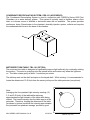
MOTORIZED TURN-TABLE; TBL-101 (OPTION)
The motorized turn-table is designed to significantly improve light uniformity by continually rotating
the product. The motor’s cord plugs into the internal outlet and rotates only when the lights are
on. The table rotates gently at about 1 revolution per minute.
The tabletop rests on the shelf and spins on the keyed shaft. While running, it is recommended to
locate the detectors at 10 O’clock from the center just beyond the table perimeter (see picture).
Note:
Averaging the four quadrant light intensity readings (12,
3, 6 and 9 O’clock) of the table while stationary
approximates the light intensity of the table while being
rotated. The lowest intensity over the table area is at the
perimeter. Therefore, locating the detectors off the table
(as shown in picture) such that the intensity approximates
the ‘perimeter four quadrant average’ provides a good
6500 SERIES USER MANUAL Rev D
3/22/2013
18
FRONT (top view)
measure of the lowest light exposure on the rotating table surface.
6500 SERIES USER MANUAL Rev D
3/22/2013
19
MAINTENANCE
CONTROL PANEL ACCESS MODEL 6530 & 6535
WARNING: Before removing control panel, disconnect all power!
The access to all control panel and top mounted electrical parts, refrigeration parts as follows:
a) The control panel components can be easily accessed by removing the (6)
screws located at the top, and bottom of the control housing cover.
b) Pull the front mounted control housing cover towards you to access the control
panel.
c) Next remove the (4) screws that hold the control panel housing in place, and the
housing will be loose.
d) In order to access the electrical and refrigeration components, remove the sheet
metal screws that are holding the top cover in position.
CONTROL PANEL ACCESS MODEL 6510 & 6515
WARNING: Before removing control panel, disconnect all power!
To access all control panel, electrical parts, and refrigeration parts this can be
Done by removing the (2) screws located at the top of the service panel, and pulling the panel out
of it’s slot.
6500 SERIES USER MANUAL Rev D
3/22/2013
20
Chart Recorder
The recorder does not require any periodic maintenance. However, the chart will have to be
replaced as required. The chart paper can be ordered directly from Honeywell PH# 1-800-4239883 (USA & CANADA) PN# 30755317-001.
CHAMBER MAINTENANCE SCHEDULE
a) Replace lamps after 5000 hours of usage (not covered under warranty)
b) Vacuum or blow out condensing unit fins. (Monthly)
c) Clean interior chamber stainless steel with a non abrasive glass cleaner.
d) Check air filter (Model 6510 & 6515), replacement filters can be ordered through
Caron Service Dept. 740-373-6809. (Monthly)
MODELS 6515 & 6535 only
e) Check drains in floor, rear cabinet and drip trough for blockage. (Monthly)
f) Using a level, check to maintain ½ of a bubble tilt to the back of the chamber for
proper water drainage. (Every 6 Months)
g) Clean out water filter for humidity water inlet. (Monthly)
h) Check condensate drip pan located inside of 6010 (Every 3 Months), remove
service door, lower right hand corner
REPLACEMENT PARTS / OPTIONS
LGT-111
Fluorescent D65 24 inch F20T12/65 bi-pin lamps (set of four). Lamps are 23.75”
end to end.
LGT-124
Fluorescent D65 24 inch F24T12/D/HO high output lamp (individual) Lamps are
21.75” end to end.
LGT-202
UVA light detector detects the amount of incident UVA light and connects to
chamber light meter via a 7 foot cable. Includes calibration traceable to N.I.S.T.
LGT-203
VIS light detector detects the amount of incident VIS light and connects to chamber
light meter via a 7 foot cable. Includes calibration traceable to N.I.S.T.
PPR-201
Chart recorder paper (thermal), 12” circular, 100 count, Honeywell brand (for use
with REC-202, REC-203 & REC-204)
SHV-108
Stainless steel perforated shelf for models 6530 and 6535 only
6500 SERIES USER MANUAL Rev D
3/22/2013
21
SHV-109
Stainless steel perforated shelf for models 6510 and 6515 only
6500 SERIES USER MANUAL Rev D
3/22/2013
22
APPENDIX – PHOTOSTABILITY TERMINOLOGY
ICH Guideline
1.2million lux hours of visible light & 200W-hr/m2 of near UV radiation
Visible Light (VIS) 400 nm to 700 nm wavelength
Near UV (UVA)
320 nm to 400 nm wavelength
Spectral power distribution (SPD)
a plot of wavelength verses intensity
Radiant flux
total rate of electromagnetic radiation emitted from a source in units of Watts
Luminous flux
analogous to radiant flux except restricted to visible light in units of Lumens
Irradiance
total rate of energy of all wavelengths incident on a given surface area (W/m2)
Illuminance
luminous flux per area for the visible spectrum given in lumens per m2, or lux
Exposure
irradiance or illuminance over a specific amount of time in units of W-hr/m2 or
lux-hr
Dose
see exposure
VIS
see visible light
UVA
see near UV
SPD
see spectral power distribution
Intensity
rate of energy incident on a given surface area (see also irradiance and
illuminance)
SI symbol
T
G
M
k
m
µ
n
p
Prefix
tera
giga
mega
kilo
milli
micro
nano
pico
Multiplication factor
1 000 000 000 000 = 10+12
1 000 000 000 = 10+9
1 000 000 = 10+6
+3
1 000 = 10
-3
0.001 = 10
0.000 001 = 10-6
-9
0.000 000 001 = 10
-12
0.000 000 000 001 = 10
Terms and units
Source or power
Intensity or incident radiation
Exposure or total dose
6500 SERIES USER MANUAL Rev D
Near UV Region
Radiant flux, Watts
Irradiance, W/m2
Irradiation, W-hr/m2
3/22/2013
Visible Region
Luminous flux, Lumens
Illuminance, Lumens/m2=lux
Irradiation, lux-hr
23
Example:
A technician wants to perform photostability confirmatory testing according to ICH Q1B and FDA
requirements by exposing samples to 1.2million lux-hrs (visible region) and 200W-hr/m2 (UVA
region) of light. With the UVA detector attached to the light meter, it reads an INTENSITY of 1.8
W/m2 and INTNSTY2 of 12 Klux. Under these conditions, it will take 111 hours (200 / 1.8) to
reach the desired UVA exposure and 100 hours (1,200,000 / 12,000) to reach the VIS exposure
level. The limiting factor is the UVA requirement.
Option 1 (use UVA detector)
Calculate the UVA OFFSET ratio: 1.500 e-4 = (1.8 W/m2 / 12000 lux)
Attach the UVA detector to the light meter and program the OFFSET ratio to 1.500 e-4. The
INTENSITY reads 1.8 W/m2 and INTNSTY2 shows 12 Klux. Program the EXPLVL to 2.000
e+2 W-hr/m2 (or 200). Under TIME LFT, it tells how long the exposure or test will take and
reads 111 hours.
Make sure the light meter is in Automatic mode (light on button lit) and press START/STOP to
initiate the test. The lights will come on. EXPOSE 1 will start from zero and increase. The
test will commence when EXPOSE 1 reaches the EXPLVL or 200 W-hr/m2. TIME LFT shows
the amount of test time remaining at the current rate of INTENSITY. EXPOSE 2 shows the
estimated amount of VIS exposure already accumulated.
Option 2 (use VIS detector)
Calculate the VIS OFFSET ratio: 6.667 e+3 = (12000 lux / 1.8 W/m2)
Attach the VIS detector to the light meter and program the OFFSET ratio to 6.667 e+3. The
VIS exposure level must be set above 1.2 million lux-hours to achieve 200 W-hr/m2 and
specifically to run 111 hours. Program the EXPLVL to 1.332 e+6 lux-hrs (where 1.332 e+6 luxhrs = 12,000lux * 111 hours). Under TIME LFT, it tells how long the exposure or test will take
and reads 111 hours.
Make sure the light meter is in Automatic mode (light on button lit) and press START/STOP to
initiate the test. The lights will come on. EXPOSE 1 will start from zero and increase. The
test will commence when EXPOSE 1 reaches the EXPLVL or 1.332 Mlux-hr. TIME LFT shows
the amount of test time remaining at the current rate of INTENSITY. EXPOSE 2 shows the
estimated amount of UVS exposure already accumulated.
During testing, the testing maybe paused by pressing the PAUSE button. The lights will go off but
the meter will remain active. Pressing the PAUSE button again will continue the test by turning
the lights back on. The lights will automatically shut-off at the end of the specified exposure.
6500 SERIES USER MANUAL Rev D
3/22/2013
24
EXAMPLE – PROGRAMING AN EXPOSURE LEVEL
The following example shows how to program a UVA exposure level of 200 W-Hr/m2 into the light
meter.
1. PIug the UVA detector into the light meter.
2. Press the RESET button; “READY“ should flash in the status display area.
3. Press the RESET button immediately followed by the PROG button; the screen should display
“PROGRAM MODE, PRESS RESET TO EXIT“
4. Press the (red) SCROLL button; “EXPLVL“ with a number and units will appear.
5. Press the > button (increment digits) and the < button (move between digits) to change the
value to 2.000e+02 (or 200 W-hr/m2).
6. Press the ENTER button; screen changes to display “SERIAL NUMBER“.
7. Press the EXIT button to return back to “READY“ mode; “INTENSITY“ will be displayed.
8. Verify the programming was correct by pressing the (black) SCROLL button 3 times and
“EXPVL“ appears.
The value Iisted shouid be 200 W-hr/m2
The following example shows how to program a VIS exposure level of 1.2 Mlux-hr into the light
meter.
1. PIug the VIS detector into the light meter.
2. Press the RESET button; “READY“ should flash in the status display area.
3. Press the RESET button immediately followed by the PROG button; the screen should display
“PROGRAM MODE, PRESS RESET TO EXIT“
4. Press the (red) SCROLL button; “EXPLVL“ with a number and units will appear.
5. Press the > button (increment digits) and the < button (move between digits) to change the
value to 1.200e+06 (or 1,200,000 lux-h).
6. Press the ENTER button; screen changes to display “SERIAL NUMBER“.
7. Press the EXIT button to return back to “READY“ mode; “INTENSITY“ will be displayed.
8. Verify the programming was correct by pressing the (black) SCROLL button 3 times and
“EXPVL“ appears.
The value Iisted shouid be 1.200 Mlux-hr
6500 SERIES USER MANUAL Rev D
3/22/2013
25
APPENDIX - WATLOW CONTROLLER
Factory Set Parameters – Temperature
SETUP PAGE
Global Menu
Units Type
Unit
°C or °F
C-F
Input Error Latching Err
Failure Mode
FAiL
Power Limit Set Point PLSP
High Pwr Lmt Above PL A
High Pwr Lmt Below PL b
Ramping Mode
rP
Open Loop Detect
OPLP
Program Type
PtYP
SI
°C
nLAt
bPLS
800
100.0
100.0
OFF
off
ti
(ramping only)
Input 1 Menu
Sensor Type 1
Sen1
Input 1
In 1
Range Low 1
rL 1
Range High 1
rh 1
Decimal 1
dEC1
Input Software Filter1 Ftr1
rtd
din
5.0
60
0.0
-15.0
(6510/6515 is 1)
Input 2 Menu
Input 2
Event Function
Event Condition
In 2
E Fn
E cn
off
nonE
Output 1 Menu
Output 1
Ot 1
hEAt
Output 2 Menu
Output 2
Ot 2
COOL
Output 3 Menu
Output 3
Ot 3
Alarm 3 Type
AtY3
Alarm Hysteresis 3 AhY3
Latching 3
Lat3
Silencing 3
SiL3
Alarm Active Sides 3 Sid3
Alarm Logic 3
Lgc3
Alarm Annunciation 3 Anu3
AL
dE
0.1
no
no
bOth
AL O
no
Output 4 Menu
Baud Rate
Address
19.20
1
bAUd
Addr
6500 SERIES USER MANUAL Rev D
(not available with ramping)
(not available with ramping)
{2nd set point option: E In}
{2nd set point option: SP}
{2nd set point option: E In}
3/22/2013
26
OPERATIONS PAGE
User Menu
Auto-Manual Mode
Auto-tune
Auto-tune Set Point
Calibration Offset
A-M
Aut
AtSP
CAL 1
Auto
OFF
90
0.0
(not available with ramping)
PID1 Menu
Propband 1
Integral 1
Derivative 1
Burst 1
Cycle Time 1
Dead Band 1
Pb 1
It 1
dE 1
brS1
Ct 1
db 1
5.0
99.99
0.00
no
50.0
0.0
(6510/6515 is 4.6)
(6510/6515 is 9.50)
(6510/6515 is 2.3)
PID2 Menu
Propband 2
Integral 2
Derivative 2
Cycle Time 2
Dead Band 2
Pb 2
It 2
dE 2
Ct 2
db 2
4.6
10.00
2.3
10.0
0.0
Alarm Menu
Alarm 3 Low
Alarm 3 High
A3LO
A3hi
-50
50
6500 SERIES USER MANUAL Rev D
(6510/ 6515 is 1.0)
3/22/2013
27
Factory Set Parameters – Humidity
SETUP PAGE
Global Menu
Units Type
Unit
Input Error Latching Err
Failure Mode
FAiL
Power Limit Set Point PLSP
High Pwr Lmt Above PL A
High Pwr Lmt Below PL b
Ramping Mode
rP
Open Loop Detect
OPLP
Program Type
PtYP
Input 1 Menu
Sensor Type 1
Sen1
Input 1
In 1
Range Low 1
rL 1
Range High 1
rh 1
Decimal 1
dEC1
Input Software Filter1 Ftr1
SI
nLAt
bPLS
50
100.0
100.0
OFF
off
ti
In 2
E Fn
E cn
off
nonE
Output 1 Menu
Output 1
Ot 1
hEAt
Output 2 Menu
Output 2
Ot 2
COOL
Output 3 Menu
Output 3
Ot 3
Alarm 3 Type
AtY3
Alarm Hysteresis 3 AhY3
Latching 3
Lat3
Silencing 3
SiL3
Alarm Active Sides 3 Sid3
Alarm Logic 3
Lgc3
Alarm Annunciation 3 Anu3
AL
dE
1
no
no
bOth
AL O
no
Output 4 Menu
Baud Rate
Address
19.20
2
6500 SERIES USER MANUAL Rev D
(not available with ramping)
(ramping only)
Proc
0- 5
0
100
0
2.0
Input 2 Menu
Input 2
Event Function
Event Condition
bAUd
Addr
(not available with ramping)
{2nd set point option: E In}
{2nd set point option: SP}
{2nd set point option: LO}
3/22/2013
28
OPERATIONS PAGE
User Menu
Auto-Manual Mode
Auto-tune
Auto-tune Set Point
Calibration Offset
A-M
Aut
AtSP
CAL 1
Auto
OFF
90
0
PID1 Menu
Propband 1
Integral 1
Derivative 1
Burst 1
Cycle Time 1
Dead Band 1
Pb 1
It 1
dE 1
brS1
Ct 1
db 1
2
0.00
0.00
no
4.0
0
PID2 Menu
Propband 2
Integral 2
Derivative 2
Cycle Time 2
Dead Band 2
Pb 2
It 2
dE 2
Ct 2
db 2
6
0.00
0.02
7.0
0
Alarm Menu
Dead Band 2
Alarm 3 Low
Alarm 3 High
db 2
A3LO
A3hi
0
-5
5
6500 SERIES USER MANUAL Rev D
(not available with ramping)
3/22/2013
29
APPENDIX – CHART RECORDER
Factory set parameters
INPUT 1
INPUT 1
DECIMAL
UNITS
IN1 TYPE
IN1 HI
IN1 LO
BIAS 1
FILTER 1
BURNOUT
ENABLE
XXX.X
DEG C
100PT
482.2
-184.4
0.0
0
UP
Input 1 actuation
Decimal point location
Temperature Units
Input 1 actuation type
Input 1 high range value
Input 1 low range value
Input 1 bias or offset
Input 1 filter
Burnout protection
INPUT 2 (UVA note: 0W/m2 = 0Vdc; 1W/m2 = 1Vdc = 20%; 2.55Vdc is maximum)
INPUT 2
ENABLE
Input 2 actuation
DECIMAL
XXXX
Decimal point location
UNITS
XXXXX
Temperature units
ENGUNITS
PERCT
Engineering units
IN2 TYPE
0-5V
Input 2 actuation type
XMITTER2
LINEAR
Input 2 transmitter characterization
IN2 HI
100
Input 2 high range value
IN2 LO
0
Input 2 low range value
BIAS 2
0
Input 2 bias or offset
FILTER 2
0
Input 2 filter
BURNOUT
UP
Burnout protection
INPUT 3 (VIS note: 0klux = 0Vdc; 10klux = 1Vdc = 20%; 2.55Vdc is maximum)
6510
6515
6530
DISABL
ENABLE
ENABLE
INPUT 3
DECIMAL
XXXX
XXXX
UNITS
XXXXX
XXXXX
ENGUNITS
PERCT
PERCT
IN3 TYPE
0-5V
0-5V
XMITTER3
LINEAR
LINEAR
IN3 HI
100
100
IN3 LO
0
0
BIAS 3
0
0
FILTER 3
0
0
BURNOUT
UP
UP
6535
ENABLE
XXXX
XXXXX
PERCT
0-5V
LINEAR
100
0
0
0
UP
INPUT 4
INPUT 4
DECIMAL
6510
DISABL
6500 SERIES USER MANUAL Rev D
6515
DISABL
6530
DISABL
3/22/2013
6535
ENABLE
XXXX
30
XXXXX
PERCT
0-5V
LINEAR
100
0
0.0
0
UP
UNITS
ENGUNITS
IN4 TYPE
XMITTER4
IN4 HI
IN4 LO
BIAS 4
FILTER 4
BURNOUT
PEN 1
PEN1
PEN1IN
CHART1HI
CHART1LO
MAJORDIV
MINORDIV
RNG1TAG
ENABLE
INPUT1
50.0
0.0
10
10
TEMP
Pen 1 record
Pen 1 input
Chart 1 high range value
Chart 1 low range value
Major chart division
Minor chart division
Range 1 tag name
PEN 2 (UVA note: 0Vdc = 0% (0W/m2); 2.5Vdc = full scale (2.5W/m2))
PEN2
ENABLE
Pen 2 record
PEN2IN
INPUT2
Pen 2 input
CHART2HI
50.0
Chart 2 high range value
CHART2LO
0.0
Chart 2 low range value
MAJORDIV
10
Major chart division
MINORDIV
10
Minor chart division
RNG2TAG
LGT1
Range 2 tag name
PEN 3
PEN3
PEN3IN
CHART3HI
CHART3LO
MAJORDIV
MINORDIV
RNG3TAG
6510
DISABL
6515
DISABL
PEN 4 (VIS note: 0Vdc = 0% (0klux); 2.5Vdc = full scale (25klux))
6510
6515
PEN4
DISABL
ENABLE
PEN4IN
INPUT3
CHART4HI
100.0
CHART4LO
0
6500 SERIES USER MANUAL Rev D
6530
ENABLE
INPUT3
50.0
0
10
10
LGT2
6535
ENABLE
INPUT3
50.0
0
10
10
LGT2
6530
DISABL
6535
ENABLE
INPUT4
100.0
0
3/22/2013
31
10
10
HUM
MAJORDIV
MINORDIV
RNG4TAG
CHART
CHRTSPD
TIME DIV
MINORDIV
CONTINUE
CHARTNAM
HEADER
REM CHRT
24 HR
24
FOUR
YES
CARON
YES
NONE
10
10
HUM
Chart speed selection
Time division
Minor division
Continue chart rotation
Chart name
Header for chart
Remote chart activity
TIME
MINUTES
HOURS
DAY
MONTH
YEAR
DAY
WAKE MIN
WAKE HR
WAKE DAY
WAKE MON
{current minutes of day}
{current hour of day, of 24}
{current day of month}
{current month}
{current year}
{current day name}
00
00
00
01
6500 SERIES USER MANUAL Rev D
3/22/2013
32