1
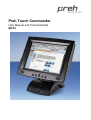
Preh Touch Commander
User Manual and Technical Data
MC15
Table of Contents
i. Model with multimedia base_________________________________________ 3
ii. Model number define: _____________________________________________ 4
1. General Points ___________________________________________________ 5
2. Contents of packing_______________________________________________ 5
3. Installation of Touchscreen_________________________________________ 6
3.1 Operating Conditions for the System___________________________ 6
3.2 Cable Installation and System Settings _________________________ 6
3.3 On Screen Display (OSD) _________________________________________ 7
3.3.1 OSD Control _________________________________________ 8
3.3.2 Key lock Function ___________________________________ 12
3.3.3 Hotkey Function _____________________________________ 12
3.4 Mechanical Adjustment of the LCD Position____________________ 13
4. Driver Installation ________________________________________________ 14
4.1 Magnetic Card Reader Setup ________________________________ 14
5. Care ___________________________________________________________ 15
6. Troubleshooting _________________________________________________
6.1 General Points ____________________________________________
6.2 Diagnostic Program ________________________________________
6.3 Troubleshooting list________________________________________
6.4 Additional help ____________________________________________
15
15
15
16
17
7. Technical Data __________________________________________________
7.1 Product Specification ______________________________________
7.2 Electronics:_______________________________________________
7.3 Touch: ___________________________________________________
7.4 Touch Controller __________________________________________
7.5 MSR (Option) _____________________________________________
7.6 Audio ____________________________________________________
7.7 ESD and EMC compliance___________________________________
7.8 Durability of mechanical bearing parts ________________________
7.9 Environmental conditions ___________________________________
18
18
19
19
19
19
20
20
20
20
8. Safety issues ___________________________________________________ 21
9. Further Information ______________________________________________ 22
10. Warranty ______________________________________________________ 22
11. Statement of Confirmation _______________________________________ 22
12. FCC Warning Statement _________________________________________ 23
2
3.2005
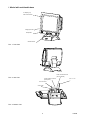
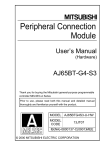
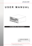
i. Model with multimedia base
LC-Display (15”)
with touch interface
swinging direction
loudspeaker
ON/OFF switch
Pict. 1: front view
serial connector RS 232
(touch controller)
Pict. 2: rear view
supply voltage connector
(main power)
MSR PS/2 Cable
VGA connector
audio cable
Pict. 3: bottom view
3
3.2005
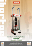
ii. Model number define:
MC15-T7xxM4Myy
LCD - Größe
LCD - Type
(TFT)
Touch
technology
LVDS + Touchkit
LVDS + ELO
15
T6
T7
resistiv seriell
R
Version
Multimedia (incl. Power Supply and Speaker)
Adapter plate (wall-mount)
Kartenmodul
MSR Spur 1+2+3 (seitlich)
Colour
weiß = white
schwarz = black
M
A
4
W
S
A
B
15,1“
Accessorier VGA- cable
VGA- cable & RS232- cable
Accessorier
Additional
remark
Power supply & german power cord
Power supply & UK power cord
Power supply & US power cord
Only for version with ELO touch foil and PT controller with ELO
original chip
GM
UK
US
(ELO)
Example:
MC15 T7RM4WbGM (ELO) =>
LCD size 15, ELO, resistiv, multimedia MSR
1/2/3, white, VGA & RS232 cable, power supply
& german cord (= reference 76504-084/4000)
4
3.2005
1. General Points
The Preh Touch Commander serves as graphical input device which makes the screen of
the computer react immediately on touching graphical operating characters (symbols,
keys, printings etc.). In this way the touchscreen allows simple, interactive handling of a
computer even for the PC-inexperienced user. For example this input media offers the
possibility of reducing training time and costs for the operating staff via a comfortable
user's dialogue. With its ergonomic design and its comfort in handling the Preh Touch
Commander is applicable in the fields of medicine, commerce, gastronomy, fast-food as
well in the restaurants and hotel business.
The Preh Touch Commander consists of two logical units, the active matrix color LCD
(TFT) and the highly sensitive touch sensor. These two units must be considered different
from each other in regard to their function. This means that the appearance of the picture
on the LCD (screen) is to be considered independent of the touch drivers. As far as the
computer is concerned the system is connected with the VGA output (LCD) as well as with
a serial interface (touching function).
The Touch Commander can thus take over the function of monitor and mouse. A
standard mouse can be used along with the Touch Commander. Both a standard
mouse and the Touch Sensor will control the position of the cursor on the screen.
The active matrix Color LCD (TFT) has a diagonal of 15" (381 mm) with a resolution of
1024x768 pixels as well as 262,144 colors. The display has an especially high degree of
brightness (typ.350cd/m²) and color brilliancy. The LCD parameters as for example
brightness, contrast, picture position etc. are adjustable via the On Screen Display (OSD).
The analog resistive 5 wire touch technology has a resolution of 1,024x1,024 points.
Inputting data is done by touching it e.g. with a finger. The activation force necessary to
register a touch is 1N. The touch surface consists of a hardened polyester foil with a high
resistance against scratches and an insensitivity to dirt, oil and water splashes. The
durability of the touch sensor is 35 million single actuation per touching point.
Multimedia models allow the possibility of giving the user audio feedback via sounds and
tones. The volume can be adjusted by a rotary control on the rear side of the base.
2. Contents of packing
Prior to operating your Preh Touch Commander, please check whether the following parts
are included and are in undamaged condition:
1 Preh Touch Commander
1 CD-Rom with touch driver for the operating systems DOS, Windows 3,1x/9x/NT/2000
XP and OS/2
1 VGA cable
1 serial cable
1 power cable
1 audio cable (only included with multimedia version)
5
3.2005
3. Installation of Touchscreen
Please read the following instructions prior to starting to use the Preh Touch Commander!
The following steps are necessary for a correct function of the device:
1 Adjust your computer for the proper video resolution [1024x768 / 60 Hz] and switch it
off, connect Touch, switch on computer and Touch Commander (see chapter 3.2). If
you are asked for confirming the new hardware "standard monitor", confirm according
to display instructions.
2 Adjust the video display on the Touch Commander for graphic card in the computer by
means of menu point "AUTO TUNING" of the OSD. This step is important for the best
quality of representation (see chapters 3.3).
3 Touch Commander:
Installation of touchscreen driver for the corresponding operating system
(see chapter 4).
3.1 Operating Conditions for the System
The Preh Touch Commander has been developed for the use with PC graphic adapters in
SVGA-setting with 1024x768 pixels of resolution. As an operating system it is necessary to
have either a DOS version 3.3 (or higher), Windows 3.1x, Windows 9x, Windows NT,
Windows 2000 Windows XP or OS/2.
For multimedia models a sound card with "Line Out" outputs for generating sounds is
necessary in addition.
3.2 Cable Installation and System Settings
The installation of the cables must be done with the computer switched off. Set the
correct screen resolution first. The optimum resolution is 1024x768 pixels and the refresh
rate 60 Hz.
To begin connect the VGA cable and the RS232 cable as well as the audio cable (see
pict. 3). Then plug in the AC power cable to the socket (see pict. 3).
If you now switch on the computer, the LED lights up green after about 3 seconds and the
corresponding picture appears on the screen. If the computer is in suspend or standby
mode the LED is red. If the SVGA cable between Touch Commander and computer is
disconnected, or that the computer power is switched off, the LED lights up red.
6
3.2005
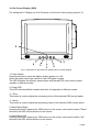
3.3 On Screen Display (OSD)
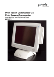
For setting the LC Display you find 5 buttons on the front of the housing (see pict. 5).
LED
2
6
3
5
1
4
Pict. 5: Description of the buttons for perating the On Screen Display.
1. Power Switch
Pressing this button turns the display system power on or off.
When the power switch are switch on, this LED lights in green.
The LED indicates the different power status with altered LED colors when monitor
operates in different modes
2. Power LED
This LED indicates different states when this unit operates in different modes.
3. + Plus
This button is used to adjust the increasing value of the selected OSD control option.
4. - Minus
This button is used to adjust the decreasing value of the selected OSD control option.
5. Menu/Select Right
Pressing this button pops up the OSD menus on the screen, and used to select ("Down"
direction) the OSD control options on the screen.
6. Menu/Select Left
Pressing this button pops up the OSD menus on the screen, and used to select ("Up"
direction) the OSD control options on the screen.
7
3.2005
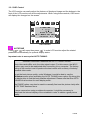
3.3.1 OSD Control
The LCD monitor can easily adjust the features of displayed image and the buttons in the
front of the LCD monitor can do the adjustments. When using these controls, OSD menu
will display the changed on the screen.
OSD MENU
‧ AUTOTUNE
Press
or
call menu then press „
“ to make LCD monitor adjust the related
parameters automatically for optional display status.
Important note to menu point AUTO TUNING:
Important information regarding the AUTO TUNING function.
Most video cards differ as to the video signal output. For this reason, the MC15
monitor may need to be readjusted after connecting it to a computer. The factory
setting of the monitor is set to produce the best results with a variety of industry
standard video cards.
To get the best picture quality, under Windows it would be best to use the
Shutdown screen when activating the AUTO TUNING menu option. By doing this,
the display tries to find the best possible adjustment. Please note that this AUTO
TUNING must be done for each display mode.
The PHASE option may also be used to manually fine tune the picture clarity after
AUTO TUNE has been done.
In some cases when using a notebook computer, it might be necessary to
deactivate the internal display of the notebook in order to obtain a good picture
quality.
8
3.2005
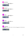
‧ BRIGHTNESS
Adjust the value using
and
buttons.
and
buttons.
and
buttons.
and
buttons.
‧ CONTRAST
Adjust the value using
‧ CLOCK
Adjust the value using
‧ PHASE
Adjust the value using
‧ H-POSITION
Pressing
to the left.
moves the display image to the right; pressing
9
moves the display image
3.2005
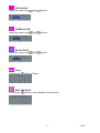
‧ V-POSITION
Pressing
moves the display image to the upward; Pressing
image to the downward.
moves the display
‧ OSD H-POSITION
Pressing
the left.
moves the OSD image to the right; pressing
moves the OSD image to
‧ OSD V-POSITION
Pressing
moves the OSD image to the upward; pressing
the downward.
moves the OSD image to
‧ Overlapped Mode
Pressing the
button to Overlapped Mode.
The "UserPrefOverlappedMode" variable is used to control the overlapped mode and the
bits are set based
on the current mode to the other mode. If the current input width is 640, then it sets the
"UserPrefOverlappedMode" to DOS; and if the width is 720, then it sets the variable to
Graphics to change the input width.
However this variable is cleared after the mode setup for the next new mode. Therefore
this variable does not need to be saved in the NVRAM.
‧ VOLUME
Adjust the value using
and
buttons.
10
3.2005
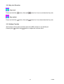
‧ RED COLOR
Adjust the value using
and
buttons.
and
buttons.
and
buttons.
‧ GREEN COLOR
Adjust the value using
‧ BLUE COLOR
Adjust the value using
‧ Reset
Pressing the
button to Reset.
‧ EXIT AND SAVE
Pressing the
button to save changed value and exit.
11
3.2005
3.3.2 Key lock Function
‧ Key lock
Press and hold the
button (first) and
button for 6 sec to activate the Key lock.
button (first) and
button for 6 sec deactivate the Key lock.
‧ Key unlock
Press and hold the
3.3.3 Hotkey Function
This function will only be activated when the OSD function is not started yet.
Pressing the
button and
button to adjust the volume value.
12
3.2005
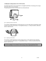
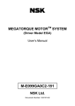
3.4 Mechanical Adjustment of the LCD Position
The LCD of the Preh Touch Commander is swingable and tillable. According to the usage
the LCD position can be changed.
The below picture shows the model with the multimedia base.
Pict. 6: adjusting screws on rear side
The infinitely variable adjustment of the tilting force can be made with two adjusting screws
located on the rear of the monitor. The adjustment torque (1 - 8 Nm) should be about the
same on both screws.
Pict. 7: adjusting screws below
The infinitely variable adjustment of the swinging force can be made with two adjusting
screws in the base of the monitor. The adjustment torque (1 - 8 Nm) should be about the
same on both screws.
Note: On changing the housing position you should be careful to not get your fingers too
near to the opening on the rear side of the housing as they might get pinched there.
13
3.2005
4. Driver Installation
Important Note:
A new calibration is always necessary if another touchscreen was connected to the
computer or if the screen resolution was changed. This means that the calibration between
touchscreen and computer is adjusted to the mechanical features of the particular
touchscreen which was connected to the computer at that time.
A serial Touch Controller is integrated into the Touch Commander. The default setting is
9600 Bps. Normally this is clearly recognized by the setup programs. If, however, it is not
clearly recognized, the adjustment can be done manually or by restarting the
corresponding setup program.
Information for the driver installation is in the file:
D:\MC15\TOUCH\TouchKit\...
(MC15 T4, T5 or T6)
D:\MC15\TOUCH\ELO\
(MC15 T7)
You can find detailed information in the path, named with your operating system. (The CDROM drive of your Tocuh-CD is here defined with the letter „D“).
4.1 Magnetic Card Reader Setup
The setup utility can be found on the installation CD at:
D:\MC15\MSR\PS2\MSR Utility Manual.pdf
(Drive D:\ shown above may vary on each system.)
14
3.2005
5. Care
Before cleaning, switch off the power supply. A soft cloth moistened with a mild cleaning
agent can be used for cleaning the housing. For cleaning the screen it is better to use a
soft paper towel moistened with a mild household cleaning agent. For cleaning the surface
do not apply the cleaning liquid directly but use a moistened paper towel. Please avoid
getting liquid into the housing.
6. Troubleshooting
6.1 General Points
Attention:
The Preh Touch Commander does not contain any electronic components that can be
replaced or repaired by the user. Consequently you should not try to do your own repair
work. Moreover, you would lose all warranty claims for this product. Activating the touch
sensor surface must not be done with a sharp object, such as credit card, long finger nails,
ring, etc. Sharp or pointed objects will cause damage to the touch sensor and are not
covered under warranty
If the Touch Commander must be returned for service, it must be packed in it's original
packing material. If this is not done, the sender will be made responsible for possible
transport damage.
6.2 Diagnostic Program
The diagnostic program COMDUMP is located in the path D:\TOUCH\MONTEST. It is
started in DOS mode or command prompt whereby the COM connection must be stated;
the baud rate is optional.
COMDUMP <number of COM port 1 or 2> [baudrate]
COMDUMP will then show you the data coming from touchscreen to COM port in
hexadecimal data on the screen. If you now contact the touch sensor the sent data should
be seen on the display.
15
3.2005
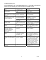
6.3 Troubleshooting list
A lot of malfunctions can be traced back to incorrect or loose cable connection. So
please make sure that all plug connections are correct and secured.
Fault
Possible cause
LED on Touch Commander voltage supply not in
remains dark
order
computer switched off
LED on Touch Commander VGA cable is not
lights up red and no picture correctly connected
appears
The display shows only
choice of display
part of the picture or the
resolution is wrong
picture is distorted
display adjustment
insufficient
LCD shows indistinct
display ("HORIZONTAL
vertical stripes
SIZE") is insufficiently
set
LCD shows fine horizontal display ("PHASE") is not
stripes
correctly adjusted
Touch cannot be calibrated
under the operating
systems of Windows,
button "calibrate" is
deactivated
Vertical streaks in LCD
image
cable connection
incorrect
Calibrating program
notifies error when called
up
touchscreen driver not
correctly installed
OSD menu can not be
accessed
Key lock is activated
Display “Clock” or
“Horizontal Position”
improperly set
16
Remark
check plug-in connection of
power supply
switch on the computer
check cable connection of
VGA connection
check for correct display
resolution it should be
1024x768 or less
see notice to adjustment of in
chapter 3.3
set horizontal size of picture
in menu IMAGE POSITION of
OSD(see chapter 3.3.1)
adjust PHASE in menu
BASIC-SETTINGS of OSD
(see chapter 3.3.1)
check serial connection,
restart computer
Set horizontal position and
size of picture in menu “HPosition”and “Clock” of OSD
(see chapter 3.3.1)
Set the driver again with
SETUP or with button setup
in the calibrating program.
Here the serial connection
should be correctly entered
and the correct controller
should be selected. Check
the serial cable connection
Deactivate Key lock (see
chapter 3.3.2)
3.2005
6.4 Additional help
If you have problems with the connection and the installation of the Preh Touch
Commander, please contact your dealer.
You can contact Preh KeyTec Technical Support at:
Germany/World wide:
Email:
[email protected]
fax:
+49 (9771) 92-152
USA/America:
EMail:
fax:
[email protected]
+1 847-438-4053
17
3.2005
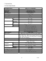
7. Technical Data
7.1 Product Specification
Configuration
LCD Display
Display Size
Pixel Pitch
Max. Resolution
Contrast Ratio
Brightness
Response Time
Display Color
Viewing Angle
MC15-T7XXM4MX
15” TFT active matrix panel
304(H)x228(V) mm
0.297(H)x0.297(V) mm
XGA 1024x768
400:1
350 cd/m2
6/17 ms
262,144
L/R
60∘ ~ 60∘
U/D
40∘ ~ 60∘
Swivelling
39∘ +/- 3∘
Tilt
PC Interface
Video
Sync.
Display Mode
Signal Connector
Front Control
OSD
Plug & Play
Speaker
Power
Operating
Conditions
Storage
Conditions
40∘ +/- 3∘
RGB analog 0.7V peak to peak
TTL positive or negative
VGA 640x400 (60/70 HZ)
VGA 640x480 (60/72/75 HZ)
VGA 720x400 (70 HZ)
SVGA 800x600 (60/70/72/75 HZ)
XGA 1024x768 (60/70/72/75 HZ)
D-sub 15 pin
Menu, Left, Power on/off with LED, Right, Select
AutoTun, Brightness, Contrast, Color, Phase, H-POS, VPOS, OSD H-Pos, OSD V-Pos, Volume, Red Color, Blue
Color, Green Color, EXIT AND SAVE,Reset, Overlapped
Mode, Key lock Function
DDC1/2B compatible
Active Speaker
Input: AC 110-240 Volts, 47 – 63 Hz,
Output: DC 12V/4A
Temperature
0℃ - 40℃ (32℉ - 104℉)
20%~ 85%
Humidity
Temperature
-10℃ - 60℃ (-4℉ - 140℉)
5%~ 85%
typ.50,000 h
Multimedia / Wall Mount
Option / RS232 Interface
Option / Three tracks
UL,CUL, FCC, TUV/GS, CE
Humidity
Life of background illumination
Base Type
Touch Screen
Magnetic Stripe Reader
Certification
* Specifications are subject to change without notice.
18
3.2005
7.2 Electronics:
Following specifications are for the multimedia model only:
Line voltage:
Power consumption
100-240 AC, 47-63 Hz, 0.6A
max. 20 W
7.3 Touch:
Interface:
Technology:
Resolution:
Surface:
Transmission:
Durability
RS232, Mouse Emulation under DOS, Windows 3 x,
Windows 9x, NT, 2000, XP, Linux and OS/2
5-wire resistive
max. 2048*2048
hardcoated polyester foil
75%
35 million actuation
7.4 Touch Controller
Controller:
Power Requirement:
Operating Temperature:
ELO Coach 115275-000
5V/100mA
0 to 70℃
Storage Temperature:
-65℃ to 150℃
Relative Humidity:
Interface:
Protocol:
95% at 60℃
RS232
8 data bit, 1 stop bit, 9600 baud (N, 8, 1, 9600)
7.5 MSR (Option)
Interface:
Track:
Decode:
Scan direction:
Power Supply:
Power consumption:
Durability:
Card Spec:
Reading Track Width:
Card Feeding Speed:
PS/2
Three Tracks
KB Interface
Right Side scan.
5V DC ±5%
Less than 20mA
500,000 cycle.
ISO7811
1.5mm
10 ~ 120 cm/sec(4-50inch/sec)
19
3.2005
7.6 Audio
Amplifier Controller:
Output:
Power:
Control Method:
Frequency:
TDA7496L
2W/Ch.
12V/25mA
PWM Adjust.
20 ~ 20KHz
7.7 ESD and EMC compliance
CE-sign (see also Statement of confirmation)
Radiated Emissions: EN55022, class B
FCC part 15, class B
Susceptibility
Compliance:
1. electrostatic discharge according to EN 61000-4-2
(hardness air +,-8KV and contact +,- 4KV)
2. high frequency electromagnetic fields EN 61000-4-3
(hardness Modulation 3 V/m),
3. fast transient/burst immunity electrical interference
features according to EN 61000-4.4 (Criteria B:
hardness 1 kV for AC power)
4. Surge immunity test according to EN 61000-4-5
(Criteria B)
5. Immunity for conductive disturbance test according
to EN61000-4-6(Criteria B: level is 3V Modulation)
6. power frequency magnetic field test EN 61000-4-8
(Criteria B: 1A/m)
7. voltage dips , short interrupt and voltage variation
immunity EN 61000-4-11(Criteria B)
8. power harmonics test EN 61000-3-2(Criteria A:<=75W)
9. voltage fluctuation test EN 61000-3-3
7.8 Durability of mechanical bearing parts
Tilting and swinging
1.000 cycles typical
7.9 Environmental conditions
Operating amibent temperature:
Storing temperature:
Relative humidity of air:
Air pressure:
0°C...50°C
-20°C...60°C
10%...90% (at max. 35°C)
700hPa...1060hPa
20
3.2005
8. Safety issues
Please read these instructions carefully before connecting the unit to any AC-mains and
keep the instructions also for later use.
The multimedia type is belong to Class I type and the wall mount type is belong to Class III
type for power consuming configuration.
First check the power values of your AC-mains with the datas of this device, before
connecting to any wall-plug socket.
Place the unit as close as possible to your wall-plug socket and make sure, that the mains
connector is easily accessable. Make also sure, that there are no other equipments placed
on the cable and also that it’s placed in a way, that nobody can fell over it. If the unit is not
in use for a longer period, it should be disconnected from mains.
Protect the device from any liquids and high humidity. Do not operate the unit outdoors.
Unplug the device from the wall-plug socket immediately and have it checked by a
qualified Service person in case:
• the mains cable or connector is being damaged
• liquids have been penetrated into the device
• the device has been exposed to the elements (dampness/rain)
• the device does not operate as to the operating instructions
• the device has been dropped and / or shows outside damages (i.e. cabinet)
• the device shows markable performance of deffects
Do not open the device on your own as there is dangerious voltage inside. Apply to the
Service or your dealer for any repair issues.
Do not drink liquid crystal leaking from the LCD in case of a damage. If such leakage
touches your skin, clean it by water & soap, immediately.
The working place related sound pressure level (DIN 45 645) of the device is less
then70dB(A)
It it only permitted to use tested / certified power cables H03VV-F.3G, 0.75 and / or better
ones.
The maximum environment temperature is 40 degrees Celsius
GS and ISO 9241-7 for class III certified Screens will meet its classification under the
following conditions:
• the operation of the screen complies to suitable working place illumination
environment
• the screen shall not be placed in front of a window or direct light
21
3.2005
9. Further Information
All Preh KeyTec products are subject to a continuous process of improvement. For this
reason we reserve the rights of technical modifications.
We point out that inadequate handling, storage, influence and/or modification can cause
disturbances and damage in usage.
In case you modify our products in any way we do not assume warranty and liability unless
you have an explicit release in writing for your specific case.
This applies especially to unprofessional repair and maintenance jobs.
Any claims for damages against the Preh works – no matter for which legal reason – are
excluded if no intention and gross negligence can be proved. Above limitation do not apply
to claims for damages out of the product liability law.
This Operator's Manual is exclusively valid for the product Preh Touch Commander
supplied with it.
10. Warranty
Preh KeyTec guarantees that all products supplied are free from production and material
faults. The period of warranty is two years and begins with the date of delivery.
Otherwise the general sales conditions of the Preh KeyTec company are valid.
11. Statement of Confirmation
This is to certify that statements of confirmation are available for all different versions of
the Preh Touch Commander.
You can request a copy from Preh KeyTec stating the exact type description (see type
label on the bottom of the device).
Preh KeyTec GmbH
An der Stadthalle
D-97616 Bad Neustadt an der Saale
Germany
Fax: +49 (9771) 92-152
Web: www.preh-keytec.com
22
3.2005
12. FCC Warning Statement
Note: This equipment has been tested and to comply with the limits for Class B or Class A
digital device, pursuant to Part 15 of the FCC Rules. These limits are designed to provide
reasonable protection against harmful interference in a residential installation. This
equipment generates, uses and can radiate radio frequency energy and, if not installed
and used in accordance with the instructions, may cause harmful interference to radio
communications. However, there is no guarantee that interference will not occur in a
particular installation. If this equipment does cause harmful interference to radio or
television reception, which can be determined by turning the equipment on and off, the
user is encouraged to try to correct the interference by one of the following measures:
•
•
•
•
Reorient or relocate the receiving antenna.
Increase the separation between the equipment and receiver.
Connect the equipment into an outlet on a circuit different from that to which the
receiver is connected.
Consult the dealer or an experienced radio/TV technician for help.
Shielded interface cables must be used in order to comply with the emission limits.
Caution:
Changes or modifications not expressly approved by the party responsible for
compliance could void the user’s authority to operate the equipment.
Copyright
© Copyright Preh KeyTec GmbH 2005
Published by Preh KeyTec GmbH
All rights reserved. Reproduction in any manner, in whole or in part, is strictly prohibited without the written permissin of Preh KeyTec
GmbH. The Information in this document is subject to change without prior notification for the sake of improving reability, design and
function.
Trademarks
All brand and product names are trademarks or registered trademarks of their respective companies.
23
3.2005