1
USER MANUAL
PRESSURE SAND BLASTERS
MODELS
U100-0
U100-S
U103-0
U103-S
UNI-RAM CORPORATION • ONTARIO • CANADA
Revised 2006-02
MANUAL - SANDBLASTERS - U100-U103
Revised 2006-02
CONTENTS
INTRODUCTION ................................................................................................................................... 3
CAUTIONS ........................................................................................................................................... 3
PREPARATION....................................................................................................................................... 4
OPERATING INSTRUCTIONS ........................................................................................................... 4-5
SEAL BLOCK ADJUSTMENT ................................................................................................................ 6
SAFETY SHUT OFF CONTROL ........................................................................................................... 6
FEATURES, SPECIFICATIONS AND BREAKDOWN .......................................................................... 7
KEY PARTS .......................................................................................................................................... 8
REPLACEMENT HOSES, NOZZLES, HOODS AND ASSEMBLIES ..................................................... 9
WARRANTY ......................................................................................................................................... 10
2
MANUAL - SANDBLASTERS - U100-U103
Revised 2006-02
INTRODUCTION
Uni-ram holds many patents on designs used in its innovative products. Every machine is rigorously
tested for compliance with stringent Quality Assurance standards. Follow the straight forward Operating Procedures closely in order to operate this machine safely and effectively. Ensure that this manual is
readily available to the operator at all times. If you have any questions about the operation of this machine, contact:
North America:
Uni-ram Technical Service
1-800-417- 9133
Other Continents:
Contact Your Supplier
CAUTIONS
•
•
•
The operator should wear protective clothing with a minimum of gloves and goggles
Relieve the pressure in the tank when the unit is not in use
Repair any air leaks as soon as possible to avoid serious damage
3
MANUAL - SANDBLASTERS - U100-U103
Revised 2006-02
PREPARATION
IMPORTANT: OPERATOR SHOULD WEAR PROTECTIVE CLOTHING
Note: Item numbers given below refer to the parts listing on page 4.
1. On removal of sandblaster from carton, check for any transportation damage and make sure all parts
and accessories are included.
2. Make sure the Air Shut Off Valve (Item 8) is closed.
3. Make sure the Sand Flow Control Valve Item 11) is closed (handle in horizontal position).
4. Make sure the Nozzle End Shut Off Valve at the end of the Blast Hose is closed.
5 The choice of nozzle size is limited by the CFM air capacity of the compressor. For fast cutting or
cleaning, the nozzle should be no larger than necessary to permit the compressor to maintain 80
pounds of pressure when blowing continuously. Thus, 1/8” nozzles are supplied as standard parts for
the ½” sand hoses. This hose can be used for sand, steel grit and shot. See the previous page for
nozzle specifications.
6. All sand should be dry and uniformly graded to about #30 screen size for use with 1/8”, 3/32’ or 7/64”
nozzles. With larger nozzles, coarser grade grit, shot or beads may be used.
7. TO FILL THE SANDBLASTER – Make sure the Sand Flow Control Valve (Item 11) is closed, then:
a) Remove Filler Valve (Item 4) to make filling easier
b) Fill the tank from the top, making sure the abrasive is dry and running freely
c) Connect the air hose to the Air Shut Off Valve (Item 8)
d) Replace the Filler Valve and hold in place while you open the air valve and allow the tank to fully pressurize (about 20-30 seconds). The air pressure will then hold the Valve in place.
OPERATING INSTRUCTIONS
1. WHEN YOU ARE READY TO SAND BLAST: Open the Nozzle End Shut Off Valve at end of the Blast
Hose, then gradually open the Sand Flow Control Valve (Item 11). The valve first passes air only, then
increasing amounts of sand. When you have enough sand for the desired cutting effect, operate with the
Nozzle End Shut Off Valve if one is supplied. This valve is not for mixing and should be used either wide
open or closed. NOTE: You can tell when a good operating level has been reached by the cutting effect of
the abrasive when it hits the surface and by the “feeling” of the abrasive rebound force.
2. TO RELIEVE PRESSURE IN THE TANK: To refill or change nozzles etc, shut off the Air Shut Off Valve
(Item 8). Open the Pressure Relief Valve (10-251F) by inserting a finger into the ring and pulling downward. IMPORTANT: It is recommended that the pressure be relieved whenever the unit is not being used
because air held in the tank under pressure can cause moisture condensation which can clog the sand
control valve. If the valve does get clogged, open the square-headed Drain Plug (Item 13) or the Filler
Valve and agitate the abrasive with a rod or wire.
3. TO EMPTY THE SANDBLASTER: Relieve the pressure as above, remove the Filler Valve (Item 4) and
open the Sand Control Valve (Item 11). Then remove the square-headed Drain Plug (Item 13) from the
bottom of the tank to drain the abrasive. NOTE: With the Filler Valve removed, abrasive may be vacuumed out through the top of the tank.
4
MANUAL - SANDBLASTERS - U100-U103
Revised 2006-02
OPERATING INSTRUCTIONS (continued)
4. OPERATING TIPS:
a) Always operate with hose and control “wide open”. Adjustment for suitable abrasive flow should be
made independently using the Sand Flow Control Valve (Item 11).
b) Make sure you match the right combination of abrasive type and mesh size, nozzle size and air pressure to the particular job at hand.
c) Nozzles should be changed whenever they wear sufficiently to lose their cutting power at lower than
80 PSI. Your efforts become inefficient after the nozzle orifice has worn to more than 11/2 times its
original diameter.
d) Use Tungsten Carbide nozzles for long, continuous operations.
e) If the unit has a Moisture Filter, check and drain it periodically by opening the valve at the bottom while
it is under pressure.
f) Repair the cause of any air leakage as soon as possible to avoid serious damage.
f) If an abrasive clog forms in the bottom of the tank, the Anti-clogging Valve (Item 17) may be used as
follows to remove the blockage:
• Open the Nozzle End Sut Off Valve and hold it open if necessary
• Make sure the Sand Flow Control is open
• Open the Air Shut Off Valve
• Open and close the Anti-clogging Valve repeatedly to send a series of air “pulses” down through the
tank. If the blockage remains, remove the Drain Plug (Item 13) and use a wire or rod to open the passage. For normal operation, leave the Anti-clogging Valve open.
5. REPLACEMENT OF HEAVY-WEAR PARTS: Keep a supply of quickly wearing consumable parts such
as ceramic nozzles, seal blocks, nozzle holder washers, plastic hood lenses etc on hand. Purchase
ahead of time if necessary.
6. NOZZLE SPECIFICATIONS: Sand and air consumption and the area cleaned depend on the type of
abrasive, air pressure, nozzle size and the condition of the surface to be cleaned.
NOZZLE
SIZE
MINIMUM
COMPRESSOR
AIR USED
(CFM AT 80 PSI)
SAND USED
(LB PER HOUR)
AREA CLEANED
(SQ FT PER MIN)
3/32”
5 HP
7
80 TO 100
0.5
1/8”
5 HP
30
200 TO 210
1 TO 1.5
5/32”
5 HP
30
200 TO 210
1 TO 1.5
3/16”
5-10 HP
45
300 TO 350
3.0 TO 3.5
1/4”
5-10 HP
80
500 TO 600
4.0 TO 4.5
5/16”
10-15 HP
125
800 TO 950
6.0 TO 7.0
7.
a)
b)
c)
d)
e)
MISCELLANEOUS:
The pressure vessels are manufactured to ASME standards.
All models come with a ½” ID Sand Hose.
Nozzle sizes range from 3/32” to 5/16”
Heavy steel grit or shot can be used with the ½” Sand Hose using 5/32” to ¼” nozzles.
For larger nozzles (3/16”, 5/16”) a ¾” ID Sand Hose is recommended.
5
MANUAL - SANDBLASTERS - U100-U103
Revised 2006-02
SEAL BLOCK ADJUSTMENT:
1. Proper adjustment is important to ensure efficent operation and prevent excessive wear of the Seal
Block.To accomodate size variations in the manufacturing of ceramic nozzles, elongated adjustment holes
are provided for seating the Seal Block. Fix the Seal Block in place by tightening the Seal Block Nut so
that the end surface of the Nozzle is in close contact with the Seal Block when the Control Lever is in the
closed position. There should be no gap between the two surfaces. Air leakage will be minimal but some
noise from escaping air is normal.
2. Each Seal Block can be used four times by changing the surface used. To change the surface, loosen
the lock nut and rotate the block to a new surface.
3. When a new nozzle is installed, the Seal Block must be readjusted to fit tightly against the new nozzle.
SAFETY SHUT OFF CONTROL - U5000F
1. OPERATION: To open the Control, squeeze the lever quickly. To close, release the lever quickly. To
avoid exposing the Seal Block to abrasive, do not open or close the Control slowly. Use the U5000F as
a working control only. When the job is finished, close the Sand Flow Control Valve (Item 11) and the Air
Shut Off Valve (Item 8), then release the air pressure by opening the Pressure Relief Valve by inserting a
finger into the ring and pulling downward.
2. REPLACEMENT:
a) Remove the Handle Tube from the Retainer Nut by turning the nut counter-clockwise.
b) Make sure the end of the hose is cut flat and square.
c) Apply grease to the outside of the hose for approximately 21/2” from the end.
d) Insert the hose into the Handle Tube making sure it is pushed firmly into the tube approximately 21/2”.
e) Secure the hose using the six screws provided.
f) Hold the Retainer Nut using a bench vise or vise grips and attach the Handle Tube by turning it clockwise with a pipe wrench. Make sure the Tube is firm and tight.The Seal Block is pre-adjusted at the factory to the Ceramic Nozzle supplied. If necessary, adjust the Seal Block as above to fit your nozzle and
minimize air leakage.
6
MANUAL - SANDBLASTERS - U100-U103
Revised 2006-02
Uni-ram Pressure Sand Blasters are portable, rugged, efficient tools for removing dirt, rust,
paint and other materials from all kinds of surfaces.
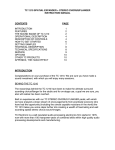
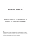
FEATURES, SPECIFICATIONS AND BREAKDOWN
• SUITABLE FOR USE WITH MANY ABRASIVES INCLUDING: SILICA SAND, GLASS BEADS,
METAL SHOT, ALUMINUM OXIDE, NUT SHELLS, BAKING SODA
• HEAVY DUTY 4-PLY HOSE
• DURABLE POWDER PAINT
• AIR INLET SHUT OFF VALVE
• MAINTENANCE-FREE REMOVEABLE FILLER PLUG
• PORTABLE WITH HEAVY DUTY WHEELS
• PRESSURE GAUGE
• WORKING PRESSURE: 125 PSI
• FUNNEL TOP DESIGN
• ABRASIVE FLOW CONTROL
VALVE
• PRESSURE RELEASE VALVE
(140 PSI)
MODEL
U100-0
U100-S
U103-0
U103-S
NOZZLE END SHUT OFF
NONE
U5000F
1/2” STEEL
U5000F
MOISTURE FILTER
X
X
QUICK COUPLINGS
X
X
CAPACITY (LB)
90-100
90-100
100-110
100-110
8
8
10
10
SHIPPING SIZE (W X D X H“)
17X17X35
17X17X35
17X17X35
17X17X35
SHIPPING WEIGHT (LB/KG)
55/25
55/25
58/26.4
58/26.4
NO. OF NOZZLES (10-260)
2
2
3
3
HOSE LENGTH (FT)
Item
Part No.
Description
1
10-121
O-Ring Gasket, Filler Plug
2
10-128
Filler Valve Plug Block
3
10-125
T-Handle Only
4
10-120
T -Handle Stem Filler Valve complete
5
10-131
Heavy Duty Pressure Gauge
6
12-601
Air Manifold Distributor Block
7
12-220
Moisture Filter (U103)
8
10-231
Air Shut Off Valve
9
10-245
Hose Clamp, 1&1/8”
10
11-241
Air Pressure Input Hose
11
10-171
Sand Flow Control Valve
12
10-176
Cross Union Connector
13
10-173
Drain Plug, Square Head
14
11-161
Wheel, 6” Heavy Duty
15
27-384
Wheel Cap, 1/2” Axle
16
10-168
Leg Support Ferrule
17
10-231
Anti-clogging Valve
18
10-251F
Pressure Release Valve (140 PSI)
19
11-640
Inlet Adapter, 4 Holes
7
MANUAL - SANDBLASTERS - U100-U103
Revised 2006-02
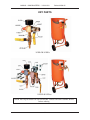
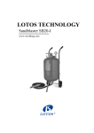
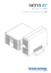
KEY PARTS
U100-0 & U100-S
U103-0 & U103-S
NOTE: Not all parts shown are user serviceable. Contact Uni-ram Customer Service
before ordering.
8
MANUAL - SANDBLASTERS - U100-U103
Revised 2006-02
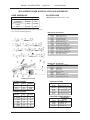
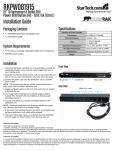
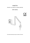
REPLACEMENT HOSES, NOZZLES, HOODS AND ASSEMBLIES
HOSE ASSEMBLIES
PART NUMBER
BLASTER HOSE
10-150
10-151
HOSE LENGTH (FT)
8
10
CONNECTORS
NOZZLE END ON/OFF
CONTROL
THREADED
QUICK
NONE
1/2" STEEL
MODEL
U100-0/S**
U103-0
10-159 Hose per Foot, 1/2" ID, 1" OD
*Also called "Safety Blast Hand Control", "dead man switch" or "squeezer gun".
**For U100-S model, add U5000 Safety Shut Off
ITEM PART NO. DESCRIPTION
1
2
3
4
5
6
7
8
9
10
11
13
14
15
16
17
10
10-260
10-501
10-516
10-511
50-401
10-420
10-517
10-431
U5000F
10-159
10-230
10-246
10-281
10-287
10-182
10-184
Ceramic Nozzles (see below)
Nozzle Retainer Nut
Bushing, Rubber, Short
Reducer Holding Nut
Handle Tube, Plated
Handle Tube, Plastic Cover
Bushing, Rubber, Long
Handle Tube, Threaded
Safety Shut Off (Hand Control)*
Hose per Foot, 1/2"ID/1"OD
On/Off Control, 1/2" Carbon Steel
Hose Clamp, Crimp Type, 1/2"
Hose Connector, Male, Barb
Hose Connector, Female, Tube
Quick Connect, Male, 1/2"
Quick Connect, Female
ITEM PART NO. DESCRIPTION
1
2
3
4
5
6
7
8
9
U5000
Safety Shut Off, Complete
50-101
Lever Handle
50-501
Seal Washer
50-301
Return Spring
50-201
Retainer Nut
Ceramic Nozzles (see below)
50-002
Seal Block
50-590
Bolt, Nut and Washer Assy
50-401
Handle Tube, Plated
50-411
Hose Retention Screws (4)
U5000F SAFETY SHUT OFF
EXTENSION HOSES
HOODS and LENSES
PART NO.
LENGTH
CONNECT
PART NO.
DESCRIPTION
10-157
10-158
10-159
10'
20'
ANY
QUICK
QUICK
NONE
10-300
10-301
10-305
10-306
10-400
10-401
Cotton hood with 4 lens
Cotton hood, 4 lens, h. hat
Lens for hood, 5x6.5", one
Lens, 5x6.5", Pkg of 10
Vinyl hood with back vent
Lens, single, 8.75x7.5"
CERAMIC NOZZLES
CFM
@ 125 psi
#1 - 10-263
3/32
10
#1 - 10-260‡
1/8
28
#1 - 10-264
5/32
47
#1 - 10-261
3/16
70
#1 - 10-262
1/4
125
#1 - 10-265
5/16
187
#2 - 10-270
1/8
28
‡Standard size shipped with new equipment
PART NO.
ID (")
TUNGSTEN CARBIDE NOZZLES
PART NO.
10-020S
10-030S
10-040
10-040S
9
DESCRIPTION
and ID (")
Short Nozzle, 1/8
Short Nozzle, 3/16
Long Nozzle, 1/4
Short Nozzle, 1/4
MANUAL - SANDBLASTERS - U100-U103
Revised 2006-02
Full Product Warranty
These Uni-ram products have been engineered and manufactured to high performance
standards. Each unit has been subjected to detailed factory testing before shipment.
This product comes with a one-year full warranty from the date of purchase. Uni-ram
Corporation reserves the right to repair or replace the unit, free of charge, to the original
purchaser if a part is found to be defective in material or workmanship as determined
by factory service personnel. The items listed below under “Conditions of Warranty” as
consumables are not covered.
Uni-ram reserves the right to direct the customer to ship the unit collect to the Uni-ram
factory or to an approved Service Center for repair using the Uni-ram Return Goods
Procedure or to repair the unit on-site. To prevent damage in transport, the purchaser
must ship the unit in the original packaging or use alternate adequate packaging. All
units must be shipped clean and free of solvent.
Conditions of Warranty:
As Uni-ram Corporation has no control over the working conditions or circumstances
under which the purchaser stores, handles or uses the product, Uni-ram makes no warranty or claim, either expressed or implied with respect to this product’s fitness for any
purpose or the result to be obtained from its use. This condition applies to the sale of all
products and no representative or distributor of Uni-ram Corporation has the authority to
waive or change these conditions.
This warranty applies only to the original purchaser and does not apply if the unit has
been misused, overloaded, neglected, altered or used for any purpose other than those
specified in the operating and installation instructions. Deterioration due to normal wear
is not covered by this warranty. Damage due to accident, transportation, fire, floods
or acts of God is also not covered. Units whose serial numbers have been altered or
removed are not covered. The warranty is invalid if unauthorized abrasives are used in
this unit. Unauthorized attempts at self-repair or alterations by the owner also invalidate
this warranty. Interior or exterior finishes are not covered by this warranty.
Consumable Items are not covered by this warranty.
This warranty replaces all other warranties expressed or implied by statute or otherwise.
To make a claim, call Uni-ram Service at 1-800-417-9133 and quote the serial number
of the unit.
10
INSIDE BACK COVER