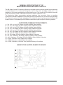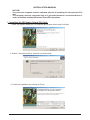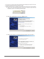
1
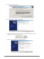
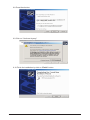
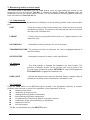
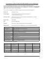
BS Quatro Guard PCI MONITORING STATION FOR CONNECTING TO ARMED SITES OVER A TELEPHONE LINE NOTE This manual contains information on the limitations of the use and operations of the product and information on the limitations of the liabilities of the Producer. This Manual must be studied carefully. The Producers reserves the right to make unnoticed modifications. 02\2006 CONTENTS General Specifications of the Monitoring Station 4 Supported Communication Formats 4 Image of BS Quatro Guard PCI Board 4 Installation Manual 5 Installing the BS Quatro Guard PCI Card 5 Installing the Computer Software 10 User’s Manual 10 Start-up and Initialisation 10 Data Perception Procedure 10 Monitoring Station Control Panel 11 Adjustments 11 Options 11 Log File 11 Programme Operation Error Report 12 PowLink.INI. Section File [BSGuard] 12 Installation of MS ACCESS DATA BASE DRIVER (UniversalBSGuard) 13 Warranty 15 3 GENERAL SPECIFICATIONS OF THE MONITORING STATION BS Quatro Guard PCI The BS Quatro Guard PCI Monitoring Station is intended to perceive alarm signals from armed sites over the telephone line. It has been designed as a PC card, which emulates a serial port. It can maintain up to 4 concurrent telephone communication lines. The number of PCI slots the computer avails of limits the number of BS Quatro Guard PCI cards, installed on a PC. The Monitoring Station permanently registers telephone line connection failure or possible connection of derivative apparatus. BS Quatro Guard PCI operations rely on user-friendly Windows NT software for easy and ready adjustment. The statistical report log management facilitates BS Quatro Guard PCI compatibility with LRR8000 radio alarm signal reception monitoring stations. SUPPORTED COMMUNICATION FORMATS: 1 – 3x1, 3x2, 4x1, 4x2; SP=10pps; HS=KO=1440Hz; Data=1900Hz; 2 – 3x1, 4x1; SP=10pps; HS=KO=1440Hz; Data=1900Hz; Extended 3 – 3x1, 3x2, 4x1, 4x2; SP=20pps; HS=KO=1440Hz; Data=1900Hz; 4 – 3x1, 4x1; SP=20pps; HS=KO=1440Hz; Data=1900Hz; Extended 5 – 3x1, 3x2, 4x1, 4x2; SP=20pps; HS=KO=2300Hz; Data=1800Hz; 6 – 3x1, 4x1; SP=20pps; HS=KO=2300Hz; Data=1800Hz; Extended 7 – 3x1, 4x2; SP=40pps; HS=KO=2300Hz; Data=1800Hz; 8 – 3x1; SP=40pps; HS=KO=2300Hz; Data=1800Hz; Extended 9 – 3x1, 4x2; Checksum; SP=40pps; HS=KO=2300Hz; Data=1800Hz; 10 – 3x1; Checksum; SP=40pps; HS=KO=2300Hz; Data=1800Hz; Extended 11 – DTMF; Checksum; HS=1400Hz; KO=1400Hz 12 – DTMF; Checksum; HS=2300Hz; KO=1400Hz 13 – DTMF; Checksum; HS=Dual Tone(1400Hz-2300Hz); KO=1400Hz IMAGE OF BS QUATRO GUARD PCI BOARD 4 INSTALLATION MANUAL - NOTICE! Your personal computer must be switched off prior to installing the card onto the PCI slot. The computer must be connected only to a grounded socket or connection-block, in order to facilitate reliable BS Quatro Guard PCI operations. I. Installing the BS Quatro Guard PCI Card. 1. Start “BS Quatro Setup.exe” to install the BS Quatro drivers and click Next. 2. Select “I accept this EULA” and click on Next button. 3. Finish the installation by clicking on Finish. 5 4. Turn off your computer and mount the BS Quatro Guard card on the PC PCI slot. 5. Start the computer and wait for WinXP to load. 6. When WinXP boot up is complete, instal the drivers as follow the next procedure: 6.1 Wait for Win XP to find the BS Quatro Guard PCI card and to open the driver installation window. The following windows open: 6.2 Mark ‘No, not this time’ and click on ‘Next>’ button. 6.3 Mark “Install software automatically (Recommended)” and click “Next >” 6 6.4 Click on “Continue Anyway” 6.5 Press “Finish” to complete the installation. 6.6 After the PCI board have been successfully installed WinXP will start the driver installation for both communication ports. 6.7 Select “No, not at this time” and click Next button. 7 6.8 Press Next button. 6.9 Click on “Continue Anyway” 6.10 Finish the installation by click on “Finish” button 8 6.11 For second communication port installation repeat the procedure described in 6.6. Only after the Device Manager drivers are installed, can the COM-ports engaged by the BSQuatro Guard PCI board be recognised. The ports are named “OEM Communications Port (COM“X”)” and “OEM Communications Port (COM“Y”) “. The X and Y symbols indicate the respective numbers of the COM-ports. In the example indicated in the window below, these are respectively “OEM Communications Port (COM5)” and “OEM Communications Port (COM6)”. Only the COMport with the lower number of the two is engaged. The other shall not operate and any attempt to do so will open an error message. The board is located in the “Multifunction adapters” section and is named “OEM’s 2-Port UART PCI Card”. 9 II. INSTALLING THE COMPUTER SOFTWARE The Power Link programme can be installed by starting the Setup.exe programme located on the installation package provided upon purchasing the board. USER’S MANUAL Power Link programme mode of operation. 1. Start-up and Initialisation The start-up programme begins by primary initialisation of the Monitoring Station with data from the PowLink.INI file or by default data where that file does not exist. If a problem concerning definition of parameters occurs, an error message will be displayed and the whole operation may have to be repeated. In case initialisation is impossible after a number of consecutive attempts, the error is ignored and the parameter definition control panel appears (see the control panel). Check the proper connection of the Monitoring Station to the computer, the number of the communication port used to connect, and renew initialisation of the Monitoring Station. If this does not help, the following problems are possible: damaged communication port, more than one device use that communication port, or damaged monitoring station. Specific Particularities: Еach BS Quatro Guard PCI card engages two communication ports. The port with the lower number only is used. The port with the greater number remains unused. - a separate application of the BSGuard programme is initiated for each card installed on the computer. 2. Data Perception Four squares appear in the Task Bar window following the successful initialisation of the Monitoring Station. The colour of each box indicates the current state of every telephone line output. The following conditions are possible: - (green) the line is free; - (yellow) the line is engaged by an incoming call; - (red) the line is out of order, no telephone line can be detected, the derivative apparatus has engaged the line; - (grey) the line is not allowed to be used, not connected. The incoming message over the telephone line changes the FREE to BUSY indication status of the telephone line and generates a single EXCLAMATION sound signal (see Sounds in the Control Panel). Any failure of a telephone line with a used input will cause a FREE to FAIL indication status change and will generate a regular ASTERISK sound signal (See Sounds in the Control Panel) every 15 seconds. An automatic initialisation attempt will be made in the event of communication failure between the program and the Monitoring Station. In case this does not help, an error message in communication will be displayed and all used input indications shall display a “RESTRICTED” state. 10 3. Monitoring station control panel The control panel is activated from the Tools pop-up menu by right-clicking the mouse on any telephone line from the window Task Bar. It contains two folders: Tools and Options. After the parameters are set, the control panel is closed. This will initialise the monitoring station again and save the data to the PowLink.INI. file. 3.1. Adjustments: This folder helps set the parameters for initialisation of the Monitoring Station and communication port. PORT - Enter the number of the communication port, which will serve to control the Monitoring Station. The number of the selected port has to be identical with that of the indicated card; FORMAT - Format of the incoming data from the site (4 or 3 digital number for the respective site); HS DURATION - Handshake duration (between 0,6 and 3 seconds); TRANSMISSION TIME - The maximum duration a telephone line can be engaged (between 0 and 99 minutes); HS PRIORITIES - Handshake sequence for alarm centre identification. 3.2. Options: SOUNDS - This field enables or disables the telephone line sound signal. The selection of specific sounds can be set from the control panel of the Sounds folder operational system. ASTERISK is used to disengage and EXCLAMATION to engage the telephone line. USED LINES - Indicate the telephone line inputs to be used. Where a certain output is disallowed, its status shall be reported as “forbidden to use”. 3.3. Log-fail Press the VIEW button to see BSGuard.log file located in the programme directory. It contains problems and warnings in result of the operation of the programme, such as: telephone line failure; restoration of telephone line; reading Monitoring Station parameters; setting Monitoring Station parameters; no response from Monitoring Station on program queries; initialisation of the communication port impossible; delete the LOG file; exit the program; The file can be deleted using the DELETE button. 11 4. Programme operation error report ComPort N Initialisation Impossible – where the communication port number has been incorrectly introduced. It is necessary to check for conflicts with mouse, modem or some other device. No response from Monitoring Station – this can occur where the Monitoring Station is in an initialisation process. Try again and, if impossible, check the efficiency of the station. It is possible that a problem exists in the efficiency of the communication port. No communication with Monitoring Station – this may occur while the program is in operation and the Monitoring Station does not respond to telephone line status inquiries. Check the proper connection and efficiency of the station and then initialise the station again. It is possible that the problem may be in the efficiency of the Com port. 5. POWLINK.INI. Section fail [BSGUARD] LineUse= LineFault= Port = UseLine1= UseLine2= UseLine3= UseLine4= HS time= Is4= Priorities= ProcTime= 1- for allowing a sound signal in the case of busy line 0 - for disallowing a sound signal in case of a busy line; 1 - for allowing a sound signal in the case of busy line 0 - for disallowing a sound signal in case of a busy line; - communication port number; 1 - for allowing telephone line 1 0 - for disallowing telephone line 1 1 - for allowing telephone line 2 0 - for disallowing telephone line 2 1 - for allowing telephone line 3 0 - for disallowing telephone line 3 1 - for allowing telephone line 4 0 - for disallowing telephone line 4 - Handshake duration (from 6 to 30 seconds); 1 - for 4/1.2 format 0 - for 3/1.2 format; Handshake sequence for alarm station recognizing ; maximum communication time (from 0 to 60 minutes) 12 III. Installation of MS ACCESS DATA BASE DRIVER (UniversalBSGuard) By this driver BSQuatro base station can work with different monitoring software. Mentioned above BSGuard characteristics are still available and the database is from MS Access type. It has to be placed in the same directory with the application. The fail name is: BSGuard. mbd, which contains a table named BSGuard. The received messages for the BSGuard table are recorded in the following fields: Report_ID - Message number; Field Status= - 0 (int) indicates presence of newly arrived event; - 1 after processing the event. Devivery_Time - The time when the event was recorded in the database – it is taken from the PC system clock; Event_Data - Event data; EXT - For future application; Gate_ID - Phone line number through which came the message; Msg_Format - Type of the received message, here is a list of the possible protocols: Sil Kt/Adm Sl Sil Kt/Adm Sl e Sil Kn Fast Sil Kn Fast e SES/FRA/DCI/VI SES/FRA/DCI/VIe RADIONICS RADIONICS e RADIONICS+CS RADIONICS+CS e Ademco Contact Ademco Express Silent Knight/Ademco Slow Silent Knight/Ademco Slow expanded Silent Knight Fast Silent Knight Fast expanded SESCOA/FRANKLIN/DCI/VIRTEX SESCOA/FRANKLIN/DCI/VIRTEX expanded RADIONICS RADIONICS expanded RADIONICS + CS RADIONICS expanded + CS DTMF + CS (Ademco Contact ID) DTMF + CS (Ademco Express) Type of the fields in the Access table: Field Name Report_ID Status Delivery_Time Event_Data EXT Gate_ID Msg_Format Data Type AutoNumber Number Date/Time Text Text Number Text Default value 0 Primary Key Yes Field Size Long Integer 15 255 Long Integer 15 13 The only difference in relation with the described above application, is the presence of system menu, where the events received in the database are visualized. Enter in the system menu by choosing “System” button. During the operation with this driver, when the telephone line is lost, the sound signalization continues till an operator’s intervention – pressing with the left button of the mouse on the icon of the lost telephone line in the task-panel of WinXP. 14 GUARANTEE During the guarantee period the manufacturer shall, at its sole discretion, replace or repair any defective product when it is returned to the factory. All parts replaced and/or repaired shall be covered for the remainder of the original guarantee, or for ninety (90) days, whichever period is longer. The original purchaser shall immediately send manufacturer a written notice of the defective parts or workmanship, which written notice must in all cases be received prior to expiry of the guarantee. International Guarantee Foreign customers shall enjoy the same guarantee rights as those enjoyed by any customer in Bulgaria, except that manufacturer shall not be liable for any related customs duties, taxes or VAT, which may be payable. Guarantee Procedure This guarantee will be granted when the appliance in question is returned. The manufacturer shall accept no product whatsoever, of which no prior notice has been received. Conditions for waiving the guarantee This guarantee shall apply to defects in products resulting only from improper materials or workmanship, related to its normal use. It shall not cover: § Damages resulting from improper transportation and handling; § Damages caused by natural calamities, such as fire, floods, storms, earthquakes or lightning; § Damages caused by incorrect voltage, accidental breakage or water; beyond the control of the manufacturer; § Damages caused by unauthorized system incorporation, changes, modifications or surrounding objects: § Damages caused by peripheral appliances (unless such peripheral appliances have been supplied by the manufacturer: § Defects caused by inappropriate surrounding of installed products; § Damages caused by failure to use the product for its normal purpose; Damages caused by improper maintenance; § Damages resulting from any other cause, bad maintenance or product misuse. In the case of a reasonable number of unsuccessful attempts to repair the product, covered by this guarantee, the manufacturer’s liability shall be limited to the replacement of the product as the sole compensation for breach of the guarantee. Under no circumstances shall the manufacturer be liable for any special, accidental or consequential damages, on the grounds of breach of guarantee, breach of agreement, negligence, or any other legal notion. Waiver This Guarantee shall contain the entire guarantee and shall be prevailing over any and all other guarantees, explicit or implicit (including any implicit guarantees on behalf of the dealer, or adaptability to specific purposes), and over any other responsibilities or liabilities on behalf of the manufacturer. The manufacturer does neither agree, nor empower, any person, acting on his own behalf, to modify or alter this Guarantee, nor to replace it with another guarantee, or another liability with regard to this product. Unwarranted Services The manufacturer shall repair or replace unwarranted products, which have been returned to its factory, at its sole discretion under the conditions below. The manufacturer shall accept no products for which no prior notice has been received. The products, which the manufacturer deems repairable, will be repaired and returned. The manufacturer has prepared a price list and those products, which can be repaired, shall be paid for every repaired appliance. The closest equivalent product, available at the time, shall replace the products manufacturer deems un-repairable. The current market price shall be charged for every replaced product. 15 18020421 revC.2/2006