1
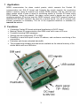
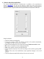
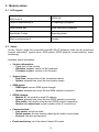
ecoLINE SIA IP Adapter INSTALLATION AND APPLICATION MANUAL for module version v2.25 and higher Rev. 1.5 21.06.2012 Table of contents 1 Application ........................................................................................................... 3 2 Functions ............................................................................................................. 3 3 Settings ................................................................................................................ 4 3.1 Configuring through USB connection........................................................... 4 3.1.1 GPRS settings .................................................................................. 4 3.1.2 SIA settings....................................................................................... 4 3.1.3 Automatic IP selection ...................................................................... 5 3.1.4 SIA user ID........................................................................................ 5 3.1.5 Dialed numbers for backup GSM call ............................................... 5 3.1.6 Modification of the settings by SMS.................................................. 5 3.1.7 Incoming SMS message forwarding ................................................. 5 3.2 Configuring by SMS commands................................................................... 6 4 Volume adjusting application ............................................................................... 8 5 Module status ...................................................................................................... 9 5.1 LED signals .................................................................................................. 9 5.2 Status ........................................................................................................... 9 6 Installation guide................................................................................................ 10 6.1 Mounting..................................................................................................... 10 6.2 Putting into operation ................................................................................. 10 7 Technical details ................................................................................................ 11 7.1 Technical specification ............................................................................... 11 7.2 Generated phone line specification............................................................ 11 7.3 Contents of the package ............................................................................ 11 2 1 Application GPRS communicator for alarm control panels, which converts the Contact ID communication into SIA IP format and forwards the events towards the monitoring station’s receiver using IP channel over mobile GPRS network. Can be used for any alarm system which is able to report to monitoring station in Contact ID format using PSTN landline. Using the adapter, the alarm control panel’s signals are sent to the monitoring station’s IP receiver over the GPRS network, using SIA IP protocol based on ANSI/SIA DC-09-2007 standard. No need for a central server, only an IP receiver with internet connection is necessary. The list of the supported receivers is available on www.tell.hu website. 2 Functions Converting Contact ID format and signal transferring in SIA IP format Backup Contact ID communication over GSM voice call in case of IP error Forwards incoming SMS messages Settings can be configured by PC or SMS Possibility to send test report to more IP address, and continuous monitoring of the connections Evaluates and shows estimated data traffic The programming software and manual are available on the internal memory of the device which acts as a USB drive 3 3 Settings 3.1 Configuring through USB connection The module acts as a standard USB drive among PC’s drives, and also creates a USB HID device. The programming software runs on the following operation systems: Windows XP SP2 Windows 7 Using the programming software („Drive letter”:\Software\Remoter\Remoter.exe) you can configure the parameters for the proper operation of the device. The following parameters can be configured in the programming software: 3.1.1 GPRS settings APN name: access point name for internet connection (provided by the GSM service provider) User and password: necessary only if required and provided by the GSM service provider The module restarts in every 3 minutes if the APN settings are wrong or missing! 3.1.2 SIA settings The module is able to forward the signals to 4 IP addresses, depending on the alarm control panel’s settings. The alarm control panel filters the events and forwards to the proper receiver. The module pairs the IP addresses with the dialed phone numbers by the alarm panel, then it converts the received events to IP-based format and transfers to the configured addresses. To check the continuous connections it is possible to enable test reports. Test reports can be enabled to all IP addresses independently from each other. The frequency of test reports can be configured in seconds. According to this parameter, an estimated traffic is calculated to check how much data traffic will be generated by the specified settings. Dialed number: when the alarm control panel dials the number entered here, the signals will be forwarded to the IP address entered in the corresponding “Remote IP address” field. The phone number set here must be exactly the same as the alarm panel dials, otherwise the module will not emit the handshake signal. Remote IP address: enter the IP address to where the signals should be forwarded when the alarm panel dials the phone number entered in the corresponding “Dialed number” field. Port: type the port number of the IP address which receives the forwarded signals. Test report frequency: enter the test report sending frequency in seconds. The module sends test report by this frequency to the corresponding IP address to check the availability. 4 Test report sending: if this option is enabled, the module will always check the IP connection using the configured test frequency. If this option is disabled, the module will check the specified IP address if it is absolutely necessary, that is the high priority IP addresses are not available. The highest priority IP address is checked automatically. Estimated data traffic: the estimated data traffic per month is displayed here, that depends on the configured test frequency. ATTENTION! THE DISPLAYED ESTIMATED DATA TRAFFIC IS CONSIDERED ONLY FOR THE TEST REPORTS, IT IS NOT IDENTICAL WITH THE MODULE’S ENTIRE MONTHLY DATA TRAFFIC! The SIA settings come into force after restarting the module. The module automatically restarts in every 24 hours. 3.1.3 Automatic IP selection When the alarm control panel dials this number, the events will be sent to the highest priority IP address currently available. The IP priorities correspond to the physical order of the IP addresses (SIA-IP1 to SIA-IP4). 3.1.4 SIA user ID Enter here the user ID programmed in the alarm control panel. In case of using more than one partition / user ID, then enter the first partition’s user ID. The module sends the GPRS/IP test reports using this user ID. The length of the SIA user ID can be minimum 1, maximum 6 characters. Do not fill the user ID with zeros! 3.1.5 Dialed numbers for backup GSM call If “GSM call filter” option is enabled, and the alarm control panel dials a phone number configured in the “Dialed numbers for backup GSM call” section, the module will initiate GSM call to the specified phone number. If this filter is not enabled, any phone number dialed by the alarm control panel which is not set in the module will initiate GSM call. Maximum 6 phone numbers can be set. 3.1.6 Modification of the settings by SMS A superuser phone number can be configured in this section, which is authorized to modify the settings by sending commands in SMS. The specification of the SMS commands can be found in “Configuring by SMS commands” chapter. 3.1.7 Incoming SMS message forwarding The module forwards incoming SMS messages to the phone numbers set here, which is useful for receiving SIM card balance information messages, etc. (if left blank, the module will delete all incoming SMS messages). Important! Do not set the phone number of the inserted SIM card here. 5 3.2 Configuring by SMS commands It is possible to configure the module and receive status information by sending the appropriate command in SMS to the module’s phone number. First set the SUPERUSER phone number from which the module will accept further SMS commands: SMS command Operation APN=APN name# The module sets the sender’s phone number as Superuser. The module accepts this parameter only if no Superuser has been set before! Deletes the current Superuser. The module accepts this command only from previously set Superuser phone number. Sets the APN name UN=APN user name# Sets the APN user name PW=APN password# Sets the APN password Setting the phone numbers assigned to IP addresses: substitute "X" with the ordinal number of the phone number to be set or modified. Setting the IP addresses: substitute "X" with the ordinal number of the IP address to be set or modified. Setting the port numbers: substitute "X" with the ordinal number of the IP address port number to be set or modified. Setting the test report assigned to IP addresses: substitute „X” and „Y” with the desired values: X= the ordinal number of IP address Y=0 (disabled) Y=1 (enabled) Setting the test frequency in seconds assigned to IP addresses: substitute "X" with the ordinal number of the IP address. Setting the phone number for the “Automatic IP selection” option. SUPERUSER# SU=# PHX=phone number# IPX=IP address# PORTX=port number# TESTX=Y# TSTFRX=frequency# AUTOIP=phone number# SELFID=SIA user ID# GSMS=Y# SPHX=phone number# SFW=phone number# FWVER?# Sets SIA user ID. Sets the „GSM call filter” option. Y=0 (disabled) Y=1 (enabled) Setting the backup phone numbers for GSM call: substitute "X" with the ordinal number of the monitoring station phone number to be set or modified, dialed for backup GSM call. Sets the phone number where incoming SMS messages will be forwarded. Querying the firmware version of module. 6 TROUT?# TRIN?# TRALL?# GMIC=X# GSPK=X# Querying “Outgoing data traffic” counter. The value is in the response message is specified in Bytes. Querying “Incoming data traffic” counter. The value in the response message is specified in Bytes. Querying “All data traffic” counter. The value in the response message is specified in Bytes. Adjusts the microphone volume (outgoing CID volume). Substitute X with a number between 0…15. Default setting: 3. Adjusts the speaker volume (incoming HSK/ACK volume). Substitute X with a number between 0…100. Default setting: 50. Commands must always end with hash "#" character. It is also possible to send more commands in one SMS, but the entire message must not exceed 160 characters. If the response SMS from the module would exceed 160 characters, only the first 160 characters are transferred. In case of making typing or command mistakes, the following response SMS will be received: "SYNTAX ERROR!" and the command(s) will not be executed. The module only accepts SMS commands sent from the Superuser phone number. Deleting settings: To delete a setting, do not enter any data after the equality sign. This can be applied for all data setting commands in the table above. Example: PH2=# : deletes the second phone number assigned to the second IP address IP3=# : deletes the third IP address SPH3=# : deletes the third backup GSM phone number SFW=# : deletes the SMS forward phone number Querying settings: For setting query use question mark after the command. This can be applied for all data setting commands in the table above. Example: PH2?# : querying the second phone number assigned to the second IP address IP3?# : querying the third IP address SPH3?# : querying the third backup GSM phone number SFW?# : querying the SMS forward phone number Examples for SMS command usage: To set the first monitoring station phone number (e.g. +3630123456789) assigned to the first IP address (e.g. 123.12.12.1) with port number (e.g. 9999), send the following SMS message to the module’s phone number: PH1=+36123456789#IP1=123.12.12.1#PORT1=9999# To erase a phone number set previously, leave the "phone number" part blank (e.g.: to erase the second monitoring station phone number, type: PH2=#). To request a previously set phone number, leave the “phone number” part blank and type “?” character without “=” character. (e.g.: to request the second monitoring station phone number, type: PH2?#). 7 4 Volume adjusting application The volume adjusting application (Volsetter.exe) is available on the manufacturer’s website (www.tell.hu). You can use this software to adjust the in-call volume levels if necessary and justified. Adjusting may be necessary if voice quality or volume problem is experienced while using the module with the given GSM service provider’s SIM card. Using the software: Start the Volsetter.exe application. Connect the module to USB. The software connects to the module automatically, then “Read” and “Set” buttons become available. Read the actual settings from the module by pressing “Read from module” button. Mic volume: microphone volume (outgoing Contact-ID). Spk volume: speaker volume (incoming HSK/ACK). Set the desired volume level, then write the settings to the module by pressing “Set” button. Attention! Even minor level modifications cause significant changes in the in-call volume! The new settings are applied after writing in the very next voice call. 8 5 Module status 5.1 LED signals Green blinks slowly, Red is not lit GPRS OK Green is continuously lit IP reporting in progress Green blinks fast GSM reporting in progress Red blinks 3 times Reporting failed Red is continuously lit Trouble 5.2 Status On the “Status” page the connected ecoLINE SIA IP Adapter’s state can be monitored (version information, system timer, GSM status, GPRS network, communication, event monitoring). Available status information: Version information: - Type: type of the module - Hardware version: version of the hardware - Firmware version: version of the firmware System timer: - Date/time: internal clock of the connected module - Uptime: elapsed time since the last module restart GSM status: - GSM signal: current GSM signal strength - Uptime: elapsed time since the last GSM network connection GPRS network: - Module IP: the module’s actual IP address - Uptime: elapsed time since the last GPRS network connection - Data traffic: data traffic since the last GPRS network connection - Number of connections: actual number of the IP connections Communication: - Line status: actual line state - Dialed number: the last number dialed by the alarm control panel - Protocol: the last used protocol Event monitoring: list of the latest Contact ID events 9 6 Installation guide 6.1 Mounting Test the GSM signal strength with your mobile phone and then repeat this using the module after the installation. It may happen that the signal strength is not sufficient in the desired mounting place. In this case the planned installation place can be changed before mounting the device. Do not mount the unit in places where it can be affected by strong electromagnetic disturbances (e.g. in the vicinity of electric motors, etc.). Do not mount the unit in wet places or places with high degree of humidity. Connecting the GSM antenna: the antenna can be connected to the FME-M connector. The antenna supplied with the module provides good transmission under normal reception circumstances. In case of occasionally occurring signal strength problems or/and wave interference (fading), use another (directed) type of antenna or find a more suitable place for the module. 6.2 Putting into operation Disable PIN code request and voicemail on the SIM card placed into the module. Enable caller identification and caller ID sending services on the SIM card at the GSM service provider (on a few types of SIM cards these services are not enabled by default). Enable the mobile data traffic package at the GSM service provider Place the SIM card into the case according to the sticker on the module. If you want to remove the SIM card just push the card again. Check the antenna to be fixed properly to the ecoLINE module. The device can be powered up. Make sure that power supply is sufficient for the load of the module. The quiescent current of the module is 110mA, however it can reach up to 400mA during communication. 10 7 Technical details 7.1 Technical specification Supply voltage: Nominal current consumption: Maximum current consumption: Operating temperature: Transmission frequency: GSM phone type: Dimensions: Weight: 9-30 VDC 110mA @ 12VDC, 60mA @ 24VDC 400mA @ 12VDC, 200mA @ 24VDC -20ºC - +70ºC GSM 900/1800 MHz, 850/1900 MHz Simcom SIM900 100 x 70 x 19mm 80g (packed: 100g) 7.2 Generated phone line specification Line voltage: Line current: Line impedance: Ring voltage: Tone: 48 V 20 mA 600 Ohm ±72V (25 Hz) 400 Hz 7.3 Contents of the package ECOLINE SIA IP module GSM 900/1800 MHz antenna Plastic spacer User manual USB cable Warranty card 11