1
JT600 User Manual
Ver 1.5
11-15-2011
-1-
Content
JT600 User Manual ............................................................................................................................................................................................ - 1 Content ................................................................................................................................................................................................................... - 2 ⅠPreface ............................................................................................................................................................................................................... - 4 Ⅱ Updates ............................................................................................................................................................................................................ - 4 Ⅲ Product Function ......................................................................................................................................................................................... - 5 Ⅳ Profile and Description.............................................................................................................................................................................. - 6 4.1 Profile ......................................................................................................................................................................................................... - 6 4.2 Operation Button ................................................................................................................................................................................... - 7 4.3 Working mode ........................................................................................................................................................................................ - 8 4.4 Voice communication .......................................................................................................................................................................... - 9 Ⅴ First Use ........................................................................................................................................................................................................... - 9 5.1
Install SIM card ................................................................................................................................................................................ - 10 -
5.2
Charging ............................................................................................................................................................................................. - 10 -
5.3
LED Indications ............................................................................................................................................................................... - 10 -
5.4
Configure by PC setup software................................................................................................................................................ - 11 -
5.4.1 PC setup Software Introductions ......................................................................................................................................... - 11 5.4.1.1 Main Settings......................................................................................................................................................... - 11 5.4.1.2 Authorization Number ...................................................................................................................................... - 19 5.4.1.3 Geo-fence Setting ................................................................................................................................................ - 21 5.4.1.4 Advanced Operations ........................................................................................................................................ - 25 5.5
Location Short Message format ................................................................................................................................................ - 27 -
5.6
Configure by SMS ............................................................................................................................................................................ - 28 -
-2-
5.6.1 SMS Command Framework and List .................................................................................................................................. - 28 5.6.2 Short Message Command Example..................................................................................................................................... - 31 Ⅵ Product Specification .............................................................................................................................................................................. - 35 6.1 Physical Parameters and Environmental ................................................................................................................................. - 35 6.2 GPS module parameter .................................................................................................................................................................... - 36 6.3 GSM module parameter ................................................................................................................................................................... - 37 Ⅶ Standard package and optional accessories .................................................................................................................................. - 39 Ⅷ FAQ ................................................................................................................................................................................................................. - 40 Ⅸ SAR .................................................................................................................................................................................................................. - 40 -
-3-
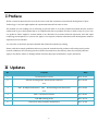
ⅠPreface
All the content in this manual is accurate, however, with the continuous research and development of Joint
Technology Co.,Ltd, we might update the operational manual from time to time.
The manual you are reading now is reflecting of present state of art of the products described therein, we have
endeavored to give a description that is as complete and clear as possible in order to make it easy for you to use
our products. There might be content which is not described in accurate technical expression, with the rapid
technology development, we reserve the rights to incorporate technical alterations and developments without
separate notice in advance.
You can refer to the latest operation manual and relative documents by visiting
Please read those simple guidelines before use, Jointech assured that the products will work properly under
normal conditions, the warranty period would be 12 months from the delivery date, the warranty shall not
apply to any defect, failure or damage which caused by improper maintenance, repair, alteration.
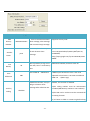
Ⅱ Updates
No.
Content
Date
1
Documentation release
2010-12-22
2
Edit the working mode, Add P14,P18 command
2011-02-26
V1.1
3
Edit
4.2 Operation Button
and
4.3 working mode instruction
2011-04-26
V1.2
4
Edit 5.1 PC based software
2011-08-05
5
Edit 4.3 working mode
2011-10-19
6
Edit 5.4 PC Setup software introduction
2011-11-24
-4-
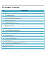
Ⅲ Product Function
No.
Product Function
1
Data transmission mode(SMS/TCP)
2
Track by SMS/GPRS
3
Track by time interval
4
Track by Calling(reply a location short message to mobile phone)
5
Base station Location (CELL ID and LAC)
6
Two-way voice function
7
Automatic answer the call
8
Listen-in function(Voice monitoring)
9
64 Geo-fence support
10
Self Geo-fence(User defined Geo-fence)
11
Real-time power monitoring
12
GSM and GPS signal strength detecting
13
Support remote/PC setup setting
14
Low Battery alert, SOS alert, Geo-fence alert
15
Solar power charger
16
Inbuilt battery 1800mAh
17
Solar power working indication
18
flashlight function
19
Mini-USB port, cable(charging, upgrading, configuration)
20
Up to 2 months working(Timing mode)
21
Vibration detecting
22
RTC
23
Factory reset
-5-
Ⅳ Profile and Description
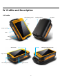
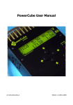
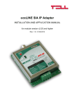
4.1 Profile
Solar battery panel
Backup battery
Arc Hook
Panel
Power on/off
CALL Ⅰ
CALL Ⅱ
Water-proof
Mic
strip
Flashlight /indication LED
SOS button
Open it here
Mini USB power/data
SIM card Slot
槽
-6-
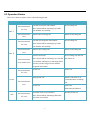
4.2 Operation Button
There are 4 buttons, please refer to the following details:
Button
Operation
Press this button
CALL Ⅰ
for 3 sec
Press this button
Function
Call the first preset VIP number .
Conditions
No incoming call
Note: JT600 will be vibrating if you dial
this number successfully.
Answer the incoming call
When an incoming call
Call the second preset VIP number.
No incoming call
once
Press this button
for 3 sec
Press this button
CALL Ⅱ
Note: JT600 will be vibrating if you dial
this number successfully.
Answer the coming call
When an incoming call
Self Geo-fence ON
No incoming call. and self
Note: JT600 will be vibrating if you set this
Geo-fence off
once
Press this button
twice within 3sec
successfully. and there is a message which
informs you the self geo-fence latitude,
longitude and radius .
Press this button
Power off.
Power on
Hang up the call
When a call come or in
for 3 sec
Power
communication or Dialing
Press this button
once
out
Power On
Power off
And inserted SIM card
SOS
Press this button
for 3 sec
Send SOS alert to VIP numbers
Note: JT600 will be vibrating if SOS alert
was sent successfully.
-7-
Normal. Power on
press the SOS button once, the LED
Normal. Power on
indication of SOS would be changed in
turn, as below:
Press this button
once
On: flashlight
Flash: the led would flash according to the
international SOS standard
Off: SOS led is off
(Table 1)
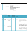
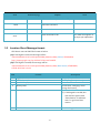
4.3 Working mode
No.
Working mode
Wakeup
GSM Module
condition
while sleeping
GPS Module
while
Note
sleeping
both GSM and GPS module work
Press any
1
Standard
button/coming
properly, the device can be used
Sleep
Power on
call/SMS
to call and receive incoming call,
send and receive text messages at
any time.
Preset the time point, the device
will wake automatically at this
preset time, and works for 10
minutes before getting into the
2
Timing
Data upload
interval timer
sleep mode. The device supports
Power off
Power off
48 time points in maximum, but
the interval between each two
points
should
be
above
30
minutes. GSM and GPS module
work properly at the working
period, and both are closed in the
-8-
sleeping period. The device works
only 10 minutes in every awaken,
so the interval for data uploading
should be set less than 10
minutes,
otherwise
the
data
cannot be uploaded properly.
Vibration awaken, the device will
go to sleep in 10 minutes from
last vibration. Both GSM and GPS
module
works
properly
in
working period, but both are
3
Vibration
Vibrating
Power off
Power off
closed in sleeping period. The
device works only 10 minutes in
every awaken, so the interval for
data uploading should be set less
than 10 minutes, otherwise the
data
cannot
be
properly.
(Table 2)
4.4 Voice communication
JT600 has the two-way voice function, It can dial preset phone numbers and receive phone call as
well. When a call coming, the unit will ring, press CALL Ⅰbutton once to receive the call.
Press CALL Ⅰ or CALL Ⅱ button for 3 seconds to call the preset VIP number.
The phone call can also be hung up by pressing power button once.
Ⅴ First Use
-9-
uploaded
5.1 Install SIM card
Make sure the SIM Card has been activated GPRS internet access and SMS function. You can check it in your
mobile phone.
Plug the SIM card into SIM Card slot and Power on JT600.
5.2 Charging
Normally, you need Charge it about 5 hours. The “CH” LED will turn green when charged enough.
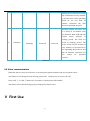
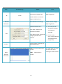
5.3
LED Indications
LED
CH LED(RED)
POW LED
(yellow)
GSM
LED(Green)
Status
On
Charging
Turn Green
The battery is full
Off
No charging
Blinking
Low Battery. You need to charge the unit.
Blinking every 5 seconds
JT600 got GSM signal.
Blinking every 1 seconds
JT600 didn’t get GSM signal Or Didn’t plug SIM card
Blinking 10 times in one
second(Very fast)
GPS LED(Blue)
Flashlight
Note
GPRS connected, Data uploading to center server.
Blinking every 10 seconds
GPS signal is valid
Blinking every 3 seconds
GPS signal is invalid
Off
GPS module Power off
On
Flashlight
- 10 -
LED(White)
Thrice long and short
SOS
circulating continuously
Off
Note:
Normal
All LEDs will be off if the tracker goes to sleep mode.
(Table 3)
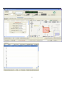
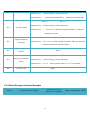
5.4
Configure by PC setup software
Refer to the manual《JT600 Mini-USB Cable Driver InstallationV1.2.pdf》,Install the Mini-USB cable driver, and
plug it to PC. Copy “JT600 Assistant V3.0” software to your PC and Open it.
Note:
If you open this software in Win 7 system, Please right click its ICON, and Click “Run as administrator”, Or
This software won’t show the COM port number.
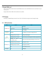
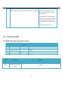
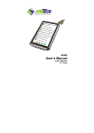
5.4.1 PC setup Software Introductions
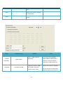
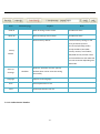
5.4.1.1 Main Settings
- 11 -
Name
Parameter
Explain
Get The COM port number after
Com Port
3
plugged the Configuration cable
Note
Refer to the manual《JT600
Mini-USB Cable Driver
InstallationV1.2.pdf》
Baud Rate
9600
Open/Close
Open/Close
Fixed value
Click it, and Connect to PC
- 12 -
Click it ,Pop-up a window shows all
Debug Info
Item
commands reply message
Parameter(e.g.)
Explain
Click it, and Get all Basic
information
Another
Name
ID
jeson
3100513059
You need to set the Another name
firstly. Or it shows blank
10 digit numbers. It’s the unique ID
of this unit
GSM
Indicates GSM signal Strength
GPS
Indicates GPS signal Strength
Battery
Version
Indicates Charging status of Battery
20111123
Firmware version
- 13 -
Note
Item
Parameter(e.g.)
SMS
Primary
Explain
Note
Set it to receive all location
+8615017343411
Number
short message ,alert message
and command reply message.
Set it to replace the unique ID
Another
Name
Supports country code
of each location short
jeson
message.
jeson,09-28
12:11:02,Speed:32km/h,Battery:80%,GPS:13,
STANDARD,
http://maps.google.com/?q=22.549737N,114.07
6685E
Low
Battery
Time
difference
when the battery charge is low
20
than 20%, there is a low battery
alert.
China GMT+8. 480minutes
480
GMT use
will get a location short
Calling
JT600 outputs Greenwich time. It has to be
adjusted to local time. To set time zone behind
Enable this function, and you
Track by
Maximum value 90, minimum value 10.
message after called the unit.
checkbox
–(Minus sign)
Default, This function is disabled.
1)The calling number must be authorization
numbers(SMS Primary number or VIP numbers).
2)The SIM card in tracker must be activated call
screening function.
3) It’s better to hold on 2 times ring before hang
- 14 -
up.
Enable this function, And
Automatic
answer the
JT600 will answer the coming
checkbox
call automatically after ring 3
call
times.
Read
Read current tracker’s settings
for above items.
White
Write above settings to the
tracker.
Item
Parameter(e.g.)
Ip address
123.123.123.123
Port
8888
APN
CMNET
APN user
APN pass
Default, This function is disabled.
1)The SIM card in tracker must be activated call
screening function.
Explain
Note
Server IP address or Domain
name
TCP port
China mobile GPRS access point
name. CMNET
No need set it if the APN user is
blank.
No need set it if the APN pass is
- 15 -
Please ask the GPRS service
provider
blank.
Read
Read current tracker’s settings
for above items.
White
Write above settings to the
tracker.
Item
Normal
Uploading
Parameter(e.g.)
Radio button
Explain
Note
Click it ,enable “Normal
If you choose this Uploading
Uploading”
mode,JT600 will upload data as
preset time interval and data
transmission mode all the time.
enable this function,JT600
Keep Alive
Checkbox and 300
will upload a keep alive
report to center server
- 16 -
Default, This function is disabled.
The unit can be set to send short
keep alive report to the server to
every 300 seconds.
Note:
If the data uploading
prevent the disconnection from the
mobile service provider. Some GSM
provider might cut connection if
there is no data within certain time.
interval is more than the
time that GSM provider cut
GPRS connection. You must
enable the Keep alive
function. Or you can’t
control JT600 by server.
enable “Uploading by
Vibration awaken, the device will go
Vibration”
to sleep in 10 minutes from last
vibration. Both GSM and GPS
module works properly in working
Uploading
by Vibration
period, but both are closed in
Radio button
sleeping period. The device works
only 10 minutes in every awaken, so
the interval for data uploading
should be set less than 10 minutes,
otherwise the data cannot be
uploaded properly.
Fixed time
point
enable “Fixed time point
Preset the time point, the device will
uploading” And Click the
wake automatically at this preset
time label to choose the
time, and works for 10 minutes
time points.
before getting into the sleep mode.
Radio button
Jt600 will wake up when the
time at 8:00,9:00,12:00,
uploading
14:00,18:30,19:30.
The device supports 48 time points
in maximum, but the interval
between each two points should be
above 30 minutes. GSM and GPS
module work properly at the
Note:
1)You need adjust the time
working period, and both are closed
in the sleeping period. The device
works only 10 minutes in every
- 17 -
difference to local time.
2)JT600 must locate
position at the first time.
Data transmission mode
SMS
awaken, so the interval for data
uploading should be set less than 10
minutes, otherwise the data cannot
be uploaded properly.
Uploading location Short message to
SMS primary number.
SMS
Mode
Data transmission mode
TCP
Uploading GPS data to Server IP
address and TCP Port
GPRS
150 seconds
Please refer to Section 2.4.4 P04
Enquire or Set Data uploading
Interval
150
SMS
[150,65535]
TCP
[5,65535]
=0,Uploading data all the
time.
Times
Uploading all the time
=[1,65535] It will stop
uploading when reaching
preset times.
Read
Read current tracker’s
settings for above items.
White
Write above settings to the
tracker.
- 18 -
interval. <JT600 protocol>
Item
Parameter(e.g.)
Explain
Note
Read All
Read all settings of the tracker
Exclude Geo-fence
Write All
Write all settings of the tracker
Exclude Geo-fence
Restore factory default
Restore factory settings. It will
clear parameters(such as
Geo-fence/Uploading mode)
except IP address,Port,SMS
Factory
Primary number, VIP numbers,
Default
APN,APN account,Another name
and time difference.and JT600 will
be reset to Normal Uploading and
SMS mode.
Show tip
message
show the “operation success” pop-up
checkbox
window when read or write the setting
successfully.
Language
Supports multi-language
Save
Save all parameters to PC
Load
Load all parameters from PC
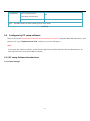
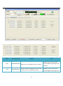
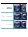
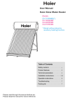
5.4.1.2 Authorization Number
- 19 -
Item
Parameter(e.g.)
Explain
Set the first VIP number. Press the CALL Ⅰ
Call 1
Call 2
+8615017924411
+8613017924411
Button for 3 sec,JT600 will call this number.
Note
Supports country code. And It
receives SMS reply message, alert
message.
Set the second VIP number. Press the CALL
Supports country code. And It
Ⅱ Button
receives SMS reply message, alert
for 3 sec,JT600 will call this
- 20 -
3
number.
message.
VIP number 3
Supports country code. And It
+8615017924413
receives SMS reply message, alert
message.
VIP number 4
4
Supports country code. And It
+8615017924414
receives SMS reply message, alert
message.
VIP number 5
5
Supports country code. And It
+8615017924415
receives SMS reply message, alert
message.
Geo fence
alarm
Self Geo-fence
alarm
checkbox
Choose it, So the corresponding VIP number
can receive this alert message.
User entered into or exited the
preset Geo-fence ,there would be
a Geo-fence alarm.
checkbox
Choose it, So the corresponding VIP number
can receive this alert message
Press the CALL
Ⅱ
Button twice
within 3 seconds to set self
Geo-fence.
SOS alarm
checkbox
Choose it, So the corresponding VIP number
can receive this alert message
Battery alarm
checkbox
Choose it, So the corresponding VIP number
can receive this alert message
Read
Read current tracker’s settings for above
items.
White
Write above settings to the tracker.
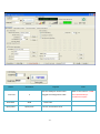
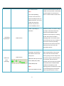
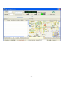
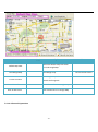
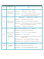
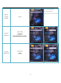
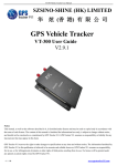
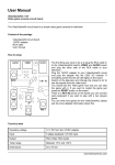
5.4.1.3 Geo-fence Setting
- 21 -
Low Battery alarm.
- 22 -
- 23 -
Item
ID
Parameter(e.g.)
Explain
Note
Click this record and Get the
Please Load the Google
Geo-Fence on Google map.
Map at right side.
1 to 64
Double Click this record and
begin to edit this fence.
Read All
Read all Geo-fence settings
Geo-fence
Map at right side.
Edit selected Geo-fence
Click “Save” button to set
Geo-fence to tracker.
Edit
Please Load the Google
Click “Close” button: Cancel the
changing and Close this
window.
1) You can input the
Geo-fence’s latitude
and longitude
manually.
2) Click the map
twice ,and Get latitude
and longitude from
Google map.
Disable
Write
selected
Click this button to disable the
selected Geo-fence.
‘CTRL +A ‘ ,you can choose all
It’s useful when you need
records.
the same Geo-fence
‘Shift’ choose some of
records.
Geo-fence
- 24 -
setting for another tracker.
Item
Parameter(e.g.)
Default Map View
Load Google Map
Current Location
Explain
Note
Define the default map view when
you load Google Map
Load Google map
Click Google Map and Get current
latitude and longitude
Show All Geo-fence
Show All Geo-fence on Google Map
Clear All Geo-fence
Clear All Geo-fence on Google Map
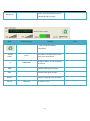
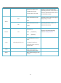
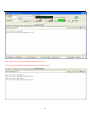
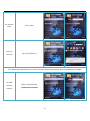
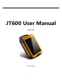
5.4.1.4 Advanced Operations
- 25 -
PC has internet access.
The Interface for people who know JT600 protocol well.
You can send any ASCII command in protocol on this interface.
- 26 -
Item
Parameter(e.g.)
ASCII command
Note
Please read JT600 protocol carefully.
Send
Send this command
Clear
Clear the below commands records
Save all records to PC
Save
5.5
Explain
It’s useful for engineer to
analysis your Operations.
Location Short Message format
GPS data is sent via SMS. The format as below:
(A) If GPS signal is valid, the message will be:
3101223002,09-28 12:11:02,Speed:32km/h,Battery:80%,GPS:13, STANDARD,
http://maps.google.com/?q=22.549737N,114.076685E
(B) If GPS signal is invalid, the message will be :
3101223002,09-28 12:11:02,Speed:32km/h,Battery:80%,Base Station, STANDARD,
Cell ID:4232,LAC: 10133
Item
Content
1
2
3
4
e.g”John”or 3101223002..etc
09-28 12:11:02
Speed:32km/h,
Battery:80%
5
GPS:13,
6
STANDARD
Description
Unique ID or Another name
Month/Day/hour/minute/second
It will show “Charging” when
charge the battery.
1) Number of satellites received;
2) If GPS signal is invalid, this
item will be replace with
“Base Station”. It indicates
item 7 is got from Base
station.
Working mode
- 27 -
7
1)If GPS signal is valid,JT600
http://maps.google.com/?q=22.549737N,114.076685E repies a Google map link. Click
this link to view fix location via
mobile phone;
e.g:
2)If GPS signal is invalid, JT600
repies CELL ID and LAC. CELL ID
and LAC are got from Base station
and showed in decimal system.
e.g
Cell ID:4232,LAC: 10133
5.6
Configure by SMS
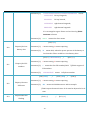
5.6.1 SMS Command Framework and List
No.
1
2
3
4
5
Command
Code
P01
name
Packet head
command
separative sign
parameter
Packet end
Length
(bytes)
1
3
1
N
1
Note
Fixed "("
Such as P03 ect…
“,”mark
"," to separate the various parameters
)
Description
Example
Enquire the firmware
(P01)
version
- 28 -
P02
Enquire current
(P02)
position
(P03,1,13919192020) /
P03
Enquire/Set SMS
Primary number
Parameter[1]:
1 means setting ,0 means
(P03,0)
enquiring
Parameter[2]: 13919192020 means SMS center number. Don’t be more
than 15 digital numbers. Supports country code.
(P04,1,60,2,1)
/
(P04,1,150,0,0) /
(P04,0)
Parameter[1]: 1 means setting, 0 means enquiring
P04
Enquire/Set Data
uploading interval
Parameter[2]: 60 means 60 seconds ,uploading every 60 seconds
Parameter[3]: 2 means uploading 2 times and then stops uploading data.
If you input 0 ,It will upload data all the time.
Parameter[4]:1
1 indicates TCP ,0 indicates SMS
(P05,1,211.154.134.212,8000,CMNET,,)
/
(P05,0)
Parameter[1]: 1 means setting, 0 means enquiring
Enquire/Set GPRS
P05
network
parameters(IP
address, Port)
Parameter[2]: 211.154.134.212 means Server IP address
Parameter[3]:
8000 means TCP port
Parameter[4]: CMNET means APN name .access point name at local. CMNET
is example in china.
Parameter[5]: APN user APN username. If it’s blank. no need input it.
Parameter[6]: APN pass APN password. If it’s blank. no need input it.
(P08,1,1,11323.1234,2312.2321,11326.4312,2308.1233,area 1)
P08
Enquire/Set
Geo-fence
Parameter[1]: 1 means setting, 0 means enquiring
Parameter[2]: 1 means Geo-fence ID.JT600 supports 64 fences.
- 29 -
Parameter[3]:
11323.1234,2312.2321,11326.4312,2308.1233 means
11323.1234 left top longitude,
2312.2321
left top latitude,
11326.4312 right bottom longitude,
2308.1233
right bottom longitude.
It’s a rectangular region. Please set Geo-fence by JT600
Assistant software.
Parameter[4]: area 1 means Geo-fence name.
(P10,1,20)
P10
Enquire/Set Low
battery alert
Parameter[1]: 1 means setting, 0 means enquiring
Parameter[2]: 20 means 20%. when the power percent of the battery is
low than this. There would be a Low Battery alert.
(P11,1,1,13910102345)
/
(P11,0,5)
Parameter[1]: 1 means setting, 0 means enquiring
P11
Enquire/Set VIP
numbers
Parameter[2]: 1 means the first VIP number(CALL Ⅰ).JT600 supports 5
VIP numbers.
Parameter[3]:
13910102345 means Cell phone number
(P12,1,480)
/
(P12,0,480) /
(P12,0)
Parameter[1]: 1 means setting, 0 means enquiring
P12
Enquire/Set time
difference
Parameter[2]: 480 means 60*8=480 minutes. 480 is example.
JT600 outputs Greenwich time. So It must be adjusted to local
time.
P13
Require SOS LED
flashing
(P13,1,1)
- 30 -
/
(P13,1,0)
Parameter[1]: 1 means setting, 0 means enquiring
Parameter[2]: 1 means open the SOS LED .0 means close the SOS LED.
(P14,1,5)
/ (P14,0,5)
Parameter[1]: 1 means setting, 0 means enquiring
P14
Set ring volume
Parameter[2]: 5
from 1 to 7. 1 indicates minimum volume. 7 indicates
maximum volume.
(P15,13919192020)
P15
Require Listen-in
remotely
Parameter[1]: 13919192020 means cell phone number. After you send this
command ,JT600 will call this number.
P16
Enquire current
(P16)
battery
(P17,1,jointech)
P17
Enquire/Set another
name
Parameter[1]: 1 means setting, 0 means enquiring
Parameter[2]: jointech means another name. jointech is a example.
P20
Factory reset
(P20)
5.6.2 Short Message Command Example
Feature
Command format example
Send Short message
command via cell phone
- 31 -
Reply message from JT600
Set SMS
Primary
number
(P03,1,13504562154)
// SMS Primary number
Set
CALLⅠnumb
(P11,1,1,15017935411)
er
Set CALL Ⅱ
number
(P11,1,2,15014059956)
- 32 -
John ,09-28 12:11:02,Speed:32km/h,
Battery:80%,GPS:13,STANDARD,
http://maps.google.com/?q=22.549737N,114.0766
Enquire
current
85E
(P02)
position
Set time
difference
(P12,1,480)
//GMT +8
8*60=480 minutes in china
Set Low
(P10,1,20)
battery alert
//20%
- 33 -
Set Another
name
Listen-in
remotely
(P17,1,John)
(P15,15017935411)
The following commands are used for real-time monitoring setting. Data transmission via GPRS.
Set SMS
Primary
number
(P03,1,13504562154)
// SMS Primary number
- 34 -
Set working
(P07,1,1)
mode
//Standard mode
(P07,1)
(30000000001,P05,211.154.136.219,8888,cmne
(P05,1,211.154.136.219,8888,cmnet,
t,,)
,)
//cmnet
Set IP address
and APN
parameter
GPRS APN in china
The whole command:
(P05,1,211.154.136.219,8888,APN,A
PN user,APN pass)
Set Data
uploading
interval for
(30000000001,P04,60,0,1)
(P04,1,60,0,1)
//upload GPS data every 60 seconds
continuously
SMS or GPRS
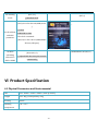
Ⅵ Product Specification
6.1 Physical Parameters and Environmental
size
unit : 96mm * 51mm * 22mm , bake up battery
weight
unit : 80g , backup battery: 50g
housing
plastic
Working
-25~+70℃
temperature
- 35 -
Inbuilt Battery
1800mAh
Back-up battery
2500mAh
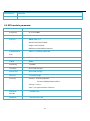
6.2 GPS module parameter
Chipset
SiRF Star III
Frequency
L1,1575.42MHz
Code
C/A Code
Protocol
NMEA 0183 V2.2
Default:GGA,GSA,GSV,RMC
Support:VTG,GLL,ZDA
SiRF binary and NMEA Command
Available Baud
4,800 to 57,600 bps adjustable
Rate
Channels
20
FLASH
4Mbits
Sensitivity
-159dBm
Cold start
42 seconds,average
Worm start
38 seconds,average
Hot start
1 second,average
Accuracy
Position : 10 meters,2D RMS
5 meters,2DRMS,WAAS enabled
Velocity : 0.1m/s
Time : 1us synchronized to GPS time
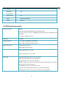
Maximum
< 18,000 meter
Altitude
Maximum
< 515 meter/second
- 36 -
Velocity
Maximum
< 4G
Acceleration
Update Rate
1Hz
DGPS
WAAS,EGNOS,MSAS
Datum
WGS-84
6.3 GSM module parameter
Frequency bands
SIM900
Quad-band: GMS 850,EGSM 900,DCS 1800,PCS 1900.
The band can be set by AT COMMAND, and default band is EGSM 900 and
DCS 1800.
Compliant to GSM Phase 2/2+.
GSM class
Small MS
Transmit power
Class 4(2W) at EGSM900 and GSM850
Class 1(1W) at DCS1800 and PCS 1900
GPRS connectivity
GPRS multi-slot class 10
GPRS mobile station class B
Temperature range
Normal operation : -20~+55℃
Restricted operation : -25~+70℃
Data GPRS
GPRS data downlink transfer: max. 85.6 kbps
GPRS data uplink transfer: max. 42.8 kbps
Coding scheme: CS-1, CS-2, CS-3 and CS-4
SIM900 supports the protocols PAP (Password Authentication Protocol)
usually used for PPP connections.
The SIM900 integrates the TCP/IP protocol.
Support Packet Switched Broadcast Control Channel (PBCCH)
CSD transmission rates: 2.4, 4.8, 9.6, 14.4 kbps, non-transparent
- 37 -
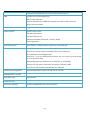
Unstructured Supplementary Services Data (USSD) support
SMS
MT, MO, CB, Text and PDU mode
SMS storage: SIM card
Support transmission of SMS alternatively over CSD or GPRS. User can
choose preferred mode.
SIM interface
Supported SIM card: 1.8V ,3V
Audio features
Speech codec modes:
Half Rate (ETS 06.20)
Full Rate (ETS 06.10)
Enhanced Full Rate (ETS 06.50 / 06.60 / 06.80)
Echo suppression
External antenna
Connected via 50 Ohm antenna connector or antenna pad.
Two serial interfaces
Serial Port 1 Seven lines on Serial Port Interface
Serial Port 1 can be used for CSD FAX, GPRS service and send
AT command of controlling module.
Serial Port 1 can use multiplexing function, but you can not use the Serial
Port 2 at the same time;
Autobauding supports baud rate from 1200 bps to 115200bps.
Serial port 2 Two lines on Serial Port Interface /TXD and /RXD
Serial Port 2 only used for transmitting AT command.
Phonebook management
Supported phonebook types: SM, FD, LD, RC, ON, MC
SIM Application Toolkit
Supports SAT class 3, GSM 11.14 Release 98
Real time clock
Implemented
Timer function
Programmable via AT command
Firmware upgrade
Firmware upgradeable over serial interface
- 38 -
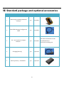
Ⅶ Standard package and optional accessories
Item
1
2
3
4
5
Accessories name
Main body( including 1800mAh
battery)
Mini-USB charging/configuration
cable
CD(user manual/ configure
software)
Charging(directly)
Back-up battery(2500mAh)
Unit
Explain
pcs
Standard
pcs
Standard
Accessories picture
The latest information can be
pcs
Standard
downloaded from
www.joint-tracking.com
pcs
Optional
pcs
Optional
- 39 -
6
Upgrade cable
pcs
Optional
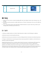
Ⅷ FAQ
1. Default, The unit works at Normal uploading SMS mode and Uploads location short message every 150
seconds.
2. The unit can only be powered on whiles SIM card put in. The unit will powered off as soon as the SIM card
pulled out.
3. If you connected the upgrade cable with JT600,It would be shutdown. To power on the unit, you have to pull
and plug SIM card and press power button once.
Ⅸ SAR
1. This device complies with Part 15 of the FCC Rules. Operation is subject to the following two conditions:
(1) This device may not cause harmful interference.
(2) This device must accept any interference received, including interference that may cause undesired operation.
2. Changes or modifications not expressly approved by the party responsible for compliance could void the user's
authority to operate the equipment.
Designed and manufactured not to exceed the emission limits for exposure to radiofrequency (RF) energy set by
the Federal Communications Commission of the U.S. Government.These limits are part of comprehensive
guidelines and establish permitted levels of RF energy for the general population. The guidelines are based on
standards that were developed by independent scientific organizations through periodic and thorough evaluation
of scientific studies. The standards include a substantial safety margin designed to assure the safety of all
- 40 -
persons,regardless of age and health. The exposure of measurement known as the Specific Absorption Rate, or SAR.
The SAR limit set by the FCC is 1.6W/kg and the CE is 2.0 W/kg. transmitting at its highest certified power level in
all Your Portable GPS Tracker is a radio transmitter and receiver. It is at the highest certified power level, the well
below the maximum value. This is power levels so as to use only the power required to reach the network. In
general, the closer you are to a wireless base station antenna, the available for sale to the public, it must be tested
and certified to the FCC that it does not exceed the limit established by the government adopted requirement for
safe exposure. The tests are performed in positions and locations (e.g., at the ear and worn on the body) as
required by the FCC for each model. The FCC has granted an Equipment Authorization for evaluated as in
compliance with the FCC RF exposure guidelines. SAR information on this model the Display Grant section of
http://www.fcc.gov/ oet/fccid after searching on FCC ID: ZO8JT600.
- 41 -