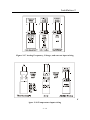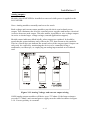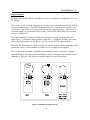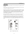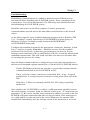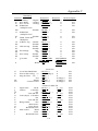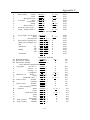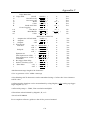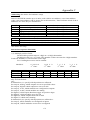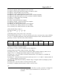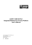
1
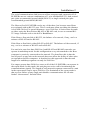
-i-
I/O PLEXER
Nov. 23, 2004
Copyright
Copyright 2004-duTec inc. All rights reserved. However, any part of
this document may be reproduced, provided that duTec inc. is cited as
the source. The contents of this manual and the specifications herein
may change without notice.
Trademarks
The duTec logo and I/O PLEXER are trademarks of duTec inc.
WINDOWS™ and WINDOWS 95 are trademarks of MicroSoft.
Notice to the User
The information contained in this manual is believed to be correct.
However duTec inc. assumes no responsibility for any of the circuits
described herein, conveys no license under any patent or other right
and makes no representations that the circuits are free from patent
infringement. duTec inc. makes no representation or warranty that such
applications will be suitable the use specified without further testing or
modification.
DuTec inc. general policy does not recommend the use of its products
in life support applications where failure or malfunction of a
component may directly threaten life or injury. It is a condition of sale
that the user of duTec inc. products in life support applications assumes
all risk of such use and indemnifies duTec inc. against all damage.
Warranty
duTec inc. warrants its products to be free of defects in materials and
workmanship for a period of two (2) years from the shipment date.
DuTec inc., at its option, will repair or replace all material found to be
defective. All repair or replacement must be performed by duTec inc.
personnel. Any parts determined by duTec inc. to be defective as a
result of abuse, misuse or attempts to repair will be repaired at the
expense of the customer. DuTec inc. will not be held liable for any
consequential, incidental, or special damages.
-ii-
Table of Contents
Overview . . . . . . . . . . . . . . . . . . . . . . . . . . . . . . . . . . . . . . . . . . . . . . . . . . . .
Capacity: . . . . . . . . . . . . . . . . . . . . . . . . . . . . . . . . . . . . . . . . . . . .
I/O Signal Compatibility . . . . . . . . . . . . . . . . . . . . . . . . . . . . . . . .
Built-in Diagnostics: . . . . . . . . . . . . . . . . . . . . . . . . . . . . . . . . . . . .
Easy Setup: . . . . . . . . . . . . . . . . . . . . . . . . . . . . . . . . . . . . . . . . . . .
Protocol Compatibility . . . . . . . . . . . . . . . . . . . . . . . . . . . . . . . . . .
1-1
1-1
1-2
1-2
1-3
1-3
Available I/O Functionality: . . . . . . . . . . . . . . . . . . . . . . . . . . . . . . . . . . . . . .
Analog Inputs . . . . . . . . . . . . . . . . . . . . . . . . . . . . . . . . . . . . . . . . .
Analog Outputs . . . . . . . . . . . . . . . . . . . . . . . . . . . . . . . . . . . . . . . .
Digital Inputs . . . . . . . . . . . . . . . . . . . . . . . . . . . . . . . . . . . . . . . . .
Digital Outputs . . . . . . . . . . . . . . . . . . . . . . . . . . . . . . . . . . . . . . . .
Extended capabilities: . . . . . . . . . . . . . . . . . . . . . . . . . . . . . . . . . . .
Communications watchdogs . . . . . . . . . . . . . . . . . . . . . . . . . . . . . .
1-4
1-4
1-4
1-5
1-5
1-6
1-6
Specifications . . . . . . . . . . . . . . . . . . . . . . . . . . . . . . . . . . . . . . . . . . . . . . . . .
Communications . . . . . . . . . . . . . . . . . . . . . . . . . . . . . . . . . . . . . . .
Power . . . . . . . . . . . . . . . . . . . . . . . . . . . . . . . . . . . . . . . . . . . . . . .
Environment . . . . . . . . . . . . . . . . . . . . . . . . . . . . . . . . . . . . . . . . . .
Package . . . . . . . . . . . . . . . . . . . . . . . . . . . . . . . . . . . . . . . . . . . . . .
1-7
1-7
1-8
1-8
1-8
Ordering Information . . . . . . . . . . . . . . . . . . . . . . . . . . . . . . . . . . . . . . . . . . . 1 - 8
Options . . . . . . . . . . . . . . . . . . . . . . . . . . . . . . . . . . . . . . . . . . . . . . 1 - 8
Available I/O Modules . . . . . . . . . . . . . . . . . . . . . . . . . . . . . . . . . . . . . . . . . . 1 - 9
Installation . . . . . . . . . . . . . . . . . . . . . . . . . . . . . . . . . . . . . . . . . . . . . . . . . . .
Mounting: . . . . . . . . . . . . . . . . . . . . . . . . . . . . . . . . . . . . . . . . . . . .
Power Wiring: . . . . . . . . . . . . . . . . . . . . . . . . . . . . . . . . . . . . . . . .
Digital Expander . . . . . . . . . . . . . . . . . . . . . . . . . . . . . . . . . . . . . . .
1-1
2-1
2-1
2-2
Designing the network . . . . . . . . . . . . . . . . . . . . . . . . . . . . . . . . . . . . . . . . . . 2 - 3
Multidrop . . . . . . . . . . . . . . . . . . . . . . . . . . . . . . . . . . . . . . . . . . . . 2 - 5
Repeat . . . . . . . . . . . . . . . . . . . . . . . . . . . . . . . . . . . . . . . . . . . . . . . 2 - 5
Network Type Switches . . . . . . . . . . . . . . . . . . . . . . . . . . . . . . . . . . . . . . . . .
Repeat . . . . . . . . . . . . . . . . . . . . . . . . . . . . . . . . . . . . . . . . . . . . . .
Multidrop . . . . . . . . . . . . . . . . . . . . . . . . . . . . . . . . . . . . . . . . . . . .
Last Unit . . . . . . . . . . . . . . . . . . . . . . . . . . . . . . . . . . . . . . . . . . . . .
2-6
2-7
2-7
2-7
Communications Wiring . . . . . . . . . . . . . . . . . . . . . . . . . . . . . . . . . . . . . . . . 2 - 8
-iii-
Table of Contents
RS-232 Host to I/O Plexer wiring . . . . . . . . . . . . . . . . . . . . . . . . . 2 - 8
Modem to I/O Plexer - RS-232 . . . . . . . . . . . . . . . . . . . . . . . . . . . 2 - 9
RS-422 Host to I/O Plexer wiring . . . . . . . . . . . . . . . . . . . . . . . . 2 - 10
Host to I/O Plexer- RS-485 . . . . . . . . . . . . . . . . . . . . . . . . . . . . . 2 - 11
RS-422 I/O Plexer to I/O Plexer Wiring . . . . . . . . . . . . . . . . . . . . 2 - 12
RS-485 I/O Plexer to I/O Plexer wiring . . . . . . . . . . . . . . . . . . . . 2 - 13
Adding Digital Expanders: . . . . . . . . . . . . . . . . . . . . . . . . . . . . . . 2 - 14
Module Wiring . . . . . . . . . . . . . . . . . . . . . . . . . . . . . . . . . . . . . . . . . . . . . . .
Analog Inputs: . . . . . . . . . . . . . . . . . . . . . . . . . . . . . . . . . . . . . . .
Analog outputs: . . . . . . . . . . . . . . . . . . . . . . . . . . . . . . . . . . . . . .
Digital Inputs: . . . . . . . . . . . . . . . . . . . . . . . . . . . . . . . . . . . . . . . .
2 - 15
2 - 15
2 - 17
2 - 18
Chassis Setup . . . . . . . . . . . . . . . . . . . . . . . . . . . . . . . . . . . . . . . . . . . . . . . . . 2 - 1
Baud rate . . . . . . . . . . . . . . . . . . . . . . . . . . . . . . . . . . . . . . . 3 - 1, 3 - 3
Setup pushbutton . . . . . . . . . . . . . . . . . . . . . . . . . . . . . . . . . . . . . . 3 - 1
Sequential display . . . . . . . . . . . . . . . . . . . . . . . . . . . . . . . . . . . . . . 3 - 1
Protocol handshake types . . . . . . . . . . . . . . . . . . . . . . . . . . . . . . . . 3 - 3
Modem Jumpers . . . . . . . . . . . . . . . . . . . . . . . . . . . . . . . . . . . . . . . 3 - 3
Changing setup parameters . . . . . . . . . . . . . . . . . . . . . . . . . . . . . . . . . . . . . . 3 - 4
Equivalent RS-232/ 422 Communications circuit . . . . . . . . . . . . . . . . . . . . . A-1
I/O Performance . . . . . . . . . . . . . . . . . . . . . . . . . . . . . . . . . . . . . . . . . . . . . . . A-1
Instruction Format . . . . . . . . . . . . . . . . . . . . . . . . . . . . . . . . . . . . . . . . . . . . . B-1
-iv-
Introduction 1
Overview
I/OPLEXERs are a family of small, completely self-contained, industrial grade,
remote data acquisition and control systems which exchange data with a Host
computer via a serial communication link. Controlled by a Host, I/OPlexers are
located near the sensors and actuators. The serial link eliminates the need for
expensive and noise prone field wiring between sensors and actuators, and a
central control room.
In applications such as remote process monitoring, factory automation, and
energy management, a variety of signals must be transmitted over long distances.
Instead of requiring expensive, multi-conductor, sensor wiring for each signal,
cabling costs can be reduced significantly by using I/O PLEXERs and a single
communications circuit. One of the most useful features of the I/O PLEXER is
that in addition to gathering “raw” data, it can be instructed to perform many
ranging and statistical operations on the data before it is given to the Host; thus
allowing the Host to spend less time manipulating numbers and more time
gathering them. Also the I/O PLEXER is able to spend more time exposed to the
data which in turn allows it to base its responses to the Host on more samples of
data. The I/O PLEXER may also be directed to manipulate the outputs in specific
ways to produce delayed or repetitive effects.
Capacity:
Each I/O PLEXER Master unit will hold any mix of 16 analog or digital,
electrically isolated input or output modules which can interface to a wide
variety of sensors and actuators.
The I/O PLEXER Digital Expander, in an identical enclosure, provides an
additional 16 digital I/O module positions for each master unit. Up to three
Digital Expanders can be attached to each master chassis. See Page 1-8 For
ordering information.
I/O PLEXER networks can service over 4000 analog and or digital I/O Lines in
various Combinations.
Product Test
Every I/O PLEXER is burned-in while operating in a a network of a period of 24
hours at 70° C, prior to shipment.
1-1
Introduction 1
Every I/O module is tested while its operating environment temperature is cycled
over the specified operating range of 0° C to 60° C for a period of 24 hours. A
computer record is maintained for every analog I/O module.
Throughput:
System response or throughput for the I/O PLEXER can be calculated using
appendix B.
I/O Signal Compatibility
I/O PLEXERs use duTec I/O modules to match signal requirements exactly.
With a direct interface to sensors, no external signal conditioning is required.
Furthermore, all duTec modules feature total electrical isolation, both module-tologic, and module-to-module.
Analog modules are available to measure:
Millivolts DC to hundreds of volts AC
Milliamps DC to amps AC
Frequency to tens of KHz
Temperature with all popular thermocouples and resistive temperature
devices
A full range of industry standard digital modules is available for AC, DC and dry
contact inputs and outputs to hundreds of volts.
Thermocouple modules provide a cold reference junction compensation. I/O
PLEXER instructions provide linearized thermocouple and RTD sensor data.
Engineering unit conversions are handled at the Host level.
Built-in Diagnostics:
On power-up, the unit self-tests for system faults and reports via a sequential
display. Should hardware or firmware fail, an on board hardware watchdog
provides safe shutdown by turning off all outputs. Normally ON modules are
available for those loads that must remain ON.
1-2
Introduction 1
Easy Setup:
The I/O PLEXER has its own power supply, no need to purchase or reserve
space for an external supply. A push-button and an on board LED indicator
configure unit address and baud rate. Removable terminal strips allow
attachment/ removal of multiple cable sets in one step. This modularity greatly
reduces troubleshooting and upgrade delays.
Protocol Compatibility
The I/O PLEXER instruction set core complies 100% with the OPTO-22
OPTOMUX serial communications protocol for remote data acquisition and
control. With speak-only when spoken to protocol, which only uses ASCII
printing characters, a Host transmits inquiry requests to the I/O PLEXER to
determine the status of its various process inputs. Based on the reported status,
the Host makes control decisions and transmits this data, as instruction messages,
to the I/O PLEXER which uses the new decisions to make the proper changes to
its various actuators. Both the Host and the communications link are essential
elements in this data acquisition and process control scheme.
Originally, the protocol only allowed for all analog or all digital I/O chassis.
Depending on application requirements, each I/O PLEXER can respond to up to
five different function addresses. With their abbreviations they are:
MC
MD
MA
E1
E2
E3
Master Unit Control function address
Master Unit Control digital I/O function address
Master Unit Analog I/O function address
1st Expander Digital I/O function address
2nd Expander Digital I/O function address
3rd Expander Digital I/O functions address
It is the multiple function addressing capability of the I/O PLEXERs that allow s
them to utilize, without modification, software developed for competitive
products. Similarly I/O PLEXERs can operate simultaneously on the same
network with these products.
1-3
Introduction 1
Available I/O Functionality:
Analog Inputs
Input Value
Determines signal levels, with 12 bits resolution*
Offsets
Input values can be software offset, with 12 bits resolution,
over the module’s specified range.
Gain/ Slope
The amplitude of input values can be software multiplied by
factors ranging from 0.25 to 4.0.
Range Limits
The occurrence of input values falling out of user defined
upper or lower limits can be flagged.
Minimums
The minimum level input values can be captured.
Maximums
The maximum level input values can be captured.
Averages
Can calculate average input amplitude for 1-65,535 samples.
Temperature
Can linearize in °C, inputs from thermocouples and RTD’s.
Will also return temperature probe data.
Analog Outputs
Level Value
Can set output levels, as a fraction of the module’s full scale
range, and are specified with 12 bits resolution.
Waveforms
Analog outputs can provide square, triangular, sawtooth or
ramp waveforms. Maximum and minimum amplitudes, as a
fraction of the output module’s full scale range, are
specified with 12 bits resolution. Waveform periods are
specified from 0.1 to 6,553 Sec. (109 Minutes). All
waveforms are made up of at least 10 segments.
*
One part in 4095
1-4
Introduction 1
Digital Inputs
Read
Read the ON or OFF state of all inputs.
Pulse widths
The duration of a single pulse or total on/ off time of
consecutive pulses can be resolved to the nearest 0.01
seconds for a max total of 10.9 min, or 46.6 Hrs with
multiplied resolution. Positive or negative edges initiate
measurements. The time scale can be multiplied by a factor
of 1-256on a system wide basis.
Pulse Counting
Pulses can be counted up to a total of 65,535. To be reliably
counted, pulses must have a minimum On and minimum
OFF times of 1 msec. Thus the maximum counting rate for a
50% duty cycle squarewave with equal ON and OFF times
for a total of 2 msec would be 500HZ.
Edge Detection
Off-to-On and On-to-Off transitions can be detected within
1 msec of their occurrence. Action is only reported each 10
msec.
Note:
The response time performance of digital input instructions
can be limited by the delay in the input modules themselves
which can have ON plus OFF delays of up to 40 msec.
Digital Outputs
Set outputs
Modifiers
One Shot
Delayed
Can set individual or multiple outputs ON or OFF.
Can generate ON or OFF pulse durations of up to 655.35
seconds with a resolution of 0.01 seconds. Resolution can be
further multiplied by a factor of 1-256 on a system wide
basis.
Can generate delayed ON or OFF outputs of up to 655.35
seconds with a resolution of 0.01 seconds. Resolution can be
further multiplied by a factor of 1-256 on a system wide
basis.
1-5
Introduction 1
Squarewave
Can generate squarewaves with programmable ON and OFF
periods. On and OFF periods have a base range from 0.01 to
2.55 seconds. Resolution can be further multiplied by a
factor of 1-256 on a system wide basis. Re-Triggering is
available.
Pulse Generator
Can generate 1to 65,535, 50% duty cycle pulses whose
equal ON and OFF periods can range from 0.01 to 2.55 Sec.
Resolution can be further multiplied by a factor of 1-256 on
a system wide basis.
Extended capabilities:
In addition to operating under control of a Host, option /L of the I/O PLEXER
has the ability to perform local control functions without the Host. Local control
functions (LCF’s) can insure the continued safe operation of closed loop control
should the Host or its communication link fail. In addition, the LCF’s can
substantially reduce Host computational load or communications traffic.
Once characterized, local control function blocks enable the I/O PLEXER to
perform control tasks without the constant involvement of a Host computer. After
configuration and activation via Host instructions, LCF’s take data from their
input port and perform computations and send the results to their outputs where
they may drive output modules, or other I/O PLEXER internal functions.
Utilizing the LCF’s to perform simple logic tasks such as analog comparisons,
the summations, differences, sequence generating or multiple state machine
operations eliminates the need for programmable controllers or special purpose
circuitry. This capability allows a more effective use of the Host computer and its
communication link because the LCF’s handle the operation of the designated
control function. In the meantime the Host is only required to monitor over-all
system status and generate the system displays and reports. This is particularly
valuable for systems using modems of communications.
Communications watchdogs
The I/O PLEXER can be instructed to implement alarm and fail-safe states in the
event of a communication failure.
1-6
Introduction 1
Specifications
Network Communications:
duTec supports several standards for transmitting serialized I/O data between the
Host computer and the I/O PLEXERs. In addition to hardwiring, built in modem
control lines allow the use of telephone, fiber optic, and radio modems at baud
rates of up to 38,400.
Maximum Distance
Serial Link
Feet
Meters
RS-232
50
15
RS-422
5,000
1,524
RS-485
5,000
1,524
Modem
Unlimited
Unlimited
In addition to network communications, a separate local RS-232 port, with the
same baud rate capabilities, provides the means for Host communications with
local serial devices such as keypads, printers, or displays. Actual interaction with
these devices is controlled via the Host computer in the form of character strings
embedded in standard protocol instructions.
It is not possible to directly access the analog and digital I/O data from the local
RS-232 Port. However this data can be obtained by the Host computer and
relayed to the auxiliary device connected to the local RS-232 port. Device pinout
for this port can be found on the cover plate. Data format is 8 Databits, 1-Stop
and no parity.
1-7
Introduction 1
Physical Characteristics:
Power
Environment
Package
Options
Standard
Option E, E5
85-132Vac@30W (47-440Hz)
105-256 Vac @23W/ 39W
(47-440Hz)
Option /B
10-16 VDC@35W
Option/C
18-36 Vdc @35W
Temperature
0° -60°C
Humidity
95% non-Condensing
Type
Stainless Steel
Length
17.25 in. (44 cm)
Width
5.0 in (12.7cm)
Height (w/ modules) 3.5 in. (8.9cm)
Weight
4 Pounds (1.8Kg)
/L
Local Control Functions
/3+
Expansion ports for 3 digital
expanders
Ordering Information
Specify duTec products by model number:
IOP-AD
I/O PLEXER for analog and digital signals
IOP-D
I/O PLEXER for digital signals only
IOP-DE
Digital expander chassis (Master must have 3+ option)
Options are specified by a series of suffixes to the model number, preceded by a
slash. For example:
IOP-AD/3+
Allows the use of up to three digital expanders on an analog
capable I/O PLEXER.
IOP-D/B
Specifies a digital only I/O PLEXER with a 12VDC
Compatible power supply.
1-8
Introduction 1
Frequency
IF10K-B
IF2.5K-L
IF5K-L
IF10K-L
Voltage
IV25M
IV50M
IV100M
IV1
IV5
IV5B
IV10
IV10B
IVAC
IVAC-A
Current
II420
IIAC5
Thermocouple
ITCE
ITCJ
ITCJ-1
ITCK
ITCK-1
ITCR
ITCR-1
ITCS
ITCS-1
ITCT
ITCT-1
ITCT-2
RTD
ITR100
ITR100-1
Type 590
Available I/O Modules
Analog inputs, 12 Bit
Analog Outputs, 12 Bit
Voltage
Input 300Hz-10Khz
OV1
Output 0-1V, self sourcing
Input 0-2.5Khz
0v5
Output 0-10V, self sourcing
Input 0-5Khz
0v10
output 0-10V, self sourcing
Input 0-10 KHz
Current
Input 0-25mV
01420
Output, 4-20mA Self-Sourcing
Input 0-50mV
into 275 Ohm Load.
Input, 0-100mV
Digital
Inputs
input 0-1V
Input 0-5 V
AC
Input bi-polar ±5V
IAC5
Input 90-140Vac
Input 0-10V
IAC5A
Input 180-280Vac
Input Bi-polar ±10V
DC
Input 28-140 Vac
IDC5D
Input 3-32 VDC fast>500Hz
Input 56-280 Vac
IDC5NP
Input 10-32 Vdc, 15-32
Input 4-20 mAdc
Input 0-5Aac
Type E 0° to 435°C
Type J 0° to 700°C
Type J -80° to 750°C
Type K -100° to 924°C
Type K -110° to 1250° C
Type R 0° to 960° C
Type R 0° to 1760° C
Type S 0° to 1034° C
Type S 0° to 1760°C
Digital
AC
OAC5
OAC5A
OAC5A5
Output 12-140 Vac, 3.5A
Output 24-280Vac, 3.5A
Output 24-280Vac 3.5A NC
OAC5J
DC
ODC5
ODC5A
ODC5R
Output 20-280Vac, 6.0A
Type T -200° to 224° C
Type T -120° to 400° C
Type T 0° to 150° C
Special
IDC5S*
100 Ohm PT -50° to 350°C
100 Ohm PT 0° to 100°C
Temperature Sensor
IDC5Z*
ITP590
-188.4° to 150°C
ITP590-1
-50.0° to 150°C
* When Selecting A power supply for the
system, assume 25mA for standard digital
modules and 100mA for modules marked
With an *
** The IDC5ZModule is used for low-level
signals and will pass signals at the rate of
10Khz The I/OPlexer however is limited by
Communications baudrate.
Nonpolar
Outputs
SPS-1*
TIO1
Support
Fuses
FMP-06
FMP-1
FMP-3
FMP-5
1-9
Output 5-60 Vdc, 3.5A
Output 4-200Dc, 1.0A
Electro-Mechanical 0.5A Relay Form
A NO
Purpose
Dry input contact sense, built in
isolated source
Input±200mV, 0-10Khz
(digital)**
Sensor power supply 18-24Vdc,
30mA
Digital Input/output Test Module
with field switch and LED
Products
Fuse Assy 0.062A
Fuse Assy, 1A
Fuse Assy, 3A
Fuse Assy 5A
Introduction 1
Notes:
1 - 10
Installation 2
Installation
Mounting:
In a wall mounted enclosure the I/O PLEXER can be mounted horizontally or
vertically. Horizontal installation is good practice as it makes the best use of
natural convection.
Figure 2-1 below shows the outline of the I/O PLEXER. Using the keyhole slots,
the unit can be mounted with 2-#10 screws on 16.5" centers. Using the corner
holes, the unit can be mounted with 4-#6 or #8 round head or pan head screws
located on a 3.5" X 16.5" grid. Hole locations in relation to the overall
dimensions are shown below. Both the I/O PLEXER and the digital expander
have the same mounting dimensions.
Corner Mounting
4 #6-32 Screws
5.0
Slot Mounting
2 #10-24 Screws
3.5
2.25
.5
.375
16.5
17.25
Figure 2-1 I/O Plexer footprint
Power Wiring:
Power connections are made at the 3 position terminal block located on the right
end of the I/O PLEXER. No. 8 captive wire clamps accept 10-16 AWG wire or
spade lugs. The terminal block cover need not be removed to install wiring.
2-1
Installation 2
AC Wiring
DC Wiring
I/O Plexer Power supply
terminal block
Figure 2-2 Power wiring
The center terminal block position, adjacent to the letter G on the end of the I/O
module board, is chassis/ earth ground which is connected to the I/O PLEXER
case.
Standard 85-132 VAC, 47-440 Hz and option /E5 105-265 VAC 47-440Hz
Operation.
Following power wiring conventions(AWG)
Black wire to terminal marked H (hot)
White wire to the terminal marked N (neutral)
Green wire to the terminal marked G (chassis/ earth ground)
Option /B or /C 10-30 VDC Operation
+ of the power source to the terminal marked H
- of the power source to the terminal marked N
Earth Ground, where available to the terminal marked G
Digital Expander
The I/O PLEXER Digital Expander (IOP-DE) Receives its power and signals
from the I/O PLEXER via the included 24 pin keyed ribbon cable (duTec part
#CE-24) No other power wiring is required. See page 2-14
2-2
Installation 2
Designing the network
In order for the I/O PLEXER to share its data with the Host computer, it must be
linked via a serial connection. This link can be hard-wired using an RS-232 link
(less than 50 Ft), or an RS-422/ 485 twisted pair connection where the wire run
between devices is less than 5000 Feet. In situations where distances are greater
than 5000 feet or circumstances do not allow additional wire to be installed; RS232 Radio or telephone modems may be used. In any event, the appropriate
transmitter of the I/O PLEXER will be connected to a suitable receiver of the
Host computer as shown in figure 2-3
I/O PLEXER
Strip Chart
Outputs
Temperature
HOST
P.C.
Lamp
Meter
Level Switch
Alarm
Dial
Inputs
Serial
Link
Figure 2-3 Typical installation
Multiple I/O PLEXER Master chassis can be networked together to service large
numbers of I/O Points.
2-3
Installation 2
The serial communications link between a Host computer and a network of I/O
PLEXERs can use various combinations of 3 wire shielded RS-232, dual twisted
pair (plus recommended ground shield) RS-422, or single twisted pair (plus
recommended ground shield) RS-485.
The Host to first I/O PLEXER can be any of the three, but because most Hosts
are equipped with an RS-232 port. This is used most often providing the distance
is less than 50 feet. For greater distances, up to 5000 feet, a choice must be made
to either equip the Host with an RS-422 or RS-485 card, or use an external RS232 range extender such as the duTec BaudMaster.
If the Host to first unit link is RS-232, the balance of a network, if any, can be a
mixture of RS-422 and/or RS-485.
If the Host to first link is either RS-422 or RS-485. The balance of the network, if
any, can be a mixture of RS-422 and/or RS-485.
For total wire runs less than 5000 feet, both RS-422 and RS-485 networks can
operate in multidrop mode. In this configuration every unit attached to the Host
computer is passively connected to the network. The benefit to this is that the
loss of power to any unit on the network does not affect the ability of other units
to respond to the Host computer. A drawback to this approach is that the total
length of a multidrop segment can only be 5000 feet.
For ranges greater than 5000 feet, some or all of the I/O PLEXERs can operate in
the repeat mode. In this mode, the unit plays an active roll in broadcasting the
communications signals. The length of each network segment connected to a unit
in the repeat mode can be up to 5000 feet. The limitation of the repeat mode is
that a power failure of any single unit disables communications for all units
further “downstream” from the Host.
2-4
Installation 2
Once the physical network media has been chosen, a decision as to which units,
if any will play an active roll in signal transmissions. This is to say whether the
unit will re-broadcast or repeat signals which it does not originate.
Figure 2-4 illustrates the possible networks that can be created by specifying
multidrop or repeat functionality for an individual unit.
Figure 2-4 I/O Plexer Network Types
2-5
Installation 2
Network Type Switches
Based on the selected network configuration, each I/O PLEXER must be set up
before communications can begin. This is done with the network switches shown
below in figure 2-5.
Figure 2-5 Connectors, Switches, and Indicators
2-6
Installation 2
The three choices for communication connections for I/O PLEXERs are:
Repeat
Used in RS-422, or RS-485 networks to
extend range 5000 feet between segments.
Also used for RS-232 Host to first unit
link if <50 feet.
Sequential display reads L1
Multidrop
Used in RS-422 or RS-485 networks.
Provides a total network segment range of
5000 feet.
Sequential display reads L2
Last Unit
Must be used in RS-422 and RS-485
networks for the unit most distant from
the Host.
Sequential display reads L3
If there is only one I/O PLEXER in a network it is designated as Last Unit.
For the network layout the sequential display indicates the letter L followed by 1,
2, or 3. As shipped I/O PLEXERs are setup as L3, Last Unit. This change is not
part of the push-button sequence. The displayed value changes from L1 to L2 or
L3 only after the DIP switches under the cover have been set and the unit has
then undergone a power cycle.
2-7
Installation 2
Communications Wiring
Host to I/O PLEXER - RS-232
Figure 2-9 RS-232 Host to I/O Plexer wiring
Host to I/O PLEXER RS-232 communications is limited to a distance of 50 Feet. The
connector for the Host cable, marked Host RS-232 (See fig. 2-5), is a 9 pin female D
submin. Pin assignments for this connector may also be found on the edge of the cover.
The Host connection may be a 9 or 25 pin D submin connector depending on whether the
AT or XT connection is used. A duTec cable can be used for this purpose (IOPN-AT,
IOPN-XT, or IOPN-AXT).
In addition to the Host to I/O PLEXER wiring, the installer should confirm that the network
type switches are set in the RS-232/ RPT positions and that both CTS/RTS jumpers are in
the horizontal position as shown. The switches marked “Pull-up” in figure 2-5 should be
left in the “ON” position.
2 When distances greater than 50 feet are encountered the Host must be equipped with
an RS-422/ 485 device
2-8
Installation 2
Modem to I/O Plexer - RS-232
Figure 2-10 link via modem
Two handshake control lines are provided on the I/O PLEXER for interfacing to
modems. They are request to send (RTS) and Clear to send (CTS). An active
high RTS signal from the I/O PLEXER advises the modem that data is available.
When the modem is ready to accept data, it places its CTS line active high to the
I/O PLEXER thus initiating the data exchange.
In addition to the modem to I/O PLEXER wiring the installer should confirm that
JP3 (RTS/CTS Jumper) is positioned as shown in figure 2-10. Jumper JP5
(RTS/CTS for the local RS-232 port), should remain in the horizontal position
unless the RTS/CTS pair is needed in the device connected to the local RS-232
port. A cable for most modem applications, the IOP-RT cable, is available from
duTec.
The switches marked “Pull up” in figure 2-5 should be left in the “on” position.
Note:
If the modem must make use of the RTS/CTS hardware
handshake, only one I/O PLEXER can be used per modem.
If more than one I/O PLEXER is used at a given remote site,
care should be taken that the modem does not need the
RTS/CTS handshaking or external hardware will be
required.
2-9
Installation 2
Host to I/O Plexer - RS-422
Figure 2-11 RS-422 Host to I/O Plexer wiring
The wiring figure shows two individually shielded twisted pairs of AWG 24
(such as Belden 9729) with the shields connected between unit grounds. In a
perfect world with no electrical noise and equal ground potentials everywhere the
ground connection is not required. Not using the ground connection can lead to
costly debugging.
These connections, which require the cover to be removed, are made by placing a
1/4 inch stripped wire into the openings of the wire clamp terminal block and
tightening the screw. This block is socketed for easy removal. An alternative
means for network connection is to use the 10 pin male connector located behind
the clamp terminal block. This connector mates with Molex shell, number 50-579005, and used pins, 16-02-0103.
In addition to the Host to I/O PLEXER wiring, the installer should confirm that
the network type switches are set in the correct positions, multidrop, repeat, or
last unit. Refer to appendix A for details concerning the switches marked “pullup” in figure 2-5
2 - 10
Installation 2
Host to I/O Plexer- RS-485
Figure 2-12 RS-485 Host to I/O Plexer wiring
The wiring figure shows one individually shielded twisted pairs of AWG 24
(such as Belden 8162) with the shields connected between unit grounds. In a
perfect world with no electrical noise and equal ground potentials everywhere the
ground connection is not required. Not using the ground connection can lead to
costly debugging.
These connections, which require the cover to be removed, are made by placing a
1/4 inch stripped wire into the openings of the wire clamp terminal block and
tightening the screw. This block is socketed for easy removal. An alternative
means for network connection is to use the 10 pin male connector located behind
the clamp terminal block. This connector mates with Molex shell, number 50-579005, and used pins, 16-02-0103
As shown in figure 2-12 the + terminals of to and from and the - terminals of the
to and from are connected. These connections should not be made in the
clamping terminal block or Molex connector alone. A combination of the two
can be used, one for jumpering and the other for the incoming and outgoing
connections. Another option is to use an external terminal block or leads between
the clamp terminal block and Molex connectors.
In addition to the Host to I/O PLEXER wiring the installer should confirm that
the network type switches are set in the correct positions, multidrop, repeat, or
last unit. Refer to appendix A for details concerning the switches marked “pull
up” in figure 2-5.
2 - 11
Installation 2
I/O Plexer to I/O Plexer - RS-422
Figure 2-13 RS-422 I/O Plexer to I/O Plexer Wiring
Figure 2-13 shows two individually shielded twisted pairs of AWG 24 with an
overall isolated shield (such as Belded 8162) with the internal shield connected
between unit grounds. The overall isolated shield should be connected to earth
ground in one place only. In a perfect wold with no electrical noise and equal
ground potentials, the signal ground connection would not be required. Not
connecting signal ground however, frequently leads to costly debugging.
These connections, which require the cover to be removed, are made by placing a
1/4 inch stripped wire into the openings of the wire clamp terminal block and
tightening the screw. This block is socketed for easy removal. An alternative
means for network connection is to use the 10 pin male connector located behind
the clamp terminal block. This connector mates with Molex shell, number 50-579005, and used pins, 16-02-0103
In addition to the Host to I/O PLEXER wiring the installer should confirm that
the network type switches are set in the correct positions, multidrop, repeat, or
last unit. Refer to appendix A for details concerning the switches marked “pull
up” in figure 2-5.
2 - 12
Installation 2
I/O Plexer to I/O plexer - RS-485
Figure 2-14 RS-485 I/O Plexer to I/O Plexer wiring
Figure 2-14 shows one individually shielded twisted pairs of AWG 24 with an
overall isolated shield (such as Belded 8162) with the internal shield connected
between unit grounds. The overall isolated shield should be connected to earth
ground in one place only. In a perfect wold with no electrical noise and equal
ground potentials, the signal ground connection would not be required. Not
connecting signal ground however, frequently leads to costly debugging.
These connections, which require the cover to be removed, are made by placing a
1/4 inch stripped wire into the openings of the wire clamp terminal block and
tightening the screw. This block is socketed for easy removal. An alternative
means for network connection is to use the 10 pin male connector located behind
the clamp terminal block. This connector mates with Molex shell, number 50-579005, and used pins, 16-02-0103
In addition to the Host to I/O PLEXER wiring the installer should confirm that
the network type switches are set in the correct positions, multidrop, repeat, or
last unit. Refer to appendix A for details concerning the switches marked “pull
up” in figure 2-5.
2 - 13
Installation 2
Adding Digital Expanders:
Up to three Digital expanders may be connected to any I/O PLEXER which is
equipped with a “/3+” option (see page 1-8). These chassis are attached to the
main unit via a ribbon cable supplied with the Digital Expander. Normally,
power is supplied through this cable. In some circumstances, however, the
Digital Expander is purchased with an optional power supply. If so equipped, the
installer must provide the necessary power connections as well (see page 2-2).
Figure 2-15 Digital Expanders
Digital expanders are configured during the main chassis’ normal setup
procedure (see section 3)
2 - 14
Installation 2
Module Wiring
Analog Inputs:
Modules should NEVER be installed or removed while power is applied to the
I/O PLEXER.
Note: Analog modules normally run hot to the touch
Correct polarity connections are essential to proper operation of all analog inputs.
Connections to terminals marked with a “+” must be more positive than the
terminals marked with a “-“. Thermocouples and RTD’s are connected directly to
the I/O modules with special connectors which insure correct polarity.
Module status indicators are On dimly, when wired correctly, and monitoring a
valid signal. The indicator light may be On brightly, off, or flicker otherwise.
Figure 2-16, figure 2-17 and figure 2-18 show the wiring for various types of
analog inputs. With the exception of thermocouples and RTD’s, connections are
made via the black terminal strip. In the case of thermocouple RTD’s,
connections are made directly to the module, mating connectors are included.
There must be nothing connected to the screw terminals corresponding to these
module positions. The source of analog inputs is external to the I/O PLEXER in
most circumstances. Exceptions are those of RTD and Type 590 temperature
input modules where source excitation is supplied within the module.
Figure 2-16 AC current and voltage wiring
2 - 15
Installation 2
Figure 2-17 Analog Frequency, Voltage, and current input wiring
F
igure 2-18 Temperature input wiring
2 - 16
Installation 2
Analog outputs:
Modules should NEVER be installed or removed while power is applied to the
I/O PLEXER.
Note: Analog modules normally run hot to the touch
Both voltage and current output modules provide their own isolated power
output. This eliminates the need for external power supplies and insures electrical
isolation between each output. This also makes it possible to wire voltage outputs
in series to obtain larger voltage swings (consult application support).
Module status indicators blink briefly when outputs are updated. It should be
noted that the status indicator only reflects the TTL data stream to the modules.
This in of itself does not indicate the actual value of the output signal. Output can
only truly be verified by monitoring the device to be controlled using a
multimeter, oscilloscope, or employing an analog input module as a feedback
tool.
Figure 2-19 Analog Voltage and current output wiring
OI420 analog output modules will drive up to 275 ohms. If the loop resistance
exceeds 275 ohms, and external power supply must be added as shown in figure
2-19. Correct polarity is essential.
2 - 17
Installation 2
Digital Inputs:
Modules should NEVER be installed or removed with power applied to the I/O
PLEXER.
The source of the discrete signal to be monitored is external to the I/O PLEXER
in most circumstances. The IDC5S digital input dry contact sense module is an
exception. It provides its own current for sensing contact closure. Therefore, an
external supply is not needed. In fact, they can be DESTROYED if an external
source is connected.
The IDC5 and IDC5D input modules are polarity sensitive and operate only
when the “+” terminal is more positive than the “-“ terminal, Polarity does not
affect the performance of the IAC5, IAC5A, or the IDC5S input modules.
Because the field sides of input modules are totally isolated from each other, like
polarities can be wired common to make use of a single power supply.
The wiring and operation of digital input modules can be verified by closing
individual input sensing contacts and observing the change on the nodule status
indicators. They are On when the module input circuit is energized.
Figure 2-20 Digital Input Wiring
2 - 18
Installation 2
Digital outputs:
Modules should never be installed or removed while power is applied to the I/O
PLEXER.
ODC5, ODC5A, OAC5, and OAC5A digital output modules are used to switch
external power supply loads on and off.
Because they contain a protective reverse diode, the ODC5 and ODC5A output
modules are polarity sensitive and operate correctly only when the “=” terminal
is more positive than the “-“ terminal. A DC digital output module connected
backwards conducts current through its protective diode and appears to be
uncontrollable, it is. Polarity does not affect the performance of OAC5 and
OAC5A digital output modules.
Because the field sides of output modules are totally isolated from each other,
like polarities can be wired common to make use of a single power supply.
It should be noted that the status indicator only follows the logic instruction to
the modules and does not show that the module, its fuse, or external power is
present. Outputs can only be truly verified by monitoring the output with a
multimeter, oscilloscope, or by employing a digital input module as a feedback
tool.
Figure 2-21 Digital output Wiring
2 - 19
Installation 2
Notes:
2 - 20
Setup 3
Chassis Setup
Figure 3-1 Connectors, Switches, and Indicators
During the setup phase of an I/O PLEXER system, the main chassis are given
specific values for unit address, network baud rate, and protocol pass type. A
momentary pushbutton and seven segment display provide access to these
parameters. Figure 3-1 shows the location of these components labeled setup
pushbutton and sequential display.
Function addresses:
Each Host instruction includes an address made up of two hexadecimal
characters (00h to Ffh). At any I/O PLEXER network connection up to 6
different types of functions can be performed, each with its own unique system
wide function address. The address for functions which are not present in a
particular chassis is set equal to the master address so as not to occupy valid
space. There are two I/O PLEXER addressing modes, OFFSET and VARIABLE.
Offset Mode
Units are shipped in the OFFSET mode where only the master unit control
address needs to be set (with a range of 00H to 3FH). The remaining active
function addresses are automatically calculated and set based on the master
address.
3-1
Setup 3
Function
Abbrev.
Function
Address
Master Unit control
MC
00H
Master unit digital I/O
MD
40H (64)
U1=40
Master Unit Analog I/O***
MA
80H (128)
U2=80
1st Digital Expander
D1
C0H (192)
U3=00
2nd Digital expander
D2
D0H (208)
U4=d0
3rd Digital expander
D3
E0H (224)
U5=E0
(0)
Sequential
Display
U0=00
The OFFSET addressing mode is more convenient to use as only one address
setup is required for each network connection. For example changing the Master
Unit Control, MC from 00H to 03H will automatically cause MD=43H, MA=83H,
D1=C3H, D2=D3H, D3=E3H.
Variable Mode
In the VARIABLE mode function addresses are independent of each other and
can range from 00H to FFH. For this mode, each function MC, MD, MA, D1, D2,
and D3 must be entered. As long as addresses are not duplicated, they can take
on any of the 256 possibilities. The VARIABLE mode must be used with some
software packages and systems of more than 16 I/O PLEXER network
connections.
The loading of selected function addresses into the I/O PLEXER is explained
after the description of baud rates and protocol handshake type found on page 34.
*** Any function address not supported by the unit will default to
the master unit control address to conserve network address usage.
3-2
Setup 3
Baud Rates:
Any one of the standard baud rates of 300, 600, 1200, 2400, 4800, 9600, 19200,
or 38,400 can be used for the serial network communications. The sequential
display indicates the letter H followed by the baud rate divided by 100. As
shipped I/O PLEXERs are setup for 9600 baud; the sequential display indicates
H096. Changing the baudrate is described beginning on page 3-4.
Protocol handshake types:
Two protocol handshake types are available, 2 pass and 4 pass.
2 Pass
The Host transmits an instruction to an I/O PLEXER. If the
message is correctly received (IE valid address, instruction type,
and correct checksum), the I/O PLEXER executes the instruction
and returns the letter A and a carriage return or, where data is to
be returned, the letter A followed by the data followed by a two
character checksum ending with a CR.
4 Pass
The Host transmits an instruction to an I/O PLEXER. If the
message is correctly received (IE valid address, but not
necessarily the correct instruction type or checksum), the I/O
PLEXER returns an A followed by the echo of the instruction
and does not execute it. If the Host then transmits an E, the
command is executed in the same manner as 2 pass. If the Host
returns any other character to any unit on the network, the
instruction is disregarded.
The sequential display indicates the letter P followed by 2 or 4. As shipped I/O
PLEXERs are set up for 2 pass; the sequential display indicatesP2. The actual
setting of the handshake protocol type into the I/O PLEXER is detailed
beginning on page 3-4.
Network type switch:
The digit after the L in the sequential display represents how the network switch
under the cover plate is set. See page 2-7
Note:
The seven segment display will not reflect a switch position
change until power has been cycled to the unit.
Modem Jumpers:
If modems are not being used, the jumpers should remain in place, as shipped, in
a horizontal position (See page 2-9).
3-3
Setup 3
Changing setup parameters via pushbutton:
During setup, the user may need to change the unit address, serial link baud rate,
and protocol pass type. The pushbutton located under the removable cover is
used to change these parameters. The pushbutton causes the adjacent red LED to
flash each time it is pushed. Any changed values are automatically saved in nonvolatile EEPROM.
During the diagnostic test period following the application of power, the
sequential display shows GoGoGo= . Flashing the pushbutton LED once when
the = Appears, places the unit in setup mode. The value of each setup character
can be changed, as they appear in sequence, by pressing the pushbutton. The
display will continue to cycle through the setup sequence until there is a full
cycle with no changes. The I/O PLEXER then stores all values in EEPROM for
automatic use following each power cycle. If desired changes were not
implemented correctly , line power can be recycled and setup via pushbutton
procedure can be repeated as required.
Once the unit has been placed in setup mode, as described above, the value of
each setup character shown below, can be changed.
U0 00 H 096 P 2 -Only the underlined digits may be changed.
The 2 digits after U0 indicates the master unit control address; initially set for
address 00H -00.
Note:
In the address offset mode, only the master unit address is set, The
other addresses are automatically set 40H above each other (see page
3-2).
The 3 digits after H show the baud rate (divided by 100); initially set for 1200
baud -012.
The 1 digit after P signifies the handshake protocol type; initially set for 2 pass 2
The display continues to cycle through its sequence until there is a full cycle with
no changes. The I/O PLEXER then stores all values in EEPROM for automatic
use following the next power cycle.
3-4
Setup 3
The unit is now in the operational mode and the sequential display cycle
becomes*:
U0=00
U1=40
U2=80
U3=C0
U4=d0
U5=E0
H012
L3
P2
Address Setup via network- VARIABLE mode only
Each function address, including the master control address, of the I/O PLEXER
can be set individually by using a special instruction to the current master control
address of that chassis. This “set variable address” instruction should be used
with caution as it will change the unit address and save them in the EEPROM
(see appendix C, C). Consult the I/O PLEXER protocol manual for details.
In the event that the new addresses become lost, they will appear on the
sequential display.
The pushbutton method can always be used to return to the OFFSET mode.
Hardware Error Codes:
When the I/O PLEXER is initially turned on, it goes through internal self test. If
anything is not correct, the appropriate error code will flash on the sequential
display. Try recycling power, if that does not resolve the error condition please
call duTec Technical support at (800)- 248-1632.
* Factory default values for an IOP-AD/3+ depicted in this example
3-5
Setup 3
Troubleshooting:
Establishing communications is, without a doubt the most difficult process
encountered when installing an I/O PLEXER system. Every component in the
system plays a key roll in this function. The following steps should aid in the
troubleshooting an I/O PLEXER system:
Install the unit nearest to the Host computer. Connect appropriate
communications network and set the unit address and baud rate to the desired
values.
At the Host computer, run a terminal emulation program such as Windows TM
V3.x “Terminal” (usually found in the ACCESSORIES program group) or
Windows 95 Hyper Terminal (usually found in the PROGRAMS ACCESSORIES menu path)
Configure the terminal program for the appropriate comm-port, baudrate, 8-data
bits, 1- stop bit, no parity, handshake = hardware or none. Set the terminal
preferences for local echo, so that the typed characters can be seen. Set the
carriage return translation (CR) to add Linefeed (CR/LF) to both the inbound and
outbound transmissions. This will scroll each line sent and received rather than
overwriting the previous for clarity.
Once the Host terminal software is configured; press the space bar and observe
the lower left bargraph segment (marked recv.) On the first I/O PLEXER chassis.
If this LED flashes each time the spacebar is pressed then assume that the
communications link to the I/O PLEXER is O.K.
If not, verify the wiring, comm port, and modem link - if any. A typical
problem here is wrong com port or incorrect wiring of the Host end of the
link.
If the Recv. LED is on constantly the RS-422/ 485 wiring is probably
backwards.
Once signal to the I/O PLEXER is verified, a valid instruction should be sent to
the unit to initiate a response. Send an “Identify station type” “F” instruction (see
appendix C,C) Be sure to send the entire instruction within 10 seconds as the I/O
PLEXER will ignore instruction that take too long to finish. If the instruction is
to a valid address for this unit and at the correct baud rate, the transmit LED
should flash immediately after the carriage return of the instruction is received.
3-6
Setup 3
If no response is received by the Host but the trans LED flashes, check the
receive wiring or the Host receiver.
Once a proper response is received at the Host, repeat the procedure for any
additional I/O PLEXER to be added to the network.
When all chassis are checked out, the terminal software can be replaced with the
actual Host software for this project.
3-7
Setup 3
MAGIC software utility:
The MAGIC software is provided as a tool to help the user become familiar with
the I/O PLEXER instruction set. This program incorporates a menu driver “step
by step” approach to building any instruction. Once an instruction is developed,
it may be sent to the I/O PLEXER. MAGIC will then report the I/O PLEXER’s
response to that instruction thus completing one Host to I/O PLEXER exchange.
In transmission/ response, MAGIC will also capture groups of instructions into
macros to be sent automatically. These macros can be named and stored for
future use making them handy for system setup and local control functions.
The disk is located in the back of this manual. 3.5" diskettes are shipped
standard.
To install this software create a directory called MAGIC and copy the contents of
the diskette to that directory.
MAGIC will prompt the user for the communication port (it has been reported
that Com 3 and Com 4 may not behave properly with MAGIC), of the Host
computer, the baud rate, the master control address of the I/O PLEXER. Once all
of this information has been entered, the user is ready to start building
instructions and sending them to the I/O PLEXER.
Note:
The MAGIC software has not been revised for quite some time and
therefore has not been updated with some of the more recent features
of the I/O PLEXER. This includes digital expanders 2 and 3.
3-8
Appendix A
Figure A-1 Electrical Equivalent Circuit
Figure A-1 Shows the equivalent RS-232/ 422 Communications circuit for the
I/O PLEXER. When switched to “Last Position” the 150 Ohm network
terminator resistors are in place.
Positions A-D of SW2 allow the removal/ installation of network biasing
resistors used to suppress line noise when all transmitters are at rest. These
resistors should be left active on at least one but not more than eight units in a
single multidrop network segment. If more than eight resistor equipped units are
present, transmitter overloading may occur.
A-1
Appendix A
Notes:
A-2
Appendix B
I/O Performance
The I/O PLEXER samples individual analog inputs at the constant rate of 100
samples per second. The effective sample rate per channel is determined by the
total number of channels to be sampled.
Input data throughput is based on the time from the beginning of the first
character of an instruction to the end of the last character of the response. The
response time of the Host computer controlling input instructions will reduce the
effective throughput.
Output execution throughput is based on the time from the beginning of the first
character of an instruction to the time when an actual output changes. Because
the instruction acknowledgment response occurs before outputs actually change
state, processing time of the Host computer controlling output instructions can
reduce the effective throughput.
The tables below show msec per channel and channels per second for 1 and 16
I/O channel cases.
Baud
Output
(Digital
J)
Rate
1 Ch/
IOP
16 Ch/
IOP
Input
(Digital M)
1 Ch/
IOP
16 Ch/
IOP
mSec/
chan
chan/Sec
mSec/
16 chan
chan/
Sec
mSec/
chan
chan/Sec
mSec/
16 chan
chan/
Sec
300
501
2
501
32
379
3
379
42
600
251
4
251
64
195
5
195
82
1200
126
8
126
127
104
10
104
154
2400
64
16
64
252
58
17
58
277
4800
32
31
32
496
35
29
35
458
9600
17
60
17
962
23
43
23
682
19200
9
113
9
1816
18
56
18
902
38400
5
203
5
3261
15
67
15
1076
B-1
Appendix B
Baud
Rate
Input
1 Ch/
(analog L)
IOP
Output
16 Ch/
IOP
1 Ch/
(analog S)
IOP
16 Ch/
mSec/
Chan
Chan/ Sec
mSec/
16
Chan
Chan/
Sec
mSec/C
han
Chan/ Sec
300
639
2
2639
6
484
2
1984
8
600
323
3
1323
12
250
4
1000
16
1200
164
6
664
24
134
7
509
31
2400
85
12
335
48
75
13
263
61
4800
46
22
171
94
46
22
140
114
9600
26
39
88
181
32
32
78
204
19200
16
63
47
339
24
41
48
335
38400
11
91
27
602
21
48
32
494
B-2
mSec/
16
Chan
IOP
Chan
/ Sec
Appendix B
The equations below can be used for determining mSec for any number of
channels.
Throughput for digital I/O is independent of the number of channels.
Figure B-1 Digital Input Data Time for 1-16 Channels:
Figure B-2 Digital Output Execution 1-16 Channels
Throughput for analog I/O varies with the number of channels, n
Figure B-3 Analog Input Data Time for n Channels
Figure B-4 Analog Output Execution n Channels
The system throughput for systems with a mixture of analog and digital data is determined
by the sum of the time for each instruction using these equations.
B-3
Appendix B
Notes:
B-4
Appendix C
Instruction Format
>
NN
C
( )
()
All instructions terminate with a carriage
return
|
|
|
|
|
|
|
|
|
|
|
|
|
|
|
|
|Checksum, 2 characters
|
|
|
|
|
|Variable data fields; in lower case italics
|
|
underlined data battery saved with option /M and eF instruction
|
|Instruction; 1 or 2 characters, in BOLD
|
|Address (analog, digital, etc...) in upper case ITALICS
Response format (2 pass communications protocol)
A
()
()
All responses terminate with a carriage return
|
|
|
|
|
|Checksum if data field present
|
|
|
|Data field depends on function and instruction type
|
|Acknowledgment of correctly received instruction
Response message N , Returned if checksum error or other fault.
Function
A Power-up Clear
B Reset
C Turn-around Delay
F Identify type
G Configure analog VS
digital
G Configure all modules
H Configure as inputs
I Configure as outputs
j Read module
configuration
v Read chassis ID
Y Read firmware version
c Set network baudrate 7
E Protocol -2 Pass 7
-4 Pass 7
SETUP Instructions
Instruction
Response
OPTO22 Equiv.
>AUA ( )
A
Yes
A
Yes
>AUB ( )
A
Yes
>LUCf ( )
Az ( )
Yes
>AUF ( )
A
Yes
>MCGc ( )
>IOGe ( )
>IOHe ( )
>IOIe ( )
>Ioj ( )
A
A
A
Ac ( )
Yes
Yes
Yes
Yes
>MCv ( )
>MCY ( )
>MCch ( )
>LUEO ( )
>LUE1 ( )
AS ( )
A$ ( )
Ah ( )
A
A
NO
NO
NO
Yes
Yes
C-1
Appendix C
Watchdog
Function
Instruction
Response
OPTO22 Equiv.
m Pos/Delay
-Digital >DDmcn ( )
A
Yes
A
Yes
D
Pos/ Delay
-Analog >MADcg ( )
A
Yes
m Pos/ Levels
-Analog >MAmc...1( )
A
NO
cD WDM Del
>MCeD ( )
multiplier*256
dD
-Disable >McdD ( )
A
NO
A
NO
cJ WDM Del
>IOeD ( )
multiplier*256
dJ
-Disable >IOdD ( )
A
NO
A
Yes
n
TRM, Timer Res
>DDny ( )
Multiplier
cA Address Tag -Enable >MCeA ( )
A
NO
A
NO
dA
-Disable >MCdA ( )
A
NO
eC Chk sum tag -Enable >MCeC ( )
A
NO
dC
-Disable >MCdC ( )
A
NO
eE Error Msgs
-Off >MCeE ( )
A
NO
dE
-On >MCdE ( )
A
NO
eF Save setup
-Enable >MCeF ( )
A
NO
dF
-Disable >MCdF ( )
AMCMDMA
NO
a
Var Add
-Set >MCaMCMD
7
MAE1E2E3 ( )
E1E2E3 ( )
b
-Read >MCb ( )
NO
AMCMDMA
E1E2E3 ( )
PP
PA
Local Port Baud Rate
Host to Slave Msg. 123
Msg for Host -No 1
-Yes
-Partial
-Control Codes
Serial I/O
>MCNh ( )
>MCO (Msg) ()
>MCP ( )
>MCP ( )
>MCPP ( )
>MCPA ( )
L
g
W
h
X
Y
Z
N
O
Q
P
a
b
c
Input value
-Read
Offsets
-Calculate
-Set
-Calc and Set
Gain (slope) -Calculate
-Set
-Calc and Set
Range limits
-Set
-Read errors
-Clear Errors
-Read and Clear
Min Values
-Read
-Clear
-Read and Clear
ANALOG INPUTS
A.....k( )
>MALe ( )
A.....k( )
>MAg ( )
A
>MAWc...k ( )
A.....k( )
>MAhe ( )
A.....k( )
>MAXe ( )
A
>MAYc...k ( )
A.....k( )
>MAZe ( )
A
>MANclm ( )
Acd( )
>MAO ( )
>MAQe ( )
A
Acd( )
>MAPe ( )
A.....k( )
>MAae ( )
A
>MAbe ( )
A.....k( )
>MAce ( )
N
O
P
C-2
A
A
A
A (Msg) ( )
A (Msg) ( )
A (Msg) ( )
NO
NO
NO
NO
NO
NO
YES
YES
YES
YES
YES
YES
YES
YES
YES
YES
YES
YES
YES
YES
Appendix C
d
e
f
T
I
U
o
k
l
J
K
S
V
Max Values
-Read
-Clear
-Read and Clear
Averages
-Start
-Complete?
-Read
-Read Linear °C
Set temp sensor Type
Temp -Read Linear °C
Level Value -set all same
-Read
-Set Selected
Waveforms -Squarewave
(Improved)-Triangle -Up
-Dn
-Sawtooth
-Up
-Dn
-Ramp
-Up
-Dn
-Terminate
>MAde ( )
A.....k( )
A
>MAee( )
A.....k( )
>MA fe( )
A
>MATcj( )
Ac( )
>MAi( )
A.....k( )
>MAUe( )
A.....k( )
>MAoe( )
A
>MAkcx( )
A.....k( )
>MA le( )
ANALOG OUTPUTS
>MAJcl( )
>MAKe( )
>MASc....l ( )
>MAVc4pqs( )
>MAVc1pqs( )
>MAVc5pqs( )
>MAvc3pqr( )
>MAvc7pqr( )
>MAvc2pqr( )
>MAvc6pqr( )
>MAvc0( )
A
A....l ( )
A
A
A
A
A
A
A
A
A
DIGITAL INPUTS
Ac ( )
M Read all modules
>DDM ( )
A
eH De-bounce -enable
>DDeHen ( )
A
dH De-bounce -disable
>DDdHe ( )
Pulse Duration Measurements
>DDae ( )
A
a Trig edges
-set All 4 5
b
-set Pos 4 5 >DDbe ( )
A
A
c
-set Neg 4 5 >DDce ( )
Ac ( )
d
-Complete?
>DDd ( )
>DDee ( )
A....n ( )
e Duration Ctr
-Read 5
A
g
-Clear >DDge ( )
f
-Read and Clear 5
>DDfe ( )
A....n ( )
A
eG Pulse accum
-Enable >DDeGe ( )
A
dG
-Disable >DDdGe ( )
A
y Pulse accum
-Enable
>DDye ( )
A
z
-Disable >DDze ( )
Pulse Counting
A....n ( )
W Counters
-Read >DDWe ( )
A
Y
-Clear >DDYe ( )
A....n ( )
X
-Read and Clear >DDXe ( )
A
U
-Start >DDUe ( )
V
-Stop >DDVe ( )
A
A
T
-Start/ Stop >DDTe ( )
A
el Freq Counter
-Enable >DDelen ( )
A
dl Freq Counter
-Disable >DDdle ( )
C-3
YES
YES
YES
YES
YES
YES
YES
YES
YES
YES
YES
YES
YES
YES
YES
YES
YES
YES
YES
YES
Yes
No
No
Yes
Yes
Yes
Yes
Yes
Yes
Yes
No
No
No
No
Yes
Yes
Yes
Yes
Yes
Yes
No
No
Appendix C
Edge Detection
Edge latch
-Set all
>DDNe ( )
-Set Off-to-On >DDOe ( )
-Set On-to-Off >DDPe ( )
-Read
>DDQ ( )
-Clear >DDSe ( )
-Read and Clear >DDRe ( )
Event Logging
wA
-Set/ Reset >DDwAe ( )
wB
-Read Buffer >DDwBe ( )
wC
-Clear >DDwCe ( )
A
A
A
Ac ( )
A
Ac ( )
Yes
Yes
Yes
Yes
Yes
Yes
A( )
Av....w ( )
A( )
No
No
No
N
O
P
Q
S
R
J
Outputs On/ Off All Mod
K
Outputs
-On
L
Outputs
-Off
Z Waveforms
One shot
-On 5 6
-Off 5
Delayed
-On 5 6
-Off 5
5
Squarewave
Fast Squarewave 8-Bit 5
Fast Squarewave 16-bit 5
Terminate
h Re-trigger time delay
I Pulses, 50% duty cycle 5
k Start Pulse
- On 5
R
-Off 5
1
DIGITAL OUTPUTS
>DDJe ( )
>DDKe ( )
>DDLe ( )
>DDZeHn ( )
>DDZeJn ( )
>DDZeln ( )
>DDZeKn ( )
>DDZeLtu ( )
>DDZeMtu ( )
>DDZeNtu ( )
>DDZeG ( )
>DDhe ( )
>DDictn ( )
>DDkcn ( )
>DD Rcn ( )
A
A
A
Yes
Yes
Yes
A
A
A
A
A
A
A
A
A
A
A
A
Yes
Yes
Yes
Yes
Yes
Yes
No
Yes
Yes
Yes
Yes
Yes
Maximum message length is 80 characters
2 Use\
to generate a CrLf within a message
Non-Printing ASCII characters can be transmitted using a / before the 2 hex character
ASCII value.
3
Adjacent pulse durations can be accumulated by using Digital y after setting up trigger
edges Digital a,b, or c.
4
5
Affected by setup n - TRM, Time resolution multiplier
6
Waveform action initiated by Digital J, K, or L.
7
Saved on EEPROM.
For a complete reference guide see the duTec protocol manual.
C-4
Appendix C
Addressing (See below for hardware setup)
Each I/O PLEXER contains up to 6 units, each with its own address; a two letter address
code; a two letter address code is shown for each instruction.; These indicate which of the 6
addresses are used; they are listed below:
MC
Master unit control functions
Factory setting 00Hex
MD
Master unit digital I/O functions
Factory setting 40Hex
MA
Master unit analog I/O functions
Factory setting 80Hex
Factory setting C0Hex
E1
1st digital expander functions
Factory setting D0Hex
E2
2nd Digital expander functions
rd
Factory setting E0Hex
E3
3 digital expander functions
Some instructions have counterparts in more than one unit:
DD --This instruction exists for MD, E1, E2, E3
IO
--This instruction exists for MD, MA, E1, E2, E3
AU --This instruction exists for MC, MD, MA, E1, E2, E3
LU
--Applies to all units addressed in this I/O PLEXER, use MC
*See below for setup
*
*
*
*
*
*
Instruction response data fields
c,d,e Multiple position fields
Each module position maps to a digit in a 16 digit bit number.
Each digit or bit is a 1 or 0 only. This number is then converted to 4 digit numbers.
Each four numbers is converted into a hex digit.
For e leading hex zeroes can be omitted.
Module#:
15 14 13 12
-1st Char-
11 10 9 8
-2nd Char-
7 6 5 4
-3rd Char-
3 2 1 0
-4thChar-
Bit pattern
0000
0001
0010
0011
0100
0101
0110
0111
Hex Digit:
0
1
2
3
4
5
6
7
Bit Pattern: 1000
1001
1010
1011
1100
1101
1110
1111
Hex Digit:
8
9
10
11
12
13
14
15
In all position fields, 1's specify which positions are affected and 0's are disregarded unless
they are listed below.
c,d,e
In instructions, 1's specify which positions are affectedfor setup m, analog, which outputs are set to specified values
for setup m, digital, which outputs are set to set ON
for setup G, to IO, which modules are configured as outputs
for setup G, to MC, which modules are analog
for digital a, which input durations trigger on positive edges
for digital J, which modules are to be ON
for digital N, which outputs latch ON-to-OFF
for digital T, which start counting
In instructions, 0's specify which positions are affected orfor setup G, which modules are configured as inputs
for setup H, I which modules are not to be configured
C-5
Appendix C
for setup m, digital, which outputs are to be set OFF
for digital a, which input durations trigger on negative edges
for digital J, which modules are to be OFF
for digital N, which outputs latch from Off-to-ON
for digital eG, dG, which inputs have pulse-accum. enabled/ disabled
for digital eH, dH which inputs are to be de-bounce enabled/ disabled
for digital T, which inputs stop counting
In responses, 1's indicate:
for setup j, which positions are outputs
for digital d, analog I, which positions are complete
for digital M, which modules are ON
for digital Q, R, which positions have been triggered
for c of analog O,P, which positions are over limits
for d of analog O,P, which positions are under limits
f Turn around delay (setup C)
For delay in mSec: 0 10 100 500
set f to:
0 1 2
3
g Watchdog Delay (setup D) 0.2 Sec to 46.6 Hrs
convert desired delay to Sec; if <655.36, divide by 0.01 Sec; convert to hex (14H to FFFFH)
if >655.35, watchdog multiplier (setup eD) instruction must be used.; then divide desired
period by 2.56 Sec. convert to hex (14H to FFFFH)
h Baud Rate local RS-232 Port (setup N) and network baud rate (setup c)
Desired
300
600
1200
2400
4800
9600
19,200
baud
h value=
003
006
012
024
048
096
192
38,400
384
j Number of analog averaging samples:
For analog T convert 1-65535 samples to 4 hex digits for j
k analog input level/offset/ slope/ average -4 hex digits
for analog a,c,d,f,U,L,- convert each k to decimal; subtract 4096; divide by 4095; out of
range if <0 or >1; multiply by module range for value, no input if ????.
for analog g,h - convert each k to decimal, subtract 4095; if>8 subtract 16; multiply by
module range for offset.
for analog o, l Convert each k to decimal, divide by 16 for °C; if >2048 °C subtract 4096. If
???? returned analog k was incorrect.
for analog W, divide desired offset by module range; if negative add 16, multiply by 4095
convert to hex.
for analog X,Z, convert each k to decimal; divide by 4096
for analog Y, multiply desired slope by 4096; convert to hex.
l,m
**
With 1 start, 1 stop, 8 data bits, no parity, operates, as shipped at
300 baud. IOP local port transmits on 2, receives on 3, 5 is
common.
C-6
Appendix C
Range limit/ Output Amplitude 3 Hex digits
for analog J,N,S; setup — divide desired level by module range, multiply by 4095; convert
to hex digits for l;
for analog N high limit is l; low limit is m
for analog K Convert each l to decimal; divide by 4095; multiply by module range
n Counts/delays/ durations/ periods
for digital e,f -convert each n to decimal; multiply bu (0.01 *TRM) for time in seconds.
for digital eH, -divide desired filter period (in seconds) by (0.01*TRM); convert to 4 hex
digits.
for digital eI -divide desired timebase period (in seconds) by (0.01*TRM)convert to 2 hex
digits (0Ah=Hz)
for digital k,l, -Divide desired period (in seconds) by (.01*WDM) convert to 1-4 hex digits
For setup m, -divide desired watchdog delay (in seconds) by (0.01*WDM) convert 0-4 Hex
digits.
for digital X,W convert each n to decimal for counts
for digital Z, -divide desired period in seconds by (0.01*TRM) convert to 1-4 hex digits
*n=0 or 1 has special case, see user manual
waveforms (Analog V) amplitude determination-Peak and Valley
p waveform peak or maximum amplitude
q waveform valley or minimum amplitude
divide desired max (for p) or min (for q) bu module range; multiply by 4095; convert to 3
hex digits
waveforms (analog V) period determination
r sawtooth period/ ramp duration
Multiply period (in seconds) by 10, convert to 4 hex digits
s squarewave and triangle wave period
Multiply period (in seconds) by 5, convert to 4 hex digits.
t squarewave On period (Digital I, ZeL, ZeM, ZeN)
u squarewave Off period (digital ZeL, ZeM, ZeN)
For Digital ZeL divide period in seconds by 2.56, convert to 2 hex digits
For digital I, ZeM divide period in seconds (by 0.01*TRM) Convert to 2 hex digits
For digital ZeN divide period (in seconds) by (0.01*TRM) Convert 4 hex digits
v The number of samples contained in response.
w Individual sample 4 hex digits representing 16 bits.
C-7
Appendix C
x Temperature sensor type (analog k)
--------Thermocouples--------RTD -SensorSensor E
set x to: 08H
J
04H
J-1
14H
K
05H
K-1
15H
R
06H
S
07H
T
08H
T-1
18H
T-2
28H
100
03H
100-1
13H
590
01H
y Timer resolution multiplier, TRM (Setup a)
The basic 0.01second resolution of ALL instructions noted with 5 are multiplied by y
of setup n; default value is 1H; range is from 1H to FFH (1-255)
z response codes from Setup F identify station type.
z=: 00
Type=: DD (Digital)
01
MA (Analog)
02
MC (Setup)
03
--
$ Firmware version number x, yy, z
S Chassis ID (Type, No. of expanders, and firmware version)
COMMUNICATION PROTOCOL
There are two communications protocols, 2 pass and 4 pass, both of which use only ASCII
characters; units are shipped in 2 pass the most commonly used; the instructions transmitted
by the Host are identical for both protocols, they differ in their responses.
2 Pass: A correctly received instruction returns an A (and data if any) and instruction is
executed; an incorrectly received message returns a response message, and the instruction is
not executed.
4 Pass: A received instruction is echoed and not executed until Host returns an E (non E’s
cancel instruction)
CHECKSUMS:
Automatic Calculation Method
The setup eC command puts correct checksum at the end of the N02 error message;
assemble instruction for which checksum is needed in usual manner, but enter XX for ( );
the N02 response message has the correct checksum tagged on.
Manual calculation method
See appendix A of the I/O PLEXER user guide.
Defeat Checksum
Enter ?? in the ( ) position of instructions; a checksum error message will never be
returned; a RISKY PRACTICE.
C-8
Appendix C
Special Responses:
A special response negates transmitted instruction.
N00
Power has been OFF
N01
Invalid command
N02
Checksum error
N02
Checksum error *( Correct checksum)* if setup eC enabled
N03
Instruction contains >80 characters
N04
Non-Printable Characters in instruction
N05
Invalid instruction length, check data fields
N06
Communication watchdog time-out
N07
Invalid data in instruction field
N08
Invalid module (analog v.s. digital)
N09
Power has been OFF, battery backed restart OK
N10
Local control function error
N11
Local control function error
N12
Local RS-232 port buffer full
ADDRESSES/ BAUD RATE/ PROTOCOL Setup:
There are two addressing modes, Offset and Variable; units are shipped in the Offset mode
where only MC the master unit control needs to be set and MD, MA, E1, E2, and E3 are
automatically set as shown below:
00H
MC
Master unit control functions
(display U0=MC)
40H
MD
Master unit digital I/O function
(display U1=MD)
80H
MA
Master unit analog I/O function
(display U2=MA)
C0H
E1
1st expander digital I/O functions
(display U3=E1)
D0H
E2
2nd expander digital I/O functions
(display U4=E2)
E0H
E3
3rd expander digital I/O functions
(display U5=E3)
in the variable mode individual addresses are independent and can range from 00H to FFH
(0-255)
Setups Via pushbutton - Offset mode only
On application of power, the IOP flashes Go Go Go Go Go Flashing the pushbutton LED
once while the ‘ appears, places the unit in setup mode; the IOP then flashes U 0 M C H
HHH PP,
the 2 digits after U0 is the Master Unit control Hex address
the 3 digits after H is the baud rate (divided by 100)
the 1 digit after the P is the communications protocol type (2 or 4 pass)
Digit values are changed by flashing the pushbutton LED as they appear; note in this
method only the MC value is set, MD, MA, and ED are automatically set 40h
C-9
Appendix C
above each other; the display continues to cycle through until there is a full cycle with no
changes and stores all values in EEPROM; the unit is now in the operational mode and the
display cycle becomes:
U0 = MCU1= MDU2= MAU3= EIU4= MFHHHHLLPP
Further changes can be made by repeating the pushbutton method.
The L represents the connection type (repeat, multidrop, last-unit)
Setups Via Local RS-232 Port- Offset and Variable modes
On application of power, the IOP flashes Go Go Go= Entering Ctrl C from an RS-232
device 8, when the = appears, places the unit in setup mode RS-232 Device display shows:
(U0MC, U1MD, U2MA, U3ED, U4MF, HHHH,PP)
Enter only values to be changed using the Exact format as the display and press Enter; the
RS-232 display shows the values and asks OK? (Y/N/S)
Y stores the new values in EEPROM; operational mode starts
N re-starts the process as if Ctrl C had been entered
S Generates standard offset address
Address setup via network- Variable mode only:
Instruction setup a can set all 5 addresses at one time; it is sent to the current MC
address; its response lists the new values including the new MC if it was also changed; in
case forgotten, MC is always displayed; this method stops the Offset mode; the pushbutton
method can be used to return to the Offset mode.
PRECAUTIONS
Never Use:
An upper case letter O for the number (0)
An lower case letter l for the number (1)
an upper case character for a lower case one
C-10
Appendix C
Notes:
C-11
Index
2 Pass . . . . . . . . . . . . . . . . . . . . . . . . . . . . . . . . . . . . . . . . . . . . . . . . . . . . . . . . . . . . . . . . . 3 - 3
4 Pass . . . . . . . . . . . . . . . . . . . . . . . . . . . . . . . . . . . . . . . . . . . . . . . . . . . . . . . . . . . . . . . . . 3 - 3
Addressing . . . . . . . . . . . . . . . . . . . . . . . . . . . . . . . . . . . . . . . . . . . . . . . . . . . . . . . . . . . . . C-5
Analog Inputs . . . . . . . . . . . . . . . . . . . . . . . . . . . . . . . . . . . . . . . . . . . . . . . 1 - 4, 1 - 9, 2 - 15
Analog Outputs . . . . . . . . . . . . . . . . . . . . . . . . . . . . . . . . . . . . . . . . . . . . . . 1 - 4, 1 - 9, 2 - 17
Baudrate . . . . . . . . . . . . . . . . . . . . . . . . . . . . . . . . . . . . . . . . . . . . . . . . . . . . . . . . . . . . . . . 3 - 3
Cabling costs . . . . . . . . . . . . . . . . . . . . . . . . . . . . . . . . . . . . . . . . . . . . . . . . . . . . . . . . . . . 1 - 1
Chassis Setup . . . . . . . . . . . . . . . . . . . . . . . . . . . . . . . . . . . . . . . . . . . . . . . . . . . . . . . . . . . 2 - 1
CHECKSUMS . . . . . . . . . . . . . . . . . . . . . . . . . . . . . . . . . . . . . . . . . . . . . . . . . . . . . . . . . . C-8
Communications . . . . . . . . . . . . . . . . . . . . . . . . . . . . . . . . . . . . . . . . . . . . . . . . . . . . . . . . 1 - 7
Communications watchdogs . . . . . . . . . . . . . . . . . . . . . . . . . . . . . . . . . . . . . . . . . . . . . . . 1 - 6
Digital Expander . . . . . . . . . . . . . . . . . . . . . . . . . . . . . . . . . . . . . . . . . . . . . 1 - 1, 2 - 2, 2 - 14
Digital Inputs . . . . . . . . . . . . . . . . . . . . . . . . . . . . . . . . . . . . . . . . . . . . . . . . . . . . . . . . . . . 1 - 5
Digital Outputs . . . . . . . . . . . . . . . . . . . . . . . . . . . . . . . . . . . . . . . . . . . . . . . . . . . 1 - 9, 2 - 19
Environment . . . . . . . . . . . . . . . . . . . . . . . . . . . . . . . . . . . . . . . . . . . . . . . . . . . . . . . . . . . 1 - 8
Equivalent Circuit . . . . . . . . . . . . . . . . . . . . . . . . . . . . . . . . . . . . . . . . . . . . . . . . . . . . . . . A-1
Footprint . . . . . . . . . . . . . . . . . . . . . . . . . . . . . . . . . . . . . . . . . . . . . . . . . . . . . . . . . . . . . . 2 - 1
Frequency . . . . . . . . . . . . . . . . . . . . . . . . . . . . . . . . . . . . . . . . . . . . . . . . . . . . . . . . . . . . . 1 - 9
Hardware watchdog . . . . . . . . . . . . . . . . . . . . . . . . . . . . . . . . . . . . . . . . . . . . . . . . . . . . . . 1 - 2
I/O Performance . . . . . . . . . . . . . . . . . . . . . . . . . . . . . . . . . . . . . . . . . . . . . . . . . . . . . . . . . A-1
IOP-AD . . . . . . . . . . . . . . . . . . . . . . . . . . . . . . . . . . . . . . . . . . . . . . . . . . . . . . . . . . . . . . . 1 - 8
IOP-D . . . . . . . . . . . . . . . . . . . . . . . . . . . . . . . . . . . . . . . . . . . . . . . . . . . . . . . . . . . . . . . . . 1 - 8
IOP-DE . . . . . . . . . . . . . . . . . . . . . . . . . . . . . . . . . . . . . . . . . . . . . . . . . . . . . . . . . . . . . . . 1 - 8
Isolation . . . . . . . . . . . . . . . . . . . . . . . . . . . . . . . . . . . . . . . . . . . . . . . . . . . . . . . . . . . . . . . 1 - 2
JP3 . . . . . . . . . . . . . . . . . . . . . . . . . . . . . . . . . . . . . . . . . . . . . . . . . . . . . . . . . . . . . . . . . . . 2 - 9
JP5 . . . . . . . . . . . . . . . . . . . . . . . . . . . . . . . . . . . . . . . . . . . . . . . . . . . . . . . . . . . . . . . . . . . 2 - 9
Local control functions . . . . . . . . . . . . . . . . . . . . . . . . . . . . . . . . . . . . . . . . . . . . . . . . . . . 1 - 6
Local RS-232 . . . . . . . . . . . . . . . . . . . . . . . . . . . . . . . . . . . . . . . . . . . . . . . . . . . . . 1 - 7, 2 - 9
MAGIC . . . . . . . . . . . . . . . . . . . . . . . . . . . . . . . . . . . . . . . . . . . . . . . . . . . . . . . . . . . . . . . 3 - 8
Modem . . . . . . . . . . . . . . . . . . . . . . . . . . . . . . . . . . . . . . . . . . . . . . . . . . . . . . 1 - 7, 2 - 3, 2 - 9
Modem Jumpers . . . . . . . . . . . . . . . . . . . . . . . . . . . . . . . . . . . . . . . . . . . . . . . . . . . . . . . . . 3 - 3
Modules . . . . . . . . . . . . . . . . . . . . . . . . . . . . . . . . . . . . . . . . . . . . . . . . . . . . . . . . . . . . . . . 1 - 9
Mounting . . . . . . . . . . . . . . . . . . . . . . . . . . . . . . . . . . . . . . . . . . . . . . . . . . . . . . . . . . . . . . 2 - 1
Network type switch . . . . . . . . . . . . . . . . . . . . . . . . . . . . . . . . . . . . . . . . . . . . . . . . . . . . . 3 - 3
OPTO-22/ OPTOMUX . . . . . . . . . . . . . . . . . . . . . . . . . . . . . . . . . . . . . . . . . . . . . . . . . . . 1 - 3
Pac . . . . . . . . . . . . . . . . . . . . . . . . . . . . . . . . . . . . . . . . . . . . . . . . . . . . . . . . . . . . . . . . . . . 1 - 8
Power supply . . . . . . . . . . . . . . . . . . . . . . . . . . . . . . . . . . . . . . . . . . . . . . . . . . . . . . . . . . . 1 - 9
Power Wiring . . . . . . . . . . . . . . . . . . . . . . . . . . . . . . . . . . . . . . . . . . . . . . . . . . . . . . . . . . . 2 - 1
Protocol . . . . . . . . . . . . . . . . . . . . . . . . . . . . . . . . . . . . . . . . . . . . . . . . . . . . . . . . . . . . . . . C-1
Pushbutton . . . . . . . . . . . . . . . . . . . . . . . . . . . . . . . . . . . . . . . . . . . . . . . . . . . . . . . . . . . . . 3 - 4
Recv. LED . . . . . . . . . . . . . . . . . . . . . . . . . . . . . . . . . . . . . . . . . . . . . . . . . . . . . . . . . . . . . 3 - 6
RS-232 . . . . . . . . . . . . . . . . . . . . . . . . . . . . . . . . . . . . . . . . . . . . . . . . . . . . . . . . . . . . . . . . 1 - 7
RS-422 . . . . . . . . . . . . . . . . . . . . . . . . . . . . . . . . . . . . . . . . . . . . . . . . . . . . . 1 - 7, 2 - 3, 2 - 12
RS-485 . . . . . . . . . . . . . . . . . . . . . . . . . . . . . . . . . . . . . . . . . . . . . . . . . . . . . . . . . . . . . . . 2 - 11
RS-485 . . . . . . . . . . . . . . . . . . . . . . . . . . . . . . . . . . . . . . . . . . . . . . . . . . . . . . . . . . . . . . 2 - 13
RT . . . . . . . . . . . . . . . . . . . . . . . . . . . . . . . . . . . . . . . . . . . . . . . . . . . . . . . . . . . . . . . . . . . 1 - 9
RTD . . . . . . . . . . . . . . . . . . . . . . . . . . . . . . . . . . . . . . . . . . . . . . . . . . . . . . . . . . . . . . . . . 2 - 15
RTS/CTS . . . . . . . . . . . . . . . . . . . . . . . . . . . . . . . . . . . . . . . . . . . . . . . . . . . . . . . . . . . . . . 2 - 9
Sequential display . . . . . . . . . . . . . . . . . . . . . . . . . . . . . . . . . . . . . . . . . . . . . . . . . . . . . . . 3 - 1
Setup . . . . . . . . . . . . . . . . . . . . . . . . . . . . . . . . . . . . . . . . . . . . . . . . . . . . . . . . . . . . . . . . . 3 - 4
Setup pushbutton . . . . . . . . . . . . . . . . . . . . . . . . . . . . . . . . . . . . . . . . . . . . . . . . . . . . . . . . 3 - 1
Signal conditioning . . . . . . . . . . . . . . . . . . . . . . . . . . . . . . . . . . . . . . . . . . . . . . . . . . . . . . 1 - 2
Index
Switches . . . . . . . . . . . . . . . . . . . . . . . . . . . . . . . . . . . . . . . . . . . . . . . . . . . . . . . . 2 - 12, 2 - 13
Thermocouple . . . . . . . . . . . . . . . . . . . . . . . . . . . . . . . . . . . . . . . . . . . . . . . . . . . 1 - 9, 2 - 15
Trans LED . . . . . . . . . . . . . . . . . . . . . . . . . . . . . . . . . . . . . . . . . . . . . . . . . . . . . . . . . . . . . 3 - 7
Troubleshooting: . . . . . . . . . . . . . . . . . . . . . . . . . . . . . . . . . . . . . . . . . . . . . . . . . . . . . . . . 3 - 6