1
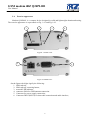
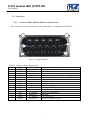
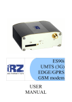
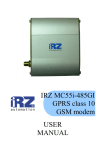
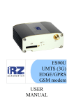
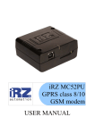
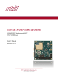
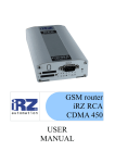
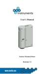
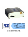
iRZ Q24PL001
GPRS class 10
GSM modem
USER MANUAL
GSM modem iRZ Q24PL001
User Manual
Contents
Safety Requirements ...................................................................................................................................................3
General Information ....................................................................................................................................................4
2.1.
Purpose of the device.........................................................................................................................................4
2.2.
Configuration.....................................................................................................................................................4
2.3.
Parameters .........................................................................................................................................................4
2.4.
Exterior appearance ...........................................................................................................................................6
2.5.
Interfaces ...........................................................................................................................................................7
2.6.
Modem Status Indication ...................................................................................................................................9
3.
Connection and Setting Up........................................................................................................................................10
3.1.
Connection.......................................................................................................................................................10
3.2.
Control, Restarting and Power Off ..................................................................................................................10
1.
2.
2
GSM modem iRZ Q24PL001
User Manual
1. Safety Requirements
Restrictions for the usage of the device in the vicinity of other electronic devices:
• turn off the modem in hospitals or in the vicinity of medical equipment (e.g.
cardiostimulators, hearing aids). It can cause interference for medical equipment;
• turn off the modem in aircrafts. Take measures against accidental activation;
• turn off the modem in the vicinity of gas-filling stations, chemical enterprises, blasting
work places. It can cause interference to technical devices;
• at a short range the modem may cause harmful interference to TV and radio receivers.
Prevent the modem from dust and moisture.
Improper use deprives you of all warranty claims.
3
GSM modem iRZ Q24PL001
User Manual
2. General Information
2.1. Purpose of the device
The modem iRZ Q24PL001 is a structurally accomplished GSM modem designed for reception
and transmission of data, text messages and telecopies. It is excellently adjusted both for mobile
Internet Access and for industrial applications — telemetry, wireless data collection from sensors,
remote surveillance, monitoring and signaling.
The modem is assembled based on the GSM module MC55i Cinterion. The control is performed
by means of standard AT commands. The modem is equipped with light-emitting diodes (LEDs)
enabling to monitor the status of connection.
2.2. Configuration
Complete set of the GSM modem IRZ Q24PL001:
• modem IRZ Q24PL001,
• label,
• factory box.
2.3. Parameters
Basic parameters:
• frequency ranges: GSM 850/900/1800/1900 mHz;
• power output:
o 2W (class 4 for EGSM900),
o 1W (class 1 for GSM1800),
• GPRS class 10;
• MC class B;
• CSD up to 14.4 kbps;
• SMS;
• voice transmission;
• fax group 3: class 1.
Electric power supply:
• power supply voltage from 9 to 30 V;
• absorbed current not more than:
o with power supply voltage +12 V – 300mA;
o with power supply voltage +24 V – 150mA.
4
GSM modem iRZ Q24PL001
User Manual
Physical parameters:
• size not more than 76х53х31 mm,
• weight not more than 100 g.,
• operating-temperature range from -20°С to +50°С,
• storage temperature range from -40°С to +65°С.
Interfaces:
• connector RJ11 for power supply connection,
• connector DB15 for connection of the data cable RS-232,
• audio interface connection,
• connector SMA for GSM antenna connection.
5
GSM modem iRZ Q24PL001
User Manual
2.4.
Exterior appearance
Modem Q24PL001 is a compact device designed in solid and lightweight aluminum housing.
The exterior appearance is represented on Fig. 1.4.1 and Fig.1.4.2.
1
2
3
4
Fig.2.4.1 Front view.
5
6
Fig.2.4.2 Back view.
On the figures the digits signify the following:
1. SIM card tray,
2. SIM card tray extracting button,
3. network LED indicator,
4. connector SMA for GSM antenna connection.
5. Connector for power supply connection,
6. Connector DB15 (RS232) for data cable connection and audio interface,
6
GSM modem iRZ Q24PL001
User Manual
2.5. Interfaces
2.5.1.
Connector DB15 (RS232) (RS232, audio interface)
The connector is used for connection to the control device, exchange protocol RS232.
5
1
6
10
11
15
Fig.2.5.1 Connector DB15
Table 2.5.1 Purpose of the connector pins.
Contact
Signal
Direction
1
DCD
Modem-PC
2
TXD
PC-Modem
3
4
MICP
PC-Modem
5
MICN
PC-Modem
6
RXD
Modem-PC
7
DSR
Modem-PC
8
DTR
PC-Modem
9
GND
general
10
SPKP
11
CTS
Modem-PC
12
RTS
PC-Modem
13
RI
Modem-PC
14
RESET
PC-Modem
15
SPKN
Modem-PC
Purpose
Availability of carrier wave
Data transmission
not used
Non-inversed microphone and power supply input
Inversed microphone input
Data reception
Readiness of data
Availability of data receiver
System housing
Non-inversed headphone output
Availability of transmission
Request for transmission
Call signal
Reset, active low
Inversed headphone output
7
GSM modem iRZ Q24PL001
User Manual
2.5.2.
Power supply connector
The connector is used for connection of electric power supply.
4
3
2
1
Fig.2.5.2 Power supply connector
Table 2.5.2 Purpose of power supply connector pins.
Contact
1
2
3
4
Signal
GPIO
INTR
GND
+ 12В
Purpose
Digital Input / Output
Synchronized interrupt output, active low
System housing
Positive pole of DC supply voltage. Protected with a fuse and the
protection circuit against voltage-surge (with voltage infeed rate
more than 30V) and incorrect polarity.
8
GSM modem iRZ Q24PL001
User Manual
2.6. Modem Status Indication
LED indication is provided in the modem for connection status indication.
Table 2.6.1 Connection status indication
Indication mode
Operation mode
Turned off
Modem is turned off or there is an emergency situation
600 ms on / 600 ms
Modem is not registered in the network
off
75 ms on / 3 s off
Modem is registered in the network
9
GSM modem iRZ Q24PL001
User Manual
3. Connection and Setting Up
3.1. Connection
Before feeding the power supply you need to install the SIM card in the modem (the SIM card
must be enabled). To do this, you need:
• to extract the SIM tray by pressing the SIM tray extract button (Fig. 2.4.1);
• to install the SIM card into the SIM tray;
• to insert the SIM tray with the SIM card into the modem.
No strong physical efforts must be applied while installing the SIM card.
Connect the GSM antenna to the antenna connector, as well as the commutating cable (RS232).
Feed power supply to the modem through the connector RJ11 (Fig. 2.4.2).
Note: GSM antenna, data cables and electrical power unit are not included in the complete set
configuration.
After the power supply feeding, registration occurs automatically, which is signaled by the green
indicator frequent flashing. After the registration is completed, the modem jumps to the operating
mode, the green indicator flashes less frequently (Table 2.6.1).
Note: GSM antenna, switching cables and power supply not included in complete set.
3.2. Control, Restarting and Power Off
The modem control is performed by standard AT commands. For additional information and
support visit the manufacturer’s site – www.radiofid.ru.
Modem restarting can be carried out by the following ways:
• by the program method through AT commands,
• by temporary power-off.
10