1
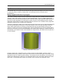
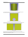
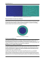
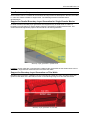
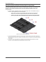
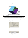
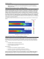
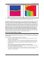
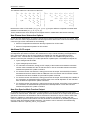
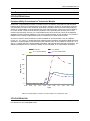
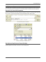
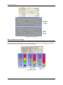
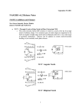
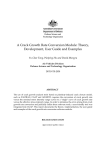
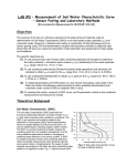
ACE+ Suite V2011.0 Release Notes ACE+ Suite V2011.0 Release Notes ACE+ Suite V2011.0 Release Notes UA/CFD_/11/01/00/A ©1997-2011 by ESI-Group his ESI Group documentation is the confidential and proprietary product of ESI-Group, Inc. Any unauthorized use, reproduction, or transfer of this manual is strictly prohibited. This documentation is subject to limited distribution and restricted disclosure. CFD-ACE™, CFD-ACE+™, CFD-CADalyzer™, CFD-VIEW™, CFD-GEOM™, SimManager™, CFDVisCART™, CFD-Micromesh™ and CFD-FASTRAN™ are registered trademarks of ESI-Group. Portions of this product are owned by third-party software vendors. Revision Information The information in this guide applies to all current ESI CFD products until superseded by a newer version of this guide. Published: November 2011 Disclaimers The documents and related know-how herein provided by ESI Group subject to contractual conditions are to remain confidential. The CLIENT shall not disclose the documentation and/or related know-how in whole or in part to any third party without the prior written permission of ESI Group. About ESI GROUP ESI provides a world leading software editor for the numerical simulation of prototype and manufacturing process engineering in applied mechanics. The key to ESI's success is the use of realistic material physics, providing "as good as real" virtual solutions, in order to replace the lengthy trial and error processes on real prototypes. ESI has developed an extensive suite of coherent, industry-oriented applications to realistically simulate a product’s behavior during testing and real life use; to refine manufacturing processes for desired product performance, and to evaluate the effect of the environment in which the product is deployed. ESI’s products represent a unique collaborative and open environment for End-to-End Virtual Prototyping, thus eliminating the need for physical prototypes during product development. This solution allows a productivity gain, innovation acceleration and significantly reduced costs. For more information about ESI Group, visit www.esi-group.com. About ESI CFD ESI CFD is a technology leader in the field of advanced computational fluid dynamics simulation software backed by more than 20 years of research-based knowledge throughout a wide range of industries. ESI CFD’s broad range of products and services provide all of the necessary tools for advanced multiphysics analysis in a virtual prototype environment, significantly reducing time and expense through comprehensive up-front modeling and simulation. Key focus areas include aerospace, automotive, biomedical, fuel cells, MEMS, microfluidics, plasma and semiconductor. Contact Information for ESI CFD ESI CFD, Inc. 6767 Old Madison Pike, Ste. 600 Huntsville, AL 35806 Phone: (256) 713-4700 Fax: (256) 713-4799 Software Support: [email protected] Software Sales: [email protected] Release Notes ACE+ Suite V2011.0 Table of Contents ACE+ Suite V2011.0 ............................................................................................................ 1 ACE+ Suite of Applications ............................................................................................. 1 Supported Platforms........................................................................................................ 1 Backward Compatibility ................................................................................................... 2 Running Older Versions .................................................................................................. 2 Applications in Maintenance Mode .................................................................................. 2 CFD-GEOM V2011.0 ............................................................................................................ 3 New Features and Improvements.................................................................................... 5 Corrected Problems ...................................................................................................... 13 Known Problems ........................................................................................................... 13 CFD-VisCART V2011.0 ...................................................................................................... 15 New Features and Improvements.................................................................................. 17 Corrected Problems ...................................................................................................... 24 Known Problems ........................................................................................................... 24 CFD-ACE+ V2011.0 ........................................................................................................... 25 New Features and Improvements.................................................................................. 27 Corrected Problems ...................................................................................................... 34 Known Problems ........................................................................................................... 35 CFD-FASTRAN V2011.0 .................................................................................................... 37 New Features and Improvements.................................................................................. 39 Corrected Problems ...................................................................................................... 40 Known Problems ........................................................................................................... 40 CFD-VIEW V2011.0 ............................................................................................................ 41 New Features and Improvements.................................................................................. 43 Corrected Problems ...................................................................................................... 46 Known Problems ........................................................................................................... 46 ACE+ Suite V2011.0 Release Notes v Table of Contents vi Release Notes ACE+ Suite V2011.0 ACE+ Suite V2011.0 This document introduces the V2011.0 Release of the ACE+ Suite of applications. It summarizes the new features and improvements developed in the last 12 months, i.e. since the V2010.0 Release in August 2010. It also includes the list of issues that have been corrected in this Release. ACE+ Suite of Applications The ACE+ Suite includes a broad range of applications that provide the necessary tools for advanced multiphysics analysis in a virtual prototype environment. The complete list of applications is shown below. CFD-GEOM CFD-VIEW CFD-VisCART CFD-CADalyzer CFD-ACE+ CFD-TOPO CFD-FASTRAN SimManager Supported Platforms The V2011.0 ACE+ Suite of applications is supported on the following platforms: Platform Package Canonical Name Windows XP/2003/Vista/2008/Win7 on Intel or AMD (32-bit) pc-windows-nt5-x86 Windows XP/2003/Vista/2008/Win7 on Intel or AMD (64-bit) pc-windows-nt5-x86_64 Linux RedHat Enterprise 6+ on Intel or AMD (32-bit) pc-linux-rhe6-x86 Linux RedHat Enterprise 6+ on Intel or AMD (64-bit) pc-linux-rhe6-x86_64 Linux RedHat Enterprise 5+ on Intel or AMD (32-bit) pc-linux-rhe5-x86 Linux RedHat Enterprise 5+ on Intel or AMD (64-bit) pc-linux-rhe5-x86_64 Linux RedHat Enterprise 4+ on Intel or AMD (32-bit) - deprecated pc-linux-rhe4-x86 Linux RedHat Enterprise 4+ on Intel or AMD (64-bit) - deprecated pc-linux-rhe4-x86_64 Linux Suse 10 on Intel or AMD (32-bit) - deprecated pc-linux-suse10-x86 Linux Suse 10 on Intel or AMD (64-bit) - deprecated pc-linux-suse10-x86_64 Linux Suse 9 on SGI Altix (64-bit) - deprecated sgi-linux-suse9-ia64 Notes V2011.0 applications are not supported on AMD Athlon processors or on Intel Pentium III processors due to the lack of SSE2 support on these CPUs. CFD-GEOM is not supported on Linux Suse 9 (64-bit) CFD-TOPO Solver is not supported on Linux Suse 9 (64-bit) and Linux Suse 10 (32-bit and 64-bit) Browsers: The webhelp system is known to work properly when viewed with Internet Explorer 6+ (MS-Windows), Netscape 6+ (MS-Windows, Linux) or Firefox 3+ (MS-Windows, Linux). It is not recommended to use Google Chrome for this purpose. ACE+ Suite V2011.0 Release Notes 1 ACE+ Suite V2011.0 The next major Release of the ACE+ Suite of Applications will not be supported on the platforms marked as deprecated. On the other hand, support on new platforms, such as Suse 12, is expected in the next major Release. Backward Compatibility There are no known backward compatibility problems with the ACE+ Suite of Applications, except for the issue related to CFD-GEOM V2006 (or earlier) scripts, as mentioned below. Due to numerous changes to the core of CFD-GEOM in V2007.6 the “Python wrapped” functions also changed significantly. This made it impossible to retain backwards compatibility for Python scripts. This means that CFD-GEOM V2007.6 or later versions cannot process CFD-GEOM V2006 or earlier Python scripts. It is indeed an unfortunate side-effect and one that was not taken lightly but we felt that it was necessary in order to build a better CFD-GEOM core. So if you plan to use CFD-GEOM V2006 script files you have a couple of options: 1. Keep CFD-GEOM V2006 installed and run your V2006 scripts through that version. Your V2011.0 license will allow V2011.0 and all older versions (including V2006) to run. The V2011.0 versions of CFD-ACE+ and CFD-FASTRAN will read and use V2006 CFD-GEOM generated DTF files with no problem. 2. Convert your CFD-GEOM V2006 script files to V2011.0 format. This is a manual process of translating the V2006 script file to make use of V2011.0 script language. In most cases it is just a matter of replacing the function calls with equivalent V2011.0 syntax (and leaves all your program control structure in place). ESI Group customer support staff can advise you on how to do this. Running Older Versions The 2011.0 software can be installed with existing 2010.0, 2009.4, 2009.2, and earlier ESI software directories. You will continue to be able to use old and new versions of the software, which will allow as much time as needed for transition. If you install 2011.0 software with existing 2010.0, 2009.4, 2009.2, or earlier software, you must remember to modify your PATH so that the newest UTILS directory, i.e. $ESI_HOME/2011.0/UTILS/bin, appears first in your PATH. Then you may run older versions of the software using the –runver <version> option. For example, on Linux systems, assuming a Bourne-type shell: % export PATH=$ESI_HOME/2011.0/UTILS/bin:$PATH (Bourne-type shell syntax) % CFD-GEOM –runver 2009.4 (runs 2009.4 CFD-GEOM) Applications in Maintenance Mode CFD-TOPO V2011.0 is a Maintenance Release of the application. SimManager V2011.0 is a Maintenance Release of the application. CFD-CADalyzer V2011.0 is not being offered. Users can continue running earlier versions of this application using the –runver option as explained in the previous section. 2 Release Notes ACE+ Suite V2011.0 CFD-GEOM V2011.0 Release Notes ACE+ Suite V2011.0 Release Notes 3 CFD-GEOM V2011.0 4 Release Notes ACE+ Suite V2011.0 CFD-GEOM V2011.0 New Features and Improvements CFD-GEOM V2011.0 includes all new features and improvements developed in the last 12 months, i.e. since the V2010.0 release in August 2010. The following sections summarize these developments. Newly Supported Surface Topologies The surface modeling module has been expanded to support almost any standard surface topology output by major CAD systems, including non-manifold topologies. This new capability significantly increases the success rate during import of SAT, Parasolid, STEP, IGES, and other CAD formats (i.e. the need to repair topologies not understood by earlier versions of CFD-GEOM should be virtually eliminated). It also allows for easier modeling of special constructs such as baffles. Newly supported topologies include but are not limited to the following: A periodic surface with a seam curve: Notice the end points of the seam curve in the image below (the one running vertically). Each bounds 3 curves (the closed curves on the top and bottom use them twice). When a point entity on a surface is used other than twice by the bounding curves on the surface, we refer to this as a non-manifold surface. When meshing this type of non-manifold surface, the mesh on the seam curve must be embedded in the surface mesh. Note that, in earlier versions of CFD-GEOM, such surfaces could not be modeled as a single surface, but rather had to be split into 2 or more surfaces. A periodic surface with a seam curve Periodic surfaces with “separation loops”: In earlier versions of CFD-GEOM, a surface could be bounded exclusively by exactly 1 outer loop of curves and 0 or more inner loops of curves (i.e. holes). Separation loops do not fall into either category. They define the outer boundaries of the surface, but neither lies inside the other. Moreover, any holes that might be cut in the surface would not lie inside them either. The following figure shows an example of such a surface with separation loops. ACE+ Suite V2011.0 Release Notes 5 CFD-GEOM V2011.0 A periodic surface with separation loops Non-manifold surfaces in which internal holes touch the outer boundary: Note that the hole must share a common point entity with the outer boundary, as in the following figure. Non-manifold surfaces in which internal holes touch the outer boundary A surface with a spur (the stray curve hanging in the surface interior): Note, in the mesh on the right, how the spur is captured. Spurs can be used in 2-D models to represent thin walls (baffles). A surface with a spur Spurs may also be used in 3-D modeling to attach baffles to other surfaces. In the following illustration, notice how spurs are used to connect the baffle to the two lower surfaces. During meshing this guarantees continuity between the surfaces. 6 Release Notes ACE+ Suite V2011.0 CFD-GEOM V2011.0 Spurs connecting baffle to lower surfaces Surfaces without outer boundaries: Closed surfaces such as spheres and toroids need not have outer boundaries and may contain only holes, as in the following torus. Surfaces without outer boundaries New Advanced Trimming Tool The Advanced Trimming Tool, located in the Trimmed Surface Modification toolbox, allows the user to create new surfaces or redefine the boundaries of an existing surface. To create a new trimmed surface, an untrimmed surface and a set of curves defining all the boundaries of the new surface should be selected. To redefine the boundaries of an existing trimmed surface, the surface should be selected – the curves that currently bound the surface will be automatically selected. Then, curves can be deselected or additional curves selected to bound the surface. This allows the user to simultaneously add/remove holes, spurs and interior free curves, and to replace curves with Edge entities, and vice versa. Whether creating a new surface or redefining an existing surface, the order in which curves are selected is not important. As long as they lie on the surface and collectively form a valid topology, CFD-GEOM will determine their relationships. Modifications to surfaces that belong to shells or semistructured domains are disallowed if they would break those entities (e.g. cause a shell to open). In the scripting interface, this capability is available through Ggeometry.TrimSurfaceAdvanced. New Boundary Layer Meshing Option The boundary layer meshing algorithm has been modified for a new option which controls the initial thickness; in earlier versions, the only option was to specify the exact desired thickness of the first layer. The new option allows the specification of a factor applied to the local cell size to control thickness. The first image below shows the boundary layer growth with an exact specified thickness while the subsequent image shows the optional behavior where the growth is based on a local surface element size; notice the element size is dependent on the local surface cell size. The associated script function has been modified to: Gmesh.GloballyEnableBoundaryLayerMeshing(num_layers,initial_thickness,growth_rate,local_gro wth,local_growth_factor). ACE+ Suite V2011.0 Release Notes 7 CFD-GEOM V2011.0 The last two arguments are defaulted to 0 and .1, respectively and any previous scripts will continue to work. Set local_growth to 1 if the boundary layer height should be a function of the local surface element size. Boundary Layer generated using the two options Improved Boundary Layer Robustness The boundary layer meshing has been improved for robustness and can now handle thin-walls, i.e. baffle surfaces. At this time, however, boundary layers may not be generated from thin-walls. The image below shows an example with thin-wall surfaces; notice how the layers are terminated to avoid intersecting the thin-walls. Boundary layer generated on a model with thin-walls Additionally, the meshing has been improved to account for additional shells that may be present in the domain. The image to the left shows one domain with two shells; the green surfaces represent an internal void or shell. Notice that the internal shell is very close to other surfaces such that if boundary layer meshes are generated from these surfaces there would be layer intersection thus causing a 8 Release Notes ACE+ Suite V2011.0 CFD-GEOM V2011.0 volume meshing failure. The image on the right shows an example where boundary layers have been generated on the interior shell and some of the surfaces of the outer shell. Boundary Layer generated on a model with multiple shells Limitation: As mentioned above, at this time, boundary layers cannot be generated on thin-walls. New Discrete Surface Meshing Options Quad-dominant and quad-paved meshing (along with the default triangle meshing) is now available. The default mesh type is unspecified and the mesh type setting in discrete surface meshing GUI will be used on the selected surfaces. The mesh type can be directly set on the selected surfaces by selecting the desired mesh type setting and pressing the Apply button. Shown below are examples of the mesh types as applied to a discrete surface. Triangle, quad-paving and quad-dominant meshes on a discrete surface New Cell Size per Surface for Discrete Surface Meshing Discrete surfaces may now be prescribed different cell sizes for surface meshing. The minimum of the cell size values is used on common boundaries between surfaces. The global value is used for those surfaces which have not been prescribed a cell size. The image below shows an example where the cell size on the right surface is four times smaller than that of the one on the left; notice that the common boundary between the surfaces has been meshed with the smaller size. ACE+ Suite V2011.0 Release Notes 9 CFD-GEOM V2011.0 Different cell sizes specified on adjoining discrete surfaces Discrete Surface Creation from Outlines Discrete surfaces may now be created by selecting the outlines of existing discrete surfaces. The example below shows the original discrete surface in cyan and the interior blue surface was created by selecting the interior outlines (in orange bordering the blue surface). The tool which allowed creation of discrete surfaces from geometric lines remains available. This function is not scriptable because discrete surface outlines are not geometric constructs. Discrete surface creation from outlines 2-D Honeycomb Meshing The honeycomb meshing tool has been extended to support 2-D meshing on models consisting of triangulated trimmed surfaces lying in the XY plane. This tool has been renamed from “3-D Honeycomb Meshing” to simply “Honeycomb Meshing”. When this tool is invoked, it will determine the model characteristics and invoke the 3-D or 2-D mesher as appropriate. In the scripting interface, this capability is available through GMesh.Generate2DHoneycombMeshes. Modifications to CAD File Open/Import The CAD file reading/import dialogs have been modified to allow reading of SAT, CATIA, Pro/E, Parasolid, Unigraphics and STEP as discrete models. This option can be significantly faster when a non-CAD model is sufficient. In addition, the generated solids will usually be water-tight; if spurious outlines are noticed then the “Merge Nodes” option can be utilized from the Discrete Surface menu. The IGES reader does not support this option. In addition, when reading the above CAD formats in the traditional manner (i.e. non-discretely), certain behavioral changes are likely. For example, periodic surfaces are no longer split into 2 surfaces; instead, the original topology is preserved. This should help reduce the number of artificial small features that may have been introduced by earlier versions of CFD-GEOM. Such features can significantly drive up cell counts during mesh generation. Moreover, any spurs present in surfaces will 10 Release Notes ACE+ Suite V2011.0 CFD-GEOM V2011.0 be preserved (see Newly Supported Surface Topologies for more information). Note that certain surface topologies are not supported by the IGES standard. If you intend to export geometries for import into other systems, you may need to export to SAT, which supports all topologies that can be generated in or imported into CFD-GEOM. Even then, there is no guarantee that downstream applications will support all possible topologies. Improved IGES Reader The IGES reader will now process shells and solids present in files which follow the IGES 5.3 specification. The IGES reader has gone through a revision that makes file import yield the proper results in most cases especially when importing files containing the subfigure entities and their transformations. Additionally, the reading process should be 2-3 times faster and this will be especially noticeable during the reading of large files. Improved Geometry Revolution Tools Most geometry tools for creating revolved surfaces now support full 360 deg revolutions. Note, however, that the volume grid revolution tool still does not support this at this time. Improved STL Import/Read The STL file importer/reader now allows the selection of multiple files and the reader is now faster and able to handle multiple geometries in a single file. Note that the names of files may no longer be input but must be selected due to an issue in the FOX library. Improved Entities Projection Tool The entities projection tool has been improved to allow the projection of points, lines and curves onto discrete surfaces. Previously, only CAD surfaces were supported. Improved Advancing Front Triangle Meshing The advancing front triangle mesher has been improved to yield higher quality meshes especially near boundaries and in many cases where previously the mesher could give small angles or inverted cells. The mesher is now also able to handle internal curves and is 3-5 times faster. Improved Topology Queries Tool In the Topology Queries tool, several antiquated types of queries (mostly involving loops) have been removed. In addition several useful queries taking advantage of the new surface topology system have been added. Modifications to Graphical User Interface (GUI) Layout of Meshing Tools The shell creation, domain creation, and the thin-wall creation/removal tools have been moved from the Shell and Unstructured Domain Options in the Mesh tab to the Solid and Wireframe Option in the Geometry tab. The semi-structured domain creation tool has also been moved from the Shell and Unstructured Domain Options to the Structured and Semi-Structured Domain Options. Additionally, the Shell and Unstructured Domain Options toolbox has been removed in its entirety. In addition, the journaling/scripting functions CreateAllDomains, CreateAllDomains2, CreateShell, CreateDomain, AddBafflesToDomain and RemoveBafflesFromDomain have been replicated from the GMesh to the GGeometry module and all future scripts should use GGeometry as the python module specifier for these functions. Improved Surface Mesh Quality Tool The surface mesh quality tool has been improved to automatically select those surfaces which violate the given mesh quality criteria. The user can then simply type Ctrl+r in the graphics window to view only those surfaces. The cell centroid check does not select the surfaces as it combines all given surface meshes into a single mesh prior to the check and it cannot determine which surfaces violate the criteria. ACE+ Suite V2011.0 Release Notes 11 CFD-GEOM V2011.0 New Tip of the Day Dialog To inform users of critical changes to the GUI or to provide useful usage tips a “Tip of the Day” tool is available under the Help menu. The user can optionally turn on/off the dialog to display when CFDGEOM starts from within the dialog. 12 Release Notes ACE+ Suite V2011.0 CFD-GEOM V2011.0 Corrected Problems The following is the list of issues addressed in this release. In certain 2D cases, triangle and/or quad meshes exported to DTF using the ‘Simplify’ option would produce files containing cells with negative volumes. This issue has been resolved. Issue related to surface splitting failure for certain type of surfaces has been resolved. Under certain circumstances, when outputting 3D meshes containing overlapping face entities, an invalid DTF file would be produced (only when the ‘Simplify’ option was used, not otherwise). Such an attempt now triggers an error message and suggestions are made for fixing the problem. Known Problems These are the known serious problems with the latest release. Some or all of these problems may be corrected in a future release. Updating Existing DTF Files: Updating existing DTF files from models containing polyhedral zones (i.e. coarsened blocks) is not currently supported. Only “fresh” DTF files may be written from models containing such grid types. Undo Operations in the Edge Editor: Undo is unavailable in the Edge editor. If the user quits the edge editing session at any point where the system is in an error state (faces with opposing edges without the same number or grid points) CFD-GEOM will reinstate the grid system to the last known “good” state. Difference in ACIS: All platform except, pc-linux-rhe4-x86 and pc-linux-rhe4-x86_64 have been upgraded to ACIS version 22.0.0. These two platforms remain at ACIS version 18 and therefore, there may be some differences in performance. Limited CAD Import Options on 64-bit Linux Platforms: Several CAD import options (Parasolid, UG, Pro/E, Catia V4 and Step) are available on 32-bit Linux platforms but not on 64-bit Linux platforms due to the limitation in ACIS version 22.0.0. This limitation is expected to be removed in a future release. ACE+ Suite V2011.0 Release Notes 13 CFD-GEOM V2011.0 14 Release Notes ACE+ Suite V2011.0 CFD-VisCART V2011.0 Release Notes ACE+ Suite V2011.0 Release Notes 15 CFD-VisCART V2011.0 16 Release Notes ACE+ Suite V2011.0 CFD-VisCART V2011.0 New Features and Improvements CFD-VisCART V2011.0 includes all new features and improvements developed in the last 12 months, i.e. since the V2010.0 release in August 2010. The following sections summarize these developments. Support for Parallel Boundary Layer Generation for Single-Domain Mesher In earlier versions, boundary layer generation was supported only in serial mode. In V2011.0, boundary layer generation for single-domain meshes is supported in parallel mode as well. This enhancement will significantly improve turnaround time for mesh generation. Boundary Layer generation in parallel mode Limitation: As thin-walls are not supported in parallel mode, the benefits of this enhancement can be realized for single-domain meshes that do not include thin-walls. Support for Boundary Layer Generation on Thin-Walls Boundary layer generation capability has been extended to handle thin-walls. Boundary layers are grown on both sides of the thin-wall, as shown in the following image for a thin-wall heat shield. Boundary Layer generation on Thin-Wall ACE+ Suite V2011.0 Release Notes 17 CFD-VisCART V2011.0 Limitations: • The boundary layers will gradually terminate at the edges of the thin-wall. • As thin-walls are not supported in parallel mode, this enhancement is limited to use in serial mode. New Local Thickness Specification for Boundary Layer Generation When the surface mesh size is not uniform and varies considerably through the model, a constant thickness specification for the boundary layer may not always be suitable or sufficient. In this version, a new boundary layer growing method (Local Thickness) is available together with the original (and previously available) Absolute Thickness method. The Local Thickness method allows users to specify an area factor (instead of a constant first layer thickness) that allows the boundary layer thickness to vary locally according to the size of the surface mesh. This area factor is a multiplicative factor and is expressed mathematically as Initial Thickness = Area Factor x Representative length here, Representative Length is a function of the local surface element cell size. Local Thickness Boundary Layer Growing Method New Mesh Extrusion Feature Starting with V2011.0, a new option, that allows outward extrusion of surface meshes, is available to users. After the volume mesh has been generated, this option can be used to extrude the projected surface mesh outwards (outside the volume domain) in the direction normal to the surface mesh. The user needs to specify the number of layers, initial thickness and growth factor for this extrusion. A typical application of this feature is windshield modeling. Once the mesh inside the vehicle cabin has been generated, this feature can be used to extrude the surface mesh on the windshield outwards – thus generating the windshield thickness or volume. Limitation: Currently this feature is available only in batch mode. Extrusion Layer generation 18 Release Notes ACE+ Suite V2011.0 CFD-VisCART V2011.0 New Cancel button to Terminate Meshing Operation In CFD-VisCART V2011.0, the Cancel mesh generation feature has been introduced. This feature or capability allows users to cancel a meshing operation without losing/killing the session or terminating the GUI. When a meshing operation (base mesh generation, mesh improvement, boundary layer generation or grid adaptation) is kicked off, a dialog pops-up displaying the Status bar, the Progress bar and a Cancel button. Dialog with Status bar, Progress bar and Cancel button The Status and Progress bars keep dynamically updating, providing information to the user as to which sub-operation is taking place and how it is progressing. If the Cancel button is pressed, the system will prompt the user for a confirmation and then terminate the meshing operation. Users have the option (under EditPreferencesAdvanced) to specify what should happen when a meshing operation is canceled: Go back to no mesh state Go back to the mesh that existed prior to the canceled meshing operation OR New Cylindrical Bounding Box In earlier versions, the bounding box could only be Box shaped. In this version, a new Cylinder shaped bounding box option has been introduced. With this option, additional inputs - for axis direction and mesh handling on the curved cylindrical bounds - need to be specified. The mesh on the curved cylindrical bounds can be specified to be projected (Body-fit) or remain stair-stepped. Cylindrical bounding box with ‘Body-fit mesh on side’ option ON and OFF ACE+ Suite V2011.0 Release Notes 19 CFD-VisCART V2011.0 Extended and Enhanced Refine Cells Near High Curvature Option If the Refine Cells Near High Curvature option is used during mesh generation, the mesh gets refined near areas of the model that have high curvatures or sharp features. This option, that has been available in CFD-VisCART for several versions, has been enhanced/extended in V2011.0 as mentioned below: In earlier versions, parameters ‘Factor’ and ‘Feature Angle’ were not accessible to users. In V2011.0, these parameters can be user specified o ‘Factor’ refers to the ratio of the specified surface cell size to the cell size after refinement. In other words, higher the value the more intense the refinement. o ‘Feature Angle’ refers to the dihedral angle between facets and refinement will take place only at locations where the dihedral angle is greater than the specified value. Effect of Factor and Feature Angle inputs 20 The enhanced algorithm detects and refines high curvature areas not just within a patch but between patches as well. Also, edges connecting more than 2 facets are checked and refined if necessary. This option, which was limited to the Single-Domain and Shrink-Wrap meshers in earlier versions, is now available with the Multi-Domain mesher as well. Release Notes ACE+ Suite V2011.0 CFD-VisCART V2011.0 New Preserve Boundary Between Two Patches Option If two adjoining patches are coplanar or have a very small dihedral angle between them, the boundary between these patches may not be properly captured with the existing Preserve Features option. In V2011.0, a new option, Preserve Boundary Between Two Patches, has been introduced for this purpose. Also, in addition to capturing explicit boundaries (boundary between adjoining patches) this option enables capturing of implicit boundaries (intersection of overlapping parts, etc.) as well. Limitation: This option is only available with the Single-Domain mesher. Improved preservation of coplanar patch boundaries and implicit boundaries in V2011.0 New Suppress Option for Surfaces, Domains, Sources and Gaps This new option allows geometry surfaces, sources, domains, and gaps to be suppressed. Suppressing an entity makes it ‘invisible’ to the mesher during subsequent mesh generation. This means that although the entity remains in the model and continues to be visible to the user, it does not participate in any meshing operations. This option should make case studies more convenient. Suppress/Unsuppress buttons and Suppression status column in the Explorer ACE+ Suite V2011.0 Release Notes 21 CFD-VisCART V2011.0 New Domain Marker Positioning Option To set the location of a domain marker, a new option has been introduced that positions the domain marker at the center of the line joining two selected points or at the average center if more than two points are selected. Selected points and resulting position of the Domain Marker Reduced VGD File Size The following enhancements implemented in this version will result in smaller VGD files: Surface source storage has been optimized and thus VGD files with surface sources will be smaller in size than in earlier versions. While saving the mesh in the VGD file, users will see options that can result in a reduced VGD file size. These options pertain to retaining the Cartesian cells as they are or converting them to Polyhedral cells before saving. The extent of file size reduction with such a conversion is case-dependant as explained in the user manual. Reading and writing of gzipped VGD files (VGD.gz) is now supported. Save Mesh Options and VGD.gz support 22 Release Notes ACE+ Suite V2011.0 CFD-VisCART V2011.0 Support for Reading/Writing gzipped VGD, NASTRAN and STL Files In addition to gzipped VGD files, gzipped NASTRAN and STL files can also be read/written directly with CFD-VisCART V2011.0. This new feature provides great convenience when disk space is limited. ACE+ Suite V2011.0 Release Notes 23 CFD-VisCART V2011.0 Corrected Problems The following is the list of issues addressed in this release. Issues related to and resulting from the existence of ‘open’ cells in the mesh (invalid mesh, domain decomposition failures, etc.) have been resolved by adding comprehensive protections and checks that prevent the creation of such cells. Issues related to and resulting from the existence of duplicate points/faces in the mesh (invalid mesh, domain decomposition failures, etc.) have been resolved by adding comprehensive protections and checks that prevent the creation of such points/faces. Improved robustness of mesh generation in parallel mode has resulted in the resolution of certain issues encountered in this mode (run failure, zero cells in a zone, etc.). Cell count balance between the various processors (or zones) in parallel mode has also been improved. Improved robustness of thin-wall handling has resulted in the resolution of certain issues (meshing errors for thin-walls with T junctions, domain decomposition failures, thin-wallpreprocess failures, poor preservation/capture at wall/thin-wall intersections, etc.) Protection has been added to hide the option (in interactive mode) for saving Shrinkwrap mesh in the VGD file as this is not supported. Warning message is written out for the same in batch mode. Known Problems These are the known serious problems with the latest release. Some or all of these problems may be corrected in a future release. 24 Projected Single Domain mesher takes much longer to complete mesh generation if ‘Feature Preservation’ is activated and the final mesh quality may not be as good as the one generated without ‘Feature Preservation’. The Multi Domain mesher may encounter problems in handling a domain interface if two surfaces are present at that location but they don’t match exactly. Several CAD import options (Parasolid, UG, Pro/E, Catia V4 and Step) are available on 32-bit Linux platforms but not on 64-bit Linux platforms. This limitation is expected to be removed in a future release. Release Notes ACE+ Suite V2011.0 CFD-ACE+ V2011.0 Release Notes ACE+ Suite V2011.0 Release Notes 25 CFD-ACE+ V2011.0 26 Release Notes ACE+ Suite V2011.0 CFD-ACE+ V2011.0 New Features and Improvements CFD-ACE+ Solver CFD-ACE+ Solver V2011.0 includes all new features and improvements developed in the last 12 months, i.e. since the V2010.0 release in August 2010. The following sections summarize these developments. Enhanced CAFVM Discrete Ordinate Method for Radiation The CAFVM implementation in CFD-ACE+ Solver V2011.0 has been enhanced in the following ways: Accurate computation of radiative intensities and fluxes at boundary surfaces oriented arbitrarily with reference to the Cartesian coordinate planes. The enhancement based on a subdivision approach, as shown below, has the following impacts: o Increased computational accuracy at arbitrarily oriented opaque surfaces o Correct purely specular treatment of arbitrarily oriented symmetry surfaces. In earlier versions of CFD-ACE+, symmetry surfaces not aligned with the Cartesian coordinate planes were treated as partly diffuse. Unit sphere subdivision at a Boundary Face The degree of specularity of reflection at a boundary surface can now be explicitly specified. The value range is [0,1] with the extreme bounds representing purely diffuse and purely specular reflectivity. Accurate and robust subdivision treatment of Fresnel interfaces - interfaces separating media of different refractive indices and involving both reflection and transmission of radiation. The spectral reflectivity and transmissivity are computed internally based on an ideal electromagnetic analysis of dielectric interfaces. Optics at a Fresnel Interface ACE+ Suite V2011.0 Release Notes 27 CFD-ACE+ V2011.0 Refractive index of a medium can now be explicitly specified as a volumetric property. In earlier versions, the refractive index was tacitly assumed to be unity in the computation of blackbody emission. Improved Plasma implementation with Wave Effects An enhanced implementation is available, with this release of the CFD-ACE+ Solver, to enable the modeling of electromagnetic wave effects in large area, high frequency capacitively coupled plasma reactors. This implementation allows for the solution of the magnetic vector potential in time domain allowing mutual intra RF cycle feedback with the computation of plasma conductivity. Electric field equations that drive charged species transport are computed from the contributions of the gradient of the scalar potential and the time derivative of the vector magnetic potential. The total power absorbed by electrons includes the so-called electrostatic and electromagnetic (inductive) power contributions. For the most part, the model setup follows the traditional CCP model available so for. The additional inputs include checking the Magnet Module and setting the relevant magnetic options for enabling the computations to include wave effects. The following example (discharge generated in Argon) shows the improvement in results with wave effects. Wave Effects in a discharge generated in Argon Improved Linear Solver and Preconditioner Choices CFD-ACE+ provides a set of linear solvers and preconditioners to find the solution for the set of linear equations generated at each cell of the discretized model. The choice of linear solver and matrix preconditioner can have a major impact on the computation time and solution quality. Starting with V2011.0, CFD-ACE+ will provide the following choices of linear solvers and matrix preconditioners. Solvers: Conjugate Gradient Squared (CGS) Solver Generalized Minimum Residual (GMRES) Solver Algebraic Multigrid (AMG) Solver Preconditioners: Incomplete LU Factorization (ILU[k]) Preconditioner Symmetric Successive Over Relaxation (SSOR) Preconditioner Smoothed Aggregation Algebraic Multigrid (SA AMG) Preconditioner Users can choose any combination of solver and preconditioner for each variable being solved. In general, finding the best choice for solver and preconditioner is a complex task and is dependent on the application/problem modeled. The default choices provided by CFD-ACE+ reflect a balance 28 Release Notes ACE+ Suite V2011.0 CFD-ACE+ V2011.0 between solver robustness, complexity and scalability. The default settings provided for each variable/solver/preconditioner should be sufficient for most cases. For users interested in exploring these options, an ordering of the available linear solvers and preconditioners in increasing cost per iteration is provided in the table below. Solver Preconditioner Generalized Minimum Residual (GMRES)1 Symmetric Successive Over Relaxation Conjugate Gradient Squared (CGS) Incomplete LU Factorization (ILU[k])2 Aggregation Algebraic Multigrid (AMG) Smoothed Aggregation Algebraic Multigrid (SA AMG)3 1 Low cost depends on a low value of the restart parameter. Cost is equivalent to a direct solution cycle with unlimited restart. 2 Cost increases with the value of k. The default value of k is 0. 3 Cost includes the setup cost, which can be amortized if the related hierarchy is constructed only periodically. The additional solvers provided with this release come from the Portable, Extensible Toolkit for Scientific Computation (PETSc). If any of the PETSc solvers are called, the CFD-ACE-SOLVERPLATFORM-MPI executable will be launched and all cases (single or multi-processor) will be run as if in parallel mode. Solver options for the Flow module Improved Domain Decomposition Efficiency The domain decomposition utility has undergone a number of internal modifications that have significantly improved processing times for all types of meshes. In particular, a number of memory management changes have been made. Also, some processing sequences were re-ordered for better efficiencies. These and other improvements yield turn-around times as little as half that of previous versions for certain simulations such as large polyhedral meshes produced by CFDVisCART. ACE+ Suite V2011.0 Release Notes 29 CFD-ACE+ V2011.0 Generalized Gradient and Divergence Calculation Options The gradients of scalar variables and the divergences of vector variables in a computational solution methodology are repeatedly calculated and used throughout the solution cycle. These gradients and divergences are calculated, for example, to form discrete estimates of gradient and divergence terms that appear in the relevant governing equations, to calculate interpolated and extrapolated values of variables, and to compute derived quantities from fundamental physical laws and constitutive relations. In earlier versions, most gradients and divergences were calculated using the Green-Gauss method. With this V2011.0 release, a Least-Squares method is being introduced in a generalized form, and the user can now select the default method for calculating gradients and divergences from among these two methods so that most of the gradient and divergence calculations in the CFD-ACE+ Solver will be performed using the selected method. The reason why not all gradient and divergence calculations will be performed using the method selected by the user is that the gradient calculations for some variables in the Solver, such as a few in the electro-magnetics module, are purposely hard-wired (for accuracy and consistence reasons) to always use a Least-Squares approach, regardless of the option chosen in this section, while some gradients in the flow and heat-transfer modules are purposely hard-wired (for stability and consistence with other solvers) to always use a Green-Gauss approach. The Green-Gauss and the Least-Squares approaches are the only approaches that enable the gradients and divergences to be calculated in a uniform manner for all types of cells, including the arbitrary polyhedral type. To select the default gradient and divergence calculation method, the user can toggle between the two available alternatives in the appropriately-labelled pull-down menu in the Adv (Advanced) sub-tab, under the SC (Solution Control) main tab in the CFD-ACE+ GUI. The default option selection remains the Green-Gauss method, which was the default method in earlier releases of the CFD-ACE+ Solver. Neither of these two gradient calculation methods currently requires any additional parameters or user inputs. In general, the Green-Gauss and the Least-Squares methods generate similar overall solution accuracy, especially if a solution converges well. The Least-Squares approach usually yields slightly greater accuracy and slightly faster convergence, and these advantages become more pronounced with increasing mesh skewness and increasing gradient magnitudes. However, the Least-Squares approach also requires more memory and more computational effort, so it is best to use this approach only when accuracy has a higher premium than turn-around time or conservation of memory usage. New VOF Boussinesq Approximation The Boussinesq Approximation modifies the incompressible Navier-Stokes Equations by introducing a source term in the momentum equation that models the effects on the flow field of thermally-induced buoyancy forces. The advantage of this approximation is that the ability to model the buoyancy effects of a temperature-dependent density is gained but without losing the incompressible form of the equations and all its attendant simplifications and computational benefits. The disadvantage of this approximation is that its validity and accuracy are degraded with increasing buoyancy forces. In earlier versions, the Boussinesq Approximation was implemented only for incompressible homogeneous fluids. In this V2011.0 release, this implementation has been generalized and extended for invocation with the VOF Module, enabling the simplified modeling of the effects of thermallyinduced buoyancy forces in flow-fields containing two immiscible fluids with arbitrarily different properties. An example of such flow-fields is shown in Figures 1(a) and 1(b) below, wherein an enclosure with a hot right wall and a cold left wall contain two fluids in a vertical gravity field, and wherein the buoyancy currents in the two fluids are clearly identifiable. 30 Release Notes ACE+ Suite V2011.0 CFD-ACE+ V2011.0 (a) The velocity field and VOF function. (b) The temperature field. The velocity, VOF, and temperature fields computed with the Boussinesq Approximation for two immiscible fluids under the action of gravity and the resulting thermally-induced buoyancy forces. The Boussinesq Approximation is activated, set-up, and used for two-phase simulations in the same way that it was used for single-phase simulations; the only difference is that if a second phase is present, then the volumetric coefficient of thermal expansion and the reference temperature for that second phase must also be provided (in addition to the corresponding values for the first phase). All other model inputs and parameters remain the same as in earlier versions of the CFD-ACE+ Solver. The guidelines, and the validity and accuracy requirements for the Boussinesq Approximation also apply to two-phase flows in the same way that they do for single-phase flows. However, when a twophase mixture is present, the Boussinesq Approximation imposes the full gravity force vector (in addition to the buoyancy force vector), resulting in a superposed hydrostatic pressure field for twophase flows, while this superposition is purposely omitted for single-phase flows. This difference between the treatments for the single-phase and the two-phase situations is dictated by theoretical requirements and should be borne in mind when visualizing the results of the pressure-field results and also when applying boundary conditions on inlet and outlet boundaries. New Full Anisotropic Material support CFD-ACE+ users can now include full anisotropic material properties in their linear structural analysis. In earlier versions, anisotropic analysis was restricted to orthotropic materials only. In addition, users had to specify material properties in engineering form such as Young’s Modulus, Shear Modulus and Poisson’s Ratios. With this release, the following enhancements have been made. Users can now choose between Isotropic, Orthotropic (Anisotropic in older versions) and Anisotropic material properties. For Orthotropic materials, users can now enter the elastic stiffness matrix directly or enter available engineering data such as Young’s Modulus, Shear Modulus and Posisson’s Ratio. Anisotropic materials can be specified using all 21 independent elements of the elastic stiffness matrix. User subroutine capability has been made available to all inputs through the ustructural_property subroutine template. This includes the engineering data components in each direction and the stiffness matrix itself. User subroutine capability has also been made available for specifying material axes through the udirection subroutine template. This allows users to fully control the material axes direction on a cell-by-cell basis. ACE+ Suite V2011.0 Release Notes 31 CFD-ACE+ V2011.0 The stiffness matrix for a 3D case is of the form: C11 C12 C 22 sym C13 C 23 C 33 C14 C 24 C 34 C 44 C15 C 25 C 35 C 45 C 55 C xxxx C16 C 26 C 36 ⇐⇒ C 46 C 56 C 66 C xxyy C yyyy sym C xxzz C yyzz C zzzz C xxyz C yyyz C zzyz C yzyz C xxxz C yyxz C zzxz C yzxz C xzxz C xxxy C yyxy C zzxy C yzxy C xzxy C xyxy Note that the order in CFD-ACE+ (xx, yy, zz, yz, xz, xy) may be different compared to material data available in the literature (xx, yy, zz, xy, xz, yz). These enhancements were developed and implemented in collaboration with Drexel University. New Plasma User Subroutine Options In CCP and ICP applications, an option to set the source terms in the model can be very useful. With this in mind, the current implementation has been improved to allow users to set source terms through a usource type of user subroutine for the following: Electron Temperature and Electron Density equations for CCP models Electron Temperature equation for ICP models. Additional CCP output Capacitively Coupled Plasmas (or CCPs) are often used in the semiconductor industry to sustain etch and deposition processes involved in the manufacture of chips. While simulating such applications, users need to be able to gain as much insight as possible from the data generated from their simulation runs. Towards this end, additional CCP outputs are now available using either input options in the GUI (Out->Graphic) or via the Special DTF update option. The additional outputs are Cycle averaged electric fields Cycle averaged species fluxes For volumetric mechanism, writing (to DTF output) of the forward and backward volumetric reaction rates in additional to the net reaction rate in case of reversible reactions has been enabled via special DTF update command. For surface reaction mechanisms, writing (to ascii text file output .CVD.RATES) of forward and backward surface reaction rates in additional to the net reaction rate for surface reaction mechanisms has been enabled via special DTF update command. For surface reaction mechanisms, writing (to ascii text file output .CVD.FRXN) of the details of the contribution of individual surface reaction steps to the overall deposition or etch rate has been enabled via special DTF update command. For surface reaction mechanisms, writing (to ascii text file output .CVD.FSPC) of the details of the contribution of individual bulk species to the overall deposition or etch rate has been enabled via special DTF update command. New Gas Species Mole Fraction Output In simulations involving multiple species, material balance can be performed either through mass fractions or mole fractions. CFD-ACE+ provides species mass fractions as an output when gas phase species are involved in the simulations. When reactions are involved, it may be useful to seek mole balance in addition to mass balance as an indicator of solution convergence. Starting with this V2011.0 release, species mole fractions can also be written to the DTF file by activating the option in the GUI under OutGraphicsGas-Chemistry. The solution can be viewed in CFD-VIEW using variables of the form <species_name>_mol_fraction. 32 Release Notes ACE+ Suite V2011.0 CFD-ACE+ V2011.0 New Gas Phase reaction mechanism for Ar/NF3 mixtures A gas-phase reaction mechanism for low temperature plasmas sustained in Ar/NF3 mixtures has been added to the Database. CFD-ACE+ GUI CFD-ACE+ GUI V2011.0 includes all development that was required to enable or support the new features in CFD-ACE+ Solver. ACE+ Suite V2011.0 Release Notes 33 CFD-ACE+ V2011.0 Corrected Problems The following is the list of issues addressed in this release. 34 Solver o With 3D ICP and similar cases that use the Magnetic module, certain Solver versions would stop with an error message to the effect that the coil current option was not available for 3D. This arose due to a programming logic error that has now been fixed, allowing such cases to run through. o An issue, resulting in abnormal termination of the Solver when Cyclic/Periodic boundary condition was used with the Electric module, has been resolved. o An issue, wherein the Boundary Integral Output feature would not work correctly when the Assembly option was used, has been resolved. o In certain cases on linux platforms, launching a Solver run from the GUI would fail with the error message ‘OSError: [Errno 7] Argument list too long’. This issue has been resolved. o In certain cases on linux platforms, parallel domain decomposition would fail due to a python issue related to nested interpreters. Changes have been implemented to avoid this python issue. o Certain issues in the dtf_decompose utility that were leading to domain decomposition failures have been resolved. o Intersection (of surfaces) treatment in the thin-wall-preprocess utility has been modified to resolve issues related to thin-walls with T junctions. o Certain issues in the thin-wall-preprocess utility that were leading to thin-wall node perturbation failures have been resolved. o Issue related to restarting electroplating simulations has been resolved. o In some instances, user-specified executables under Edit Preferences Tools Solver were being ignored for parallel runs. This issue has been resolved. GUI Release Notes ACE+ Suite V2011.0 CFD-ACE+ V2011.0 Known Problems The following are the known serious problems with this release. Some or all of these problems may be corrected in a future release. Solver o DSMC simulations may not work properly except for very simple cases. o Running the two-fluid module with one of the fluids modeled as an ideal gas law may cause convergence problems. o The solver stops as soon as any macroparticle leaves the domain through an outlet. o There are intermittent memory leak problems when the chimera module is used with the flow and turbulence modules. o In some situations, there may be a slight increase in the total pressure across an arbitrary interface. o Flow volume sources do not work with the two-fluid module. o Robustness of parallel computation for Plasma simulations needs to be improved. o When solving for heat transfer, the COND_IN and COND_OUT values reported in the Heat Transfer Summary for conjugate interfaces will not be accurate, if the cells next to these conjugate interfaces are non-orthogonal. o The Solver may fail to simulate certain electroplating cases that involve Cyclic BCs. o Importing a NASTRAN file may take longer on RedHat Enterprise 6 compared to other platforms. o In certain GUI tables (like those used for Radiation properties), if the default entries/rows are deleted, some inconsistencies may occur in the corresponding dropdown lists later in the setup process. Users are thus advised not to delete the default entries/rows even if they are not going to be used in the setup. o Drag-and-drop does not work on Windows 64-bit systems. GUI ACE+ Suite V2011.0 Release Notes 35 CFD-ACE+ V2011.0 . 36 Release Notes ACE+ Suite V2011.0 CFD-FASTRAN V2011.0 Release Notes ACE+ Suite V2011.0 Release Notes 37 CFD-FASTRAN V2011.0 38 Release Notes ACE+ Suite V2011.0 CFD-FASTRAN V2011.0 New Features and Improvements CFD-FASTRAN Solver CFD-FASTRAN Solver V2011.0 includes the following new feature. Compressibility Corrections for Turbulence Models Historically, compressibility has been considered to have a relatively small effect on wall bounded turbulent flows and is accounted through mean density variations. However, at high Mach numbers, compressibility corrections are needed to get a better correlation with experiments. Specifically the effects of compressibility on the dissipation rate of the turbulent kinetic energy are not accounted for in current models. These result in the over-prediction of the spreading rate of shear layers, heat transfer rates and eddy viscosity. For compressible flows, two extra terms, known as the dilatation dissipation and the pressure dilatation occur in the turbulence kinetic energy equation. The pressure dilatation term is usually neglected because its contributions are believed to be small. At present, there are seven turbulence models available for CFD-FASTRAN. They are BaldwinLomax, k-ε, k-ω, SST k-ω, Spalart-Allmaras, Detached Eddy Simulation and Delayed Detached Eddy Simulation. Compressibility corrections have been added to many of the turbulence models (k-ε, k-ω, SST k-ω, Spalart-Allmaras, Detached Eddy Simulation and Delayed Detached Eddy Simulation). The dilatation dissipation term is included in addition to the solenoidal, or incompressible, dissipation. K-ε Model K-ω Model K-ε Corrected Model K-ω Corrected Model 150 Q_w/Q_∞,exp 125 100 75 50 25 0 0.46 0.48 0.5 0.52 0.54 0.56 0.58 0.6 0.62 0.64 0.66 x (m) Effect of compressibility corrections on heat transfer in a compression ramp CFD-FASTRAN GUI CFD-FASTRAN GUI V2011.0 includes all development that was required to enable or support the new features in CFD-FASTRAN Solver. ACE+ Suite V2011.0 Release Notes 39 CFD-FASTRAN V2011.0 Corrected Problems There are no corrected issues in this release. Known Problems The following are the known serious problems with this release. Some or all of these problems may be corrected in a future release. 40 Solver o The unstructured Solver, in parallel mode, reports Forces incorrectly. o Importing a NASTRAN file may take longer on RedHat Enterprise 6 compared to other platforms. o Drag-and-drop does not work on Windows 64-bit systems. GUI Release Notes ACE+ Suite V2011.0 CFD-VIEW V2011.0 Release Notes ACE+ Suite V2011.0 Release Notes 41 CFD-VIEW V2011.0 42 Release Notes ACE+ Suite V2011.0 CFD-VIEW V2011.0 New Features and Improvements CFD-VIEW V2011.0 includes all new features and improvements developed in the last 12 months, i.e. since the V2010.0 release in August 2010. The following sections summarize these developments. Extended Cell-Center Data Visualization In V2010.0, cell-center data visualization capability was introduced in CFD-VIEW. The only entities that were not supported for cell-center data were: Calculator, Simple Lines, MinMax Probe and Carpet Plot. In V2011.0, cell-center data support has been extended to these entities as well. Cell-center data support for Calculator Cell-center data support for MinMax Probe New Option to Snap Probes to Closest Grid Node The option to snap the Probe handle to the closest grid node has been made available for the following operators: Point Probe, Line Probe, Trace, and Strip Chart. ACE+ Suite V2011.0 Release Notes 43 CFD-VIEW V2011.0 Snap option for Point Probe New Logarithmic Colormap The option to logarithmically scale the Colormap has been introduced, allowing the color spectrum to be denser near the lower variable values. The intensity of the scaling can be adjusted via the Scale user input (the lower the value, the more intense the scaling). Logarithmic Colormap 44 Release Notes ACE+ Suite V2011.0 CFD-VIEW V2011.0 Improved Legend In V2011.0, the legend switches automatically to smooth display or flooded display based on the display type of the object it is tracking. The already existing “Flooded” option in the Legend Properties window now becomes available only when the legend does not track the active map (i.e. when it is not linked to any particular object). This option allows the user to have flooded or smooth legend display independently of the object display type. Legend display type matches Surface display type Improved Truetype Font Support for Headless CFD-VIEW Annotation objects are now fully supported in headless mode. This includes resolution of the font distortion issue that was observed with earlier versions. ACE+ Suite V2011.0 Release Notes 45 CFD-VIEW V2011.0 Corrected Problems The following is the list of issues addressed in this release. In certain cases, selecting multiple zones (including polycell and non-polycell zones) and creating a point or line probe to analyze cell-center data would result in incorrect behavior or abrupt session termination. This issue has been resolved. An abrupt session termination would occur when the object (say an Iso-surface) on which a MinMax Probe is created would disappear (during an animation for example). Protection has been added to prevent such a termination. Issue related to Carpet Plot not getting colored according to selection has been resolved. If the range of values for the Plotter X-Axis was 0.1 or less, tick marks would disappear. This issue has been resolved. Known Problems These are the known problems with the latest release. Some or all of these problems may be corrected in a future release. 46 When cell-center data is imported, the SetProbeVariable scripting function applied to the MinMaxProbe operator does not work for coordinate variables. Some system fonts are not available in headless mode when running on a Linux/Unix system without a running X-Server. (e.g. running on a node in a remote cluster). With a running X-Server, the issue goes away. On Windows 32-bit systems and in headless mode only, saving the image of a model where a plane cut is present will produce a crash. Running headless CFD-VIEW on Windows 64-bit systems is currently not available. Release Notes ACE+ Suite V2011.0 Error! Reference source not found.