1
UHF RFID System
V750 Series
User’s Manual
Reader/Writer/Antenna
V750-BA50C04-US (Mono-static Reader/Writer)
V740-HS01CA (Circular Antenna)
V740-HS01LA (Linear Antenna)
Man. No.: Z235-E1-01
Introduction
Thank you for purchasing an ID Sensor Unit for a V750-series RFID System. This manual describes the
functions, performance, and application methods needed for optimum use of your V750-series RFID System.
Please observe the following items when using the V750-series RFID System.
• Allow the V750-series RFID System to be installed and operated only by qualified specialist with a sufficient
knowledge of electrical systems.
• Read and understand this manual before attempting to use the V750-series RFID System and use the
V750-series RFID System correctly.
• Keep this manual in a safe and accessible location so that it is available for reference when required.
READ AND UNDERSTAND THIS DOCUMENT
Section 1 Features and System Configuration
Introduction SECTION 1
Introduction
Section 2 Specifications and Performance
SECTION 2
Section 3 Mode and Function
SECTION 3
Section 4 Diagnosis and Maintenance
SECTION 4
Section 5 Command Line Interface
SECTION 5
Section 6 Browser-Based Interface
SECTION 6
Section 7 Troubleshooting Alarms and Errors
SECTION 7
Section 8 Reference data
SECTION 8
Section 9 Appendices
SECTION 9
RFID System
V750-BA50C04-US Reader/Writer
V740-HS01CA
Normal type Circular Antenna
V740-HS01LA
Normal type Linear Antenna
User's Manual
Introduction
Introduction
READ AND UNDERSTAND THIS DOCUMENT
Please read and understand this document before using the products. Please consult your OMRON representative if you
have any questions or comments.
READ AND UNDERSTAND THIS DOCUMENT
WARRANTY
OMRON’s exclusive warranty is that the products are free from defects in materials and workmanship for a period of one
year (or other period if specified) from date of sale by OMRON.
OMRON MAKES NO WARRANTY OR REPRESENTATION, EXPRESS OR IMPLIED, REGARDING NONINFRINGEMENT, MERCHANTABILITY, OR FITNESS FOR PARTICULAR PURPOSE OF THE PRODUCTS. ANY BUYER
OR USER ACKNOWLEDGES THAT THE BUYER OR USER ALONE HAS DETERMINED THAT THE PRODUCTS WILL
SUITABLY MEET THE REQUIREMENTS OF THEIR INTENDED USE. OMRON DISCLAIMS ALL OTHER WARRANTIES,
EXPRESS OR IMPLIED.
LIMITATIONS OF LIABILITY
OMRON SHALL NOT BE RESPONSIBLE FOR SPECIAL, INDIRECT, OR CONSEQUENTIAL DAMAGES, LOSS OF
PROFITS OR COMMERCIAL LOSS IN ANY WAY CONNECTED WITH THE PRODUCTS, WHETHER SUCH CLAIM IS
BASED ON CONTRACT, WARRANTY, NEGLIGENCE, OR STRICT LIABILITY.
In no event shall responsibility of OMRON for any act exceed the individual price of the product on which liability is
asserted.
IN NO EVENT SHALL OMRON BE RESPONSIBLE FOR WARRANTY, REPAIR, OR OTHER CLAIMS REGARDING THE
PRODUCTS UNLESS OMRON’S ANALYSIS CONFIRMS THAT THE PRODUCTS WERE PROPERLY HANDLED,
STORED, INSTALLED, AND MAINTAINED AND NOT SUBJECT TO CONTAMINATION, ABUSE, MISUSE, OR
INAPPROPRIATE MODIFICATION OR REPAIR.
SUITABILITY FOR USE
THE PRODUCTS CONTAINED IN THIS DOCUMENT ARE NOT SAFETY RATED. THEY ARE NOT DESIGNED OR
RATED FOR ENSURING SAFETY OF PERSONS, AND SHOULD NOT BE RELIED UPON AS A SAFETY COMPONENT
OR PROTECTIVE DEVICE FOR SUCH PURPOSES. Please refer to separate catalogs for OMRON's safety rated
products.
OMRON shall not be responsible for conformity with any standards, codes, or regulations that apply to the combination of
products in the customer’s application or use of the product.
At the customer’s request, OMRON will provide applicable third party certification documents identifying ratings and
limitations of use that apply to the products. This information by itself is not sufficient for a complete determination of the
suitability of the products in combination with the end product, machine, system, or other application or use.
The following are some examples of applications for which particular attention must be given. This is not intended to be an
exhaustive list of all possible uses of the products, nor is it intended to imply that the uses listed may be suitable for the
products:
• Outdoor use, uses involving potential chemical contamination or electrical interference, or conditions or uses not
described in this document.
• Nuclear energy control systems, combustion systems, railroad systems, aviation systems, medical equipment,
amusement machines, vehicles, safety equipment, and installations subject to separate industry or government
regulations.
• Systems, machines, and equipment that could present a risk to life or property.
Please know and observe all prohibitions of use applicable to the products.
NEVER USE THE PRODUCTS FOR AN APPLICATION INVOLVING SERIOUS RISK TO LIFE OR PROPERTY
WITHOUT ENSURING THAT THE SYSTEM AS A WHOLE HAS BEEN DESIGNED TO ADDRESS THE RISKS, AND
THAT THE OMRON PRODUCT IS PROPERLY RATED AND INSTALLED FOR THE INTENDED USE WITHIN THE
OVERALL EQUIPMENT OR SYSTEM.
2
UHF RFID System
User's Manual
Introduction
Introduction
PERFORMANCE DATA
READ AND UNDERSTAND THIS DOCUMENT
Performance data given in this document is provided as a guide for the user in determining suitability and does not
constitute a warranty. It may represent the result of OMRON’s test conditions, and the users must correlate it to actual
application requirements. Actual performance is subject to the OMRON Warranty and Limitations of Liability.
CHANGE IN SPECIFICATIONS
Product specifications and accessories may be changed at any time based on improvements and other reasons.
It is our practice to change model numbers when published ratings or features are changed, or when significant
construction changes are made. However, some specifications of the product may be changed without any notice. When
in doubt, special model numbers may be assigned to fix or establish key specifications for your application on your
request. Please consult with your OMRON representative at any time to confirm actual specifications of purchased
products.
DIMENSIONS AND WEIGHTS
Dimensions and weights are nominal and are not to be used for manufacturing purposes, even when tolerances are
shown.
ERRORS AND OMISSIONS
The information in this document has been carefully checked and is believed to be accurate; however, no responsibility is
assumed for clerical, typographical, or proofreading errors, or omissions.
PROGRAMMABLE PRODUCTS
OMRON shall not be responsible for the user’s programming of a programmable product, or any consequence thereof.
COPYRIGHT AND COPY PERMISSION
This document shall not be copied for sales or promotions without permission.
This document is protected by copyright and is intended solely for use in conjunction with the product. Please notify us
before copying or reproducing this document in any manner, for any other purpose. If copying or transmitting this
document to another, please copy or transmit it in its entirety.
UHF RFID System
User's Manual
3
Introduction
Introduction
Safety Precautions
READ AND UNDERSTAND THIS DOCUMENT
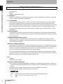
z Signal Words Used in This Manual
The following signal words and symbols are used in this manual to indicate precautions that must be observed
to ensure safe use of the V750-series Reader/Writer Unit. The precautions provided here contain important
safety information. You must observe these precautions.
The following signal words and symbols are used in this manual.
WARNING
CAUTION
Indicates a potentially hazardous situation which, if not avoided, will result in minor or
moderate injury, or may result in serious injury or death. Additionally there may be
significant property damage.
Indicates a potentially hazardous situation which, if not avoided, may result in minor
or moderate injury or in property damage.
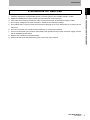
z Meanings of Alert Symbols
General Caution
Indicates general cautionary, warning, or danger level information.
Electrical Shock Caution
Indicates possibility of electric shock under specific conditions.
General Prohibition
Indicates a general prohibition.
Disassembly Prohibition
Indicates that disassembly is prohibited to prevent electric shock.
General Mandatory Action
Indicates a general action that must be performed by the user.
Ensure to establish a solid grounding
A label indicating that a device with a grounding terminal should always be grounded.
4
UHF RFID System
User's Manual
Introduction
Introduction
z Warnings
WARNING
READ AND UNDERSTAND THIS DOCUMENT
Never attempt to disassemble any Units while power is being supplied. Doing so may result in
serious electrical shock or electrocution.
Never touch any of the terminals while power is being supplied. Doing so may result in
serious electrical shock or electrocution.
This Product is not designed or rated for ensuring safety of persons. Do not use it for such
purposes.
UHF RFID System
User's Manual
5
Introduction
Introduction
Regulatory Compliance
1. EMC
READ AND UNDERSTAND THIS DOCUMENT
47 CFR, Part 15
RSS210
COFETEL: RCPOMV708-0153
FCC WARNING
Changes or modifications not expressly approved by the party responsible for compliance could void
the user's authority to operate the equipment.
FCC COMPLIANCE
This equipment complies with Part 15 of the FCC rules for intentional radiators and Class A digital
devices when installed and used in accordance with the operation manual. Following these rules
provides reasonable protection against harmful interference from equipment operated in a commercial
area. This equipment should not be installed in a residential area as it can radiate radio frequency
energy that could interfere with radio communications, a situation the user would have to fix at their
own expense.
COFETEL WARNING
This equipment operates on a secondary basis and, consequently, must accept harmful interference,
including from station of the same kind, and may not cause harmful interference to systems operating
on a primary basis.
EQUIPMENT MODIFICATION CAUTION
Equipment changes or modifications not expressly approved by OMRON Corporation, the party
responsible for FCC compliance, could void the user's authority to operate the equipment and could
create a hazardous condition.
IMPORTANT USER INFORMATION
This equipment complies with FCC radiation exposure limits set forth for uncontrolled equipment and
meets the FCC radio frequency (RF) Exposure Guidelines in Supplement C to OET65. This equipment
should be installed and operated with at least 23cm (9.1in) and more between the radiator and
person's body (excluding extremities: hands, wrists, feet and legs).
This device complies with RSS-Gen of IC Rules. Operation is subject to the following two conditions:
(1) this device may not cause interference, and (2) this device must accept any interference, including
interference that may cause undesired operation of this device.
2. Safety
UL 60950
Can/CSA C22.2 No 60950
IMPORTANT USER INFORMATION
(1) For products numbered with 0001X06 to 0048X06, only AC adapter complies with UL 60950. For
products numbered with 0049X06 or later, AC adapter and the V750 Reader/Writer comply with UL
60950.
(2) Products numbered with 0341308 or later comply with COFETEL certification.
(3) Product number consists of following data of seven digits.
AAAA B CC
6
AAAA
:Serial number. 0001 to 9999. (except for specially specified product)
B
:Month, 1 to 9, X, Y, and Z; X=10, Y=11, Z=12
CC
:Year
UHF RFID System
User's Manual
Introduction
Introduction
Precautions for Safe Use
Be sure to observe the following precautions to ensure safe use of the Product.
READ AND UNDERSTAND THIS DOCUMENT
1. Locations exposed to any flammable gasses, corrosive gasses, dust, metallic powder, or salts
2. Tighten the Backplane mounting screws and terminal block screws securely.
3. If any cable has a locking mechanism, make sure that it has been locked before using the cable.
4. Do not apply voltages to the input terminals in excess of the rated input voltage.
5. Do not allow water or wires to enter the Product through gaps in the case. Otherwise, fire or electric shock
may occur.
6. Turn OFF the power to the Product before attaching or removing an Antenna.
7. If an error is detected in the Product, immediately stop operation and turn OFF the power supply. Consult
with an OMRON representative.
8. Dispose of the Product as industrial waste.
9. Observe all warnings and precautions given in the body of this manual.
UHF RFID System
User's Manual
7
Introduction
Introduction
Precautions for Correct Use
Always observe the following precautions to prevent operation failure, malfunctions, and adverse effects on
READ AND UNDERSTAND THIS DOCUMENT
performance and equipment.
1. Do not use non-waterproof Products in an environment where mist is present. (For Reader/Writer and
normal type Antennas)
2. Do not expose the Products to chemicals that adversely affect the Product materials.
3. The transmission distance will be reduced if the front and back panels are mistakenly reversed and the
Unit is mounted to a metallic surface.
4. The transmission distance will be reduced when the Unit is not mounted to a metallic surface.
5. RF Tag cannot be washed the high temperature.
6. Do not drop the device you may receive major shocks. Doing so may result in personal injury or device
damage.
7. Do not apply strong force to, or place heavy items on the device or cables. Doing so may deform or
damage the device, resulting in electric shock or fire.
8. Use and store the product in an environment that is specified in the catalog or User’s manual. Failure to do
so may cause failure of the device, electric shock, or fire.
9. When transporting the Units, use special packing boxes.
10. Be careful not to apply excessive vibration or shock, or not to expose to water during transportation and
not to drop the product.
11. Provide an enough space around the device for ventilation.
12. Be sure to use wiring cable of the specified size for wiring. Failure to do so may cause failure of the device,
electric shock, or fire.
13. AC adaptor of the attachment is used without fail. Failure to do so may cause failure of the device, electric
shock, or fire.
14. After the DC connector side is connected, the AC100V side is connected when the AC adaptor is
connected. Failure to do so may cause failure of the device, electric shock.
15. The product uses a publicly available ISM frequency band of 902-928MHz to communicate with Tags.
Some transceivers, motors, monitoring devices, power supplies, and other similar RFID systems may
generate noise, which cause radio interference and may affect communication with Tags. If the product is
required in the vicinity of these items, check for any interferences prior to use.
Observe the following precautions to minimize the effects of normal noise.
(1) Ground the ground terminal on the Product and all metal objects in the vicinity of the Product to 100 Ω
or less.
(2) Do not use the Product near high-voltage or high-current lines.
16. Do not allow the device or cables to be exposed to water. Doing so may result in electric shock, fire or
failure of non-waterproof devices or cables.
17. Do not use damaged cables. Continued use of the damaged cables may result in electric shock or fire.
18. It is not possible to connect it with Reader/Writer excluding the specified antenna.
19. Be sure that all the mounting screws, terminal screws, and cable connector screws are tightened to the
torque specified in the relevant manuals.Incorrect tightening torque may result in malfunction.
8
UHF RFID System
User's Manual
Introduction
Introduction
Storage
Do not store the Product in the following locations.
• Locations exposed to corrosive gases, dust, metallic powder, or salts
READ AND UNDERSTAND THIS DOCUMENT
• Locations not within the specified operating temperature range
• Locations subject to rapid changes in temperature or condensation
• Locations not within the specified storage humidity range
• Locations subject to direct vibration or shock outside the specified ranges
• Locations subject to spray of water, oil, or chemicals
Cleaning
• Do not clean the Products with paint thinner or the equivalent. Paint thinner, benzene, acetone, and
kerosene or the equivalent will dissolve the resin materials and case coating.
UHF RFID System
User's Manual
9
Introduction
Introduction
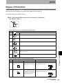
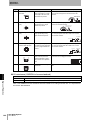
Meanings of Symbols
10
Meanings of Symbols
Indicates particularly important points related to a function, including precautions and application advice.
Indicates page numbers containing relevant information.
Indicates reference to helpful information and explanations for difficult terminology.
UHF RFID System
User's Manual
Introduction
Introduction
Table of Contents
Introduction
1
READ AND UNDERSTAND THIS DOCUMENT
2
Safety Precautions
4
Regulatory Compliance
6
Precautions for Safe Use
7
Precautions for Correct Use
8
Meanings of Symbols
10
Table of Contents
11
Features and System Configuration
13
Features
14
System Configuration
16
Specifications and Performance
19
Reader
20
Antenna
25
Specifications
28
Gen2 Tags Memory Map
32
Mode and Function
35
Mode
36
Function
37
Diagnosis and Maintenance
49
Connection of Reader and each equipment
50
Reader/Writer Setting
51
Installation Environment
52
Installation and Wiring
53
Wiring for cable
55
UHF RFID System
User's Manual
11
Introduction
Introduction
Command Line Interface
Control method
60
Communication Sequence
61
Command/Response Format
66
Communication Command
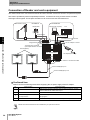
76
Communication command (Exclusive commands for secure tag)
89
Setting Command
101
Control Command
119
Undefined Command
128
Browser-Based Interface
129
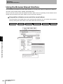
Using the Browser-Based Interface
130
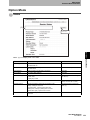
Option Mode
131
Safe Mode
145
Troubleshooting Alarms and Errors
147
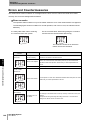
Errors and Countermeasures
148
Maintenance and Inspection
151
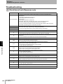
Troubleshooting
152
Reference data
153
Communications Time
154
Receiving Level Detection
157
Appendices
159
Accessory
160
Degree of Protection
161
Revision History
12
59
UHF RFID System
User's Manual
164
SECTION 1
SECTION 1
Features and System Configuration
14
System Configuration
16
UHF RFID System
User's Manual
Features and System Configuration
Features
13
SECTION 1
Features and System Configuration
Features
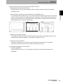
The OMRON V750 RFID Reader (herein after denoted as the reader) uses RFID (radio frequency
SECTION 1
identification) technology to read data stored on RFID tags.
The reader supports UHF (ultra high frequency) antennas, which are available separately. The reader
receives tag data through the UHF antenna and transfers data to a remote computer over a network
Features
connection.
Main Features
(1) Well-tuned communication performance and functions for customers' applications
1) Selective communication modes for various applications
Single access mode: reads a tag in high speed if there is a single tag in the communication field.
Multi access mode: optimizes a sequence automatically according to the number of tags existing in
the communication field.
2) Various communication condition setting
Multiple communication conditions suit user's optional usage.
Low power
High power
Low power
3) Self-operation function
Using two function; command entry function and programmable output function, the reader can
implement simple judgment or processing without instruction from the host.
-Command entry
Can set a command so that the command starts when power is turned on or input terminal signal
is on.
-Programmable output
4 outputs can be used for output terminals to show reader status or communication results. When
the output terminal is used for communication results, the result conditions can be set by
choosing criteria objective such as data value or tag count.
PC䋺Data collection
Ethernet
14
UHF RFID System
User's Manual
SECTION 1
Features and System Configuration
(2) Rich maintenance functions and on-site verification functions
1) Monitoring and setting via Web browser.
Via Web browser, you can get an operation status or setting conditions and set the operation
SECTION 1
parameters easily.
2) Communication monitoring function that reduces the installation time
for each channel), and an error logging function are equipped. These functions show the status of
radio waves and enable you to verify performance of tag-reader or analyze phenomena that may
change depending on on-site RF environment.
Features
A tag communication testing function, an on-site environmental monitoring function (a noise check
3) Multiple LED operation displays
The multiple LED indicators show the reader operation status clearly and simply so that you can
understand the status and handle an error quickly if it happens to occur.
4) Automatic antenna detection
This function enables you to check the connection status of antennas when a command is
executed. It helps to detect an error or problem of antenna(s) or wiring.
(3) Expandability applicable to broad usage
Firmware upgradable
Via Web browser on the PC, you can upgrade its firmware. It means that the functions are
expandable.
UHF RFID System
User's Manual
15
SECTION 1
Features and System Configuration
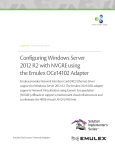
System Configuration
System example for logistic tracking application
SECTION 1
V750-series Radio wave propagative RFID system is ideal for long range communication and for the
system construction used in the production process or distribution control.
It is designed to have "High read range", "Quick response" and "Simple operation".
System Configuration
Net work
PC
PLC
RS-232C
Ethernet
V750 Reader/Writer
Dock door
system
V750 Reader/Writer
Conveyor
system
Multiple readers and antennas located in proximity or other UHF readers and antennas at neighborhood may cause
intereferences for detoriating communication performance. Please check your operating environmental before you start
to use.
16
UHF RFID System
User's Manual
SECTION 1
Features and System Configuration
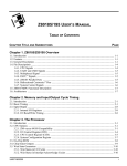
System Configuration
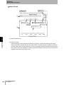
Max.imum 4 antennas can be connected to the reader. Sensor input can be applied to external inputs
external outputs for controlling such as indicators or buzzer according to its communication results.
I/O Device
Host Device
Lamp/Buzzer
PC(Personal computer)
System Configuration
Photoelectric sensor
SECTION 1
at the reader as a trigger input for starting communication with the tag, and then it can output to its
PLC
Digital Output
Ethernet or RS-232C
Digital Input
RF Tag
V750 Reader/Writer
AC Adaptor(Accessory)
Antenna #2
Antenna #1
Antenna Cable(Option)
Cable Length: 3m or 10m or 20m
Four antennas
or less can be
connected.
Antenna #4
Antenna #3
UHF RFID System
User's Manual
17
SECTION 1
Features and System Configuration
MEMO
SECTION 1
System Configuration
18
UHF RFID System
User's Manual
SECTION 2
Specifications and Performance
SECTION 2
20
Antenna
25
Specifications
28
Gen2 Tags Memory Map
32
UHF RFID System
User's Manual
Specifications and Performance
Reader
19
SECTION 2
Specifications and Performance
Reader
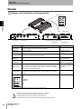
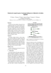
Names and Functions of Components
Status Indicators
SECTION 2
Reader
Mode switch
Control port
Antenna port
DC Power input
Ethernet port
RS-232C port
Name
Function
Connector specifications
Antenna port
[ANT1-ANT4]
Connects with UHF mono-static type antenna specified by OMRON via
antenna cables.Max 4 antennas can be connected to.
Reverse TNC
Control port
[CTRL PORT]
For future expansion.
Exclusive connector
DC Power input
[POWER DC12V]
Connects with the attachment AC adaptor to receive +12V electric power.*
Extension of AC adaptor cable is not allowable.
Exclusive connector
RS-232C port
[RS-232C]
Connects with the host via a commercially available RS-232C cable for DOS/V D-sub 9pin (male)
PC.
Inch screw (#4-40)
Ethernet port
[ETHERNET]
Connects with the host via a commercially available 10/100Base-T cable.
RJ-45
LED Left: Link, Right: Act
Input/Output port
[IN 1,2,3,4,C]
[OUT 1,2,3,4,C]
Connects to the input/output signal cable(s) via an attached I/O port adapter
(MC 1,5/10-STF-3,81).4 Inputs: connects with the sensor that works as a
trigger signal for communication start.4 Outputs: connects with the light or
actuator that is driven by output signal.
MC 1,5/10-GF-3.81
(produced by PHOENIX
CONTACT).
Mode switch
(Not indicated)
Pushing this button for 1 second or more makes the system rebooting with
default setting, which will be functional in case of system error or setting
unknown.
---
Status Indicators
PWR:
RUN:
ERR:
NORM/ERC:
ANTENNA:
IN:
OUT:
----
㪧㪮㪩 㪩㪬㪥 㪜㪩㪩 㪥㪦㪩㪤
㪆㪜㪩㪚
㪈
㪘㪥㪫㪜㪥㪥㪘
㪉
㪊
㪋
㪠㪥
㪈
㪉
㪊
㪋
㪦㪬㪫
Note: The high-speed mode cannot be used by the controller's setting.
• Antennas other than V740-HS01CA/HS01LA cannot be connected.
• The antenna cable must use an optional special antenna cable.
• The AC adaptor must use the AC adaptor of the attachment.
• The external I/O connector must use the terminal stand plug of the attachment.
20
Input/Output port
UHF RFID System
User's Manual
SECTION 2
Specifications and Performance
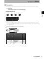
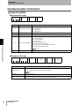
Connectors
Pin number for each connectors represents its pin allocation from the external view of the reader.
(1) Antenna Port
The antenna port is used to connect the antenna cable.
SECTION 2
Connector:Reverse TNC
ANT1
ANT2
ANT4
Reader
Name
ANT3
Function
SG
Signal output
GND
Ground
(2) RS-232C Interface
This port is used to connect the reader to the host containing RS-232C interface such as PC or
PLC (Programmable logic controller). If you use the PC as a host, prepare a cross cable to connect
the PC to the port.
Connector: D-sub 9pin (male), inch screw (#4-40)
㪈
㪌
㪐
㪍
Pin No.
Name
Function
I/O
1
---
---
---
2
RD
Receive Data
IN
3
SD
Send Data
OUT
4
---
---
---
5
SG
Signal Ground
---
6
---
---
---
7
RS
Request to Send
8
CS
Clear to Send
IN
9
---
---
---
OUT
UHF RFID System
User's Manual
21
SECTION 2
Specifications and Performance
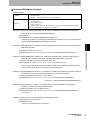
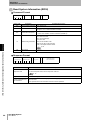
(3) Ethernet Interface
This port is used to connect the host to the reader via Ethernet. To connect them, use the
commercial cable 10/10Base-T.
Connector: RJ-45 (8 pin)
LINK LED
LED: Link (green) /Act (orange)
ACT LED
SECTION 2
Reader
Pin No.
Name
Function
I/O
1
TXD(+)
Transmit Data +
OUT
2
TXD(-)
Transmit Data -
OUT
3
RXD(-)
Receive Data -
IN
4
Not used
Reserved
---
5
Not used
Reserved
---
6
RXD(+)
Receive Data +
IN
7
Not used
Reserved
---
8
Not used
Reserved
---
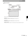
(4) I/O Interface
As an input/output port, the reader contains a terminal block of which connector is removable with
screws.
Terminal block connector: MC 1,5/10-STF-3,81 (produced by PHOENIX CONTACT)
Cable fixing screws x 10
Screw hole
Screw hole
Terminal stand plug
of attachment
22
Pin No.
Name
1
OUT1
Output port#1
OUT
2
OUT2
Output port#2
OUT
3
OUT3
Output port#3
OUT
4
OUT4
Output port#4
OUT
5
OUT_COM
6
IN1
I/O
Output common port
---
Input port#1
IN
7
IN2
Input port#2
IN
8
IN3
Input port#3
IN
9
IN4
Input port#4
IN
10
IN_COM
Input common port
---
UHF RFID System
User's Manual
Function
SECTION 2
Specifications and Performance
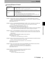
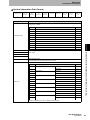
(5) Status Indicators
SECTION 2
Name
Color
Status
Reader
Indicator
Meaning
PWR
Power
Green
ON
Normally energized.
RUN
Running
Green
ON
Normally running.
Flashing
(Short interval)*
Boot processing
Flashing
(Long interval)**
Safe Mode running
ON
System error.The error has occurred and it stopped the
system operation.
ex. System error
Flashing
(Short Interval)*
Setting error.The error has occurred and it stopped by
settings.
ex. Power shut down in command communication
ex. Communication setting error
ex. Disconnection to the DHCP server
Flashing
(Long interval)**
Waiting for network connection.
ERR
Reader error
Red
RUN indicator off
:Unrecoverable error
RUN indicator on
:Recoverable error
NORM/
ERC
Communication result
:Normal end
Green
ON
Command executed or communication with tag completed
normally.
(Turns off after 50ms ON or upon ERR LED turns on.)
Communication result
:Error of Communication
Red
ON
Command executed or communication with tag completed
abnormally.
(Turn off after 50ms ON or upon NORM LED turns on.)
Antenna port #1
Orange
ON
Communication process is running via antenna #1.When
connecting with an antenna via antenna #1 is detected
after power turns on, it lights for 50ms.
Antenna port #2
Orange
ON
Communication process is running via antenna #2.When
connecting with an antenna via antenna #2 is detected
after power turns on, it lights for 50ms.
Antenna port #3
Orange
ON
Communication process is running via antenna #3.When
connecting with an antenna via antenna #3 is detected
after power turns on, it lights for 50ms.
Antenna port #4
Orange
ON
Communication process is running via antenna #4.When
connecting with an antenna via antenna #4 is detected
after power turns on, it lights for 50ms.
1
Input port #1
Green
ON
Signal of input port #1 is on
2
Input port #2
Green
ON
Signal of input port #2 is on
3
Input port #3
Green
ON
Signal of input port #3 is on
4
Input port #4
Green
ON
Signal of input port #4 is on
1
Output port #1
Green
ON
Signal of output port #1 is on
2
Output port #2
Green
ON
Signal of output port #2 is on
3
Output port #3
Green
ON
Signal of output port #3 is on
4
Output port #4
Green
ON
Signal of output port #4 is on
Antenna Port
1
2
3
Output Port
Input Port
4
* Short interval: approx. 500ms cycle (On: 250ms, Off: 250ms)
** Long interval: approx. 3000ms cycle (On: 1500ms, Off: 1500ms)
UHF RFID System
User's Manual
23
SECTION 2
Specifications and Performance
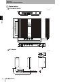
Demensions
V750-BA50C04-US
(Unit:mm)
215
Reader
152.4 (6 inch)±0.3
SECTION 2
Four-4.8 dia.
2.5
39
43.5
234.95 (9.25inch)±0.3
246
AC Adapter
35±1
(Unit:mm)
128±1
51.5±1
110±20
1200±50
24
UHF RFID System
User's Manual
SECTION 2
Specifications and Performance
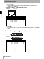
Antenna
Name of each part
V740-HS01CA/V740-HS01LA
O
M
R
O
N
SECTION 2
Antenna
Mounting Hole
The number of Mounting Hole is
about surrounding four.
N-Female connector
For connection with Antenna Cable.
Connector
Name
N-Female connector
Function
Antenna cable is connected with the connector.
UHF RFID System
User's Manual
25
SECTION 2
Specifications and Performance
Demensions
V740-HS01CA/V740-HS01LA
66±0.2
+1
57 0
84.5±0.2
Antenna
300+10
0
10.5
235±0.2
84.5±0.2
66±0.2
256 +3
-1
SECTION 2
26
84.5±0.2
84±0.2
10.5
256+3
-1
UHF RFID System
User's Manual
Mounting Hole
8-6.2 dia.
SECTION 2
Specifications and Performance
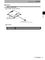
Antenna Cable
Demensions
Item
model
length(L1)
V740-A01 3M
å`V740-A01 10M
V740-A01 20M
3000±30(mm)
10000±250(mm)
20000±250(mm)
Shrinkage tube
SECTION 2
• V740-A01 3M
Shrinkage tube
3D-2V(Black)
Label
(38)
29.1
Antenna
V740-A01 3m
LOT No.xxxxx
21 dia.
16 dia.
(50)
17.4
3,000±30mm
• V740-A01 10M
Shrinkage tube
Shrinkage tube
3D-2V(Black)
Label
V740-A01 10m
LOT No.xxxxx
21 dia.
(38)
29.1
16 dia.
(50)
17.4
10,000±250mm
• V740-A01 20M
Shrinkage tube
Shrinkage tube
3D-2V(Black)
Label
V740-A01 20m
LOT No.xxxxx
21 dia.
(38)
29.1
16 dia.
(50)
17.4
20,000±250mm
Do not bend antenna cable by force. It could be a cause of beraking a wire.
• Always use V740-A01 3M/10M/20M anntena cable
• Do not change cable length of antenna cable.
• The antenna connector(TNC-typpe and N-type) are not water-proof.
• In case there are possibility to drop of water at anntenas and antenna cables, use water-proof tape at the connector
connection portion.
UHF RFID System
User's Manual
27
SECTION 2
Specifications and Performance
Specifications
General Specifications
Reader/Writer(V750-BA50C04-US)
Item
SECTION 2
Power supply
voltage
Specification
Reader
12 VDC, via attached AC Adapter.(Less than 28W)
AC Adapter
100 to 240 VAC 50/60Hz (0.5 A at 120 V)
Power consumption
28 W max.
Specifications
Ambient operating temperature
-10 to 50°C(with no icing)
Ambient storage temperature
25% to 85%(with no condensation)
Ambient storage temperature
-25 to 65°C(with no icing)
Insulation resistance
20 MΩ min. (at 100 VDC mega) between connector terminals and case
Dielectric strength
1,000 VAC, 50/60 Hz for 1 min between connector terminals and case
Dielectric strength
10 to 150 Hz, 0.2-mm double amplitude, acceleration: 10 sweeps in each of 3 axis directions
(up/down, left/right, and forward/backward) for 8 minutes each
Shock resistance
150 m/s2, 3 times each in 6 directions (Total: 18 times)
Dimensions
246 × 215 × 43.5 mm (W × H × D)
Degree of protection
IP50(IEC60529)
Antenna Connections
4 channels
Case material
Aluminum
Mounting
4 point screw(M4)
Tightening torque
1.2 N⋅m
Weight
Approx. 1,400 g
Normal type Antennas(V740-HS01CA/V740-HS01LA)
Item
Specification
Ambient operating temperature -15 to 60°C(with no icing)
Ambient storage temperature
25% to 85%(with no condensation)
Ambient storage temperature
-25 to 65°C(with no icing)
Insulation resistance
20 MΩ min. (at 100 VDC mega) between connector terminals and case
Dielectric strength
1,000 VAC, 50/60 Hz for 1 min between connector terminals and case
Dielectric strength
10 to 150 Hz, 0.7-mm double amplitude, acceleration: 10 sweeps in each of 3 axis directions
(up/down, left/right, and forward/backward) for 8 minutes each
28
Shock resistance
150 m/s2, 3 times each in 6 directions (Total: 18 times)
Dimensions
256 × 256 × 57 mm (W × H × D) (excluding Cable)
Degree of protection
IP53(IEC60529)
Antenna Connections
4 channels
Material
Case: PVC, Base Panel: Aluminum
Mounting
4 point screw(M6)
Tightening torque
2 N⋅m
Weight
Approx. 800 g
UHF RFID System
User's Manual
SECTION 2
Specifications and Performance
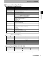
Communications Specifications
Reader/Writer(V750-BA50C04-US)
Item
Specification
EPC global Class1 Generation 2 (C1G2)
UHF operating frequency
902.75-927.25MHz
FHSS (Frequency Hopping Spread Spectrum) 50ch
Antenna output
30dBm, 4W EIRP (Changeable for each antennas.)
Connected antenna(s)
V740 Series UHF Antenna x 4 ports
(V740-HS01CA or V740-HS01LA)
Control method
V750 original command/response
Control port
Ethernet
Supported standard: IEEE802.3 compliance (10Base-T)
IEEE802.3u compliance (100Base-TX)
Supported protocol: TCP/IP Port:7090 (Changeable)
SECTION 2
Supported tag
Specifications
RS-232C
Supported standard: RS-232C compliance
Baud rate: 9.6 / 19.2 / 38.4 /57.6 kbps
Data length: 7 / 8 bits
Parity: Even / Odd / None
Stop bit: 1 / 2 bit
Browser interface
Ethernet
Protocol: HTTP Port:80 (Fixed)
TCP/IP Port:7091 (Changeable)
Digital Input/Output
4 Inputs
4 Outputs
Status indicator
8 Operation status
(POWER, RUN, ERR, NORM/ERC, ANTENNA1-4)
4 Inputstatus
4 Output status
Self diagnostic function
(1) CPU operation check
(2) Antenna connecting check
(3) Communication error detection with tags
Scalability
(1) Software upgradable
(2) Antenna control port
Antennas(V740-HS01CA/HS01LA)
Item
Specification
V740-HS01CA
V740-HS01LA
Circular
Linear
Polarization
Operating frequency
902-928 MHz
Gain
6 dBi max.
50 Ω
Impedance
V.S.W.R
< 1.5 : 1
Maximum Input Electric power
1W
Antenna Cables(V740-A01 3M / 10M / 20M)
Item
Specification
V740-A01 3M
Insertion Loss
Cable Type
V740-A01 10M
V740-A01 20M
1.5 dB min.
3D-2V
3.0 dB min.
5D-SFA
Note: Cable Loss for V740-A01 20M cable is about 3.0dB, and communication range was reduced
about 80% compare to the 3m and 10m cables
UHF RFID System
User's Manual
29
SECTION 2
Specifications and Performance
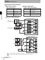
External I/O Specifications
Input Specifications
Output Specifications
(IN1, IN2, IN3, IN4)
Item
(OUT1, OUT2, OUT3, OUT4)
Specifications
Item
Specifications
Output method
Open collector output
(Sync type: NPN)
Input voltage
10.2 to 26.4 VDC
(including ripple)
Output maximum level
26.4 VDC
(including ripple)
Input impedance
2.35 kΩ TYP.
Leakage current
10μA max.
Input current
4.5 mA TYP.(24VDC)
9.8 mA TYP.(24VDC)
Residual voltage
3 V max.(When output level is 13 mA)
2 V max.(When output level is 10 mA)
I/O Device Wiring Example
Reader/Writer Input Section
NPN Transistor
Open-collector Output
(e.g., from a 3-wire Sensor)
Outputs
IN1
Internal
circuits
Specifications
Photo coupler
Sensor internal
circuits
SECTION 2
Input method
0V
IN2
Internal
circuits
+V
24 VDC
power supply
Internal
circuits
IN3
Device with contact
(e.g., pushbutton switch)
Internal
circuits
IN4
COM
Fuse
Reader/Writer Output Section
Fuse
Internal
circuits
OUT1
Relay
Internal
circuits
OUT2
Relay
Internal
circuits
OUT3
24 VDC
power supply
Internal
circuits
OUT4
COM
Fuse
• Do not apply the over rated voltage to the input terminals.
• Do not connect the over voltage for its maximum rateing or load to the output terminals.
30
UHF RFID System
User's Manual
SECTION 2
Specifications and Performance
Host communications specifications
The reader can operate with Ethernet or RS-232C serial communiction from host computer or system.
Ethernet
Item
Specification
IEEE802.3 compliance (10Base-T)
IEEE802.3u compliance (100Base-TX)
Protocol
TCP/IP
Port
TCP/IP Port: 7090, HTTP Port: 80
Cable length
Marketed range
SECTION 2
Conforming standard
Specifications
RS-232C
Item
Specification
Conforming standard
RS-232C compliance
Baud rate
9,600 bps, 19,200 bps, 38,400 bps, 57,600 bps
Data length
7/8 bits
Parity
Even/Odd/None
Stop bit
1/2 bit
Cable length
15m max.
• The length of communication cable may influnces on maxium transmission rate. Please check before operation.
UHF RFID System
User's Manual
31
SECTION 2
Specifications and Performance
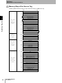
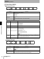
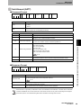
Gen2 Tags Memory Map
Gen2 Tags Memory Map
GEN2 tags have four memory banks.
Kill Password and Access Password are stored in bank 00 (Reserved Area), EPC code is in bank 01
(EPC Area), Tag Identification Memory data that is read only is in bank 10 (TID Area). User data is in
SECTION 2
bank 11 (User Area). For the detailed information refer each tag's specification.
MSB
LSB
1F0h
Memory Bank3
1FFh
Gen2 Tags Memory Map
:
:
50h
5Fh
40h
4Fh
30h
3Fh
USER
20h
2Fh
Area
10h
1Fh
00h
0Fh
Bank 11
Memory Bank2
30h
Bank 10
20h
3Fh
Tag and Vender Specified Data (ex. Tag Serial Number)
2Fh
TID
10h
Tag Identification Memory data
1Fh
Area
00h
Tag Identification Memory data
0Fh
Memory Bank1
Bank 01
100h
EPC [15 : 0]
F0h
EPC [31 : 16]
FFh
E0h
EPC [47 : 32]
EFh
EPC
D0h
EPC[ 63 : 48]
DFh
Area
:
:
:
20h
EPC [239 : 224]
2Fh
10h
PC(Protocol Control) (SeeNote 1)
1Fh
00h
CRC-16 (SeeNote 2)
0Fh
Memory Bank0
10Fh
Bank 00
Password
30h
ACCESS Password [15 : 0]
3Fh
20h
ACCESS Password [31 : 16]
2Fh
&
10h
KILL Password [15 : 0]
1Fh
Reserved Area
00h
KILL Password [31 : 16]
0Fh
Note 1: Details of PC(Protocol Control)
10
11
12
13
PC + EPC length
16 × (n+1)
14
15
16
RFU
17
0 : EPC
1 : AFI
18
19
1A
1B
1C
1D
1E
1F
Data
Note 2: CRC16 calculated and stored at the time the tag chip memory powering-up with the data of
PC+EPC(only specified length) value.
• Please check before operation when using the other manufacurere tag which comply with EPC global Class1
Generation2(ISO/IEC18000-6 TypeC). Also please refer the memory map specification provided from the IC chip
manufacturer.
32
UHF RFID System
User's Manual
SECTION 2
Specifications and Performance
Memory Map of the Gen2 Tag(For Impinj Co. MONZA chip. )
Following table shows the memory map of the Gen2 tag(For Impinj Co. MONZA chip.)
Memory
Bank2
Bank 10
TID
MSB
LSB
Area
10h
Tag Identification Memory (Read only)
1Fh
32bit
00h
Tag Identification Memory (Read only)
0Fh
70h
EPC [15 : 0]
7Fh
60h
EPC [31 : 16]
6Fh
5Fh
50h
EPC [47 : 32]
40h
EPC [63 : 48]
4Fh
128bit
30h
EPC [79 : 64]
3Fh
20h
EPC [95 : 80]
2Fh
10h
PC(Protocol Control)
1Fh
00h
CRC-16
0Fh
Password
40h
(See Note 1)
4Fh
&
30h
ACCESS Password [15 : 0]
3Fh
Reserved Area
20h
ACCESS Password [31 : 16]
2Fh
80bit
10h
KILL Password [15 : 0]
1Fh
00h
KILL Password [31 : 16]
0Fh
Memory
Bank0
Bank 00
Gen2 Tags Memory Map
EPC
Area
SECTION 2
Memory
Bank1
Bank 01
Note 1 : 40h to 4Fh
40
41
42
43
44
45
46
47
48
49
4A
4B
4C
4D
4E
4F
FACTORY
SETTINGS
Lock Bits
Note 2 : Data Pointer and Data length in the Data Read(RDDT)/Data Write(WTDT) command format should
be specified by Decimal Number in each WORD(16bits) unit.
0
1
2
3
4
5
6
7
8
7
EPC [ 15 : 0 ]
6
EPC [ 31 : 16 ]
5
EPC [ 47 : 32 ]
4
EPC [ 63 : 48 ]
3
EPC [ 79 : 64 ]
2
EPC [ 95 : 80 ]
1
PC ( Protocol Control )
0
CRC-16
Data Pointer
9
A
B
C
D
E
F
In case data reading 32bits(2WORD) data on EPC[95 to 64bits] in the above me
RDDT 1 2 2 Memory Bank 1, Data Pointa 2, Data length 2
UHF RFID System
User's Manual
33
SECTION 2
Specifications and Performance
Memory Map of the Secure Tag
Following table shows the memory map of the secure tag (μ-HIBIKI Ver1.34).
MSB
5F0h
LSB
Block5 User [15 : 0]
5FFh
500h
Block5 User [255 : 240]
50Fh
4F0h
Block4 User [15 : 0]
4FFh
:
SECTION 2
:
Memory Bank 3
:
:
:
400h
Block4 User [255 240]
40Fh
3F0h
Block3 User [15 : 0]
3FFh
:
:
Gen2 Tags Memory Map
(Bank 11)
300h
Block3 User [255 : 240]
30Fh
USER memory
2F0h
Block2 User [15 : 0]
2FFh
200h
Block2 User [255 : 240]
20Fh
1F0h
Block1 User [15 : 0]
1FFh
100h
Block1 User [255 : 240]
10Fh
0F0h
Block0 User [15 : 0]
0FFh
(96word)
:
:
:
:
:
000h
:
USER [255 : 240]
00Fh
Memory Bank 2
(Bank 10)
030h
03Fh
TID memory
020h
02Fh
(4word)
010h
01Fh
000h
00Fh
Memory Bank 1
(Bank 01)
34
100h
EPC [15 : 0]
10Fh
0F0h
EPC [31: : 6]
0FFh
:
:
EPC memory
040h
EPC [207 : 192]
04Fh
(17word)
030h
EPC [223 : 208]
03Fh
020h
EPC [239 : 224]
02Fh
010h
PC [15 : 0]
01Fh
000h
CRC-16 [15 : 0]
00Fh
0F0h
RFU
0FFh
0E0h
RFU
0EFh
0D0h
Block5 User Password [15 : 0]
0DFh
0C0h
Block5 User Password [31 : 16]
0CFh
0B0h
Block4 User Password [15 : 0]
0BFh
Memory Bank 0
0A0h
Block4 User Password [31 : 16]
0AFh
(Bank 00)
090h
Block3 User Password [15 : 0]
09Fh
Reserved memory
080h
Block3 User Password [31 : 16]
08Fh
(16word)
070h
Block2 User Password [15 : 0]
07Fh
060h
Block2 User Password [31 : 16]
06Fh
050h
Block1 User Password [15 : 0]
05Fh
UHF RFID System
User's Manual
040h
Block1 User Password [31 : 16]
04Fh
030h
Access Password [15 : 0]
03Fh
020h
Access Password [31 : 16]
02Fh
010h
Kill Password [15 : 0]
01Fh
000h
Kill Password [31 : 16]
00Fh
SECTION 3
Mode and Function
36
Function
37
SECTION 3
Mode
Mode and Function
UHF RFID System
User's Manual
35
SECTION 3
Mode and Function
Mode
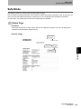
Reader Operating Mode
Reader operating mode contains three modes, Operation Mode, Safe Mode and Update Mode.
If you push the Mode Switch for 1 second or more and release the switch while the system is running,
or if the reader detects an error (ex. System error or a failure of firmware update), and it can not start
up normally due to this error, the reader will start up under Safe Mode. Under this mode, you can check
the status via Web browser, initialize the setting and install the firmware.
SECTION 3
Refer to the Ethernet Interface and RS-232C Interfacein detail.
p. 55
Start
Mode
Start with mode switch
Boot Process
Safe mode
Abnormality
Operation mode
Safe mode
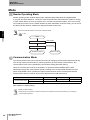
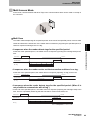
Communication Mode
The communication mode can be selected according to changing communication speed with RF tag
such as high-speed communication or reducing speed to get more reliably communcation. The
communication mode can be specified by comunication setting parameter (SETC).
When the communiction mode is set to MODE 0, it represents AUTO MODE that the reader
automtically change the communication speed according to the environmental interferences level.
When using MODE 2 which provides the highest communication speed, intereferences between
several readers will be increased, and cause to deteriorate the read performance.
RF Tag → Reader/Writer
Communication speed
Reader/Writer → RF Tag
Mode 0
Mode 1
Mode 2
Auto
40kbps
160kbps
40kbps
Note: MODE 0 is default setting.
• MODE 0 is default setting.
• Please test prior to operation to check the influences on interferences with several readers if you change the
communication speed fast.
36
UHF RFID System
User's Manual
SECTION 3
Mode and Function
Function
The reader consists of there parts of function, System I/F function for communication with host system or
controlling general input and output from external devices, control the reader device, and control the
communication with RF tag. As a function of controlling the reader device, it includes Command execution,
Self-execution, firmware update.
㪟㫆㫊㫋
㪧㪚
㩿㪧㪼㫉㫊㫆㫅㪸㫃㩷㪺㫆㫄㫇㫌㫋㪼㫉㪀
㪭㪎㪌㪇㩷㪩㪼㪸㪻㪼㫉㪆㪮㫉㫀㫋㪼㫉
㪩㪼㪸㪻㪼㫉㩷㪚㫆㫅㫋㫉㫆㫃㩷㪝㫌㫅㪺㫋㫀㫆㫅
㩷㩷㩷㪚㫆㫄㫄㪸㫅㪻㩷㪜㫏㪼㪺㫌㫋㫀㫆㫅
䇭㪈㪅㪚㫆㫄㫄㫌㫅㫀㪺㪸㫋㫀㫆㫅㩷㪺㫆㫄㫄㪸㫅㪻
㪩㪝㩷㪫㪸㪾
㪚㫆㫄㫄㫌㫅㫀㪺㪸㫋㫀㫆㫅㩷㪺㫆㫄㫄㪸㫅㪻
䊶㪚㫆㫄㫄㫌㫅㫀㪺㪸㫋㫀㫆㫅㩷㪤㫆㪻㪼
䇭㪪㫀㫅㪾㫃㪼㪆㪤㫌㫃㫋㫀㩷㪸㪺㪺㪼㫊㫊
SECTION 3
㪪㫐㫊㫋㪼㫄㩷㪠㪆㪝㩷㪝㫌㫅㪺㫋㫀㫆㫅
㩷㩷㩷㪚㫆㫄㫄㪸㫅㪻㩷㪠㪆㪝㩷㪝㫌㫅㪺㫋㫀㫆㫅
䇭㪈㪅㩷㪜㫋㪿㪼㫉㫅㪼㫋
㩷㩷㪉㪅㩷㪩㪪㪄㪉㪊㪉㪚
㩷㩷㪉㪅㪩㪼㪸㪻㪼㫉㩷㪺㫆㫅㫋㫉㫆㫃㩷㪺㫆㫄㫄㪸㫅㪻
㪧㪣㪚
㩷㩷㩷㪮㪼㪹㩷㪙㫉㫆㫎㫊㪼㫉㩷㪝㫌㫅㪺㫋㫀㫆㫅
㩷㩷㪜㫋㪿㪼㫉㫅㪼㫋
㪜㫏㫋㪼㫉㫅㪸㫃㩷㪠㫅㫇㫌㫋㩷㪦㫌㫋㫇㫌㫋
㩷㩷㩷㪪㪼㫃㪽㩷㪦㫇㪼㫉㪸㫋㫀㫆㫅
㩷㩷
㩷㩷㩷㪝㫀㫉㫄㫎㪸㫉㪼㩷㪬㫇㪻㪸㫋㪼
㪩㪼㪸㪻㪼㫉㩷㪺㫆㫅㫋㫉㫆㫃㩷㪺㫆㫄㫄㪸㫅㪻
㪩㪼㪸㪻㪼㫉㪆㪮㫉㫀㫋㪼㫉㩷㪪㪼㫋㫋㫀㫅㪾
㪚㫆㫄㫄㫌㫅㫀㪺㪸㫋㫀㫆㫅㩷㪺㫆㫅㪻㫀㫋㫀㫆㫅㩷㪪㪼㫋㫋㫀㫅㪾
Function
㩷㩷㩷㪛㫀㪾㫀㫋㪸㫃㩷㪠㫅㫇㫌㫋㪆㪦㫌㫋㫇㫌㫋
㪜㫏㫋㪼㫉㫅㪸㫃㩷㪠㫅㫇㫌㫋㩷㪦㫌㫋㫇㫌㫋㩷㪻㪼㫍㫀㪺㪼
㩷㩷㪊㪅㪤㪸㫀㫅㫋㪼㫅㪸㫅㪺㪼㩷㪺㫆㫄㫄㪸㫅㪻
㪤㪸㫀㫅㫋㪼㫅㪸㫅㪺㪼㩷㪺㫆㫄㫄㪸㫅㪻
㪠㫋㩷㫉㪼㪸㪻㫊㩷㫆㫉㩷㪺㪿㪸㫅㪾㪼㫊㩷㫆㫇㪼㫉㪸㫋㫀㫆㫅㩷
㪺㫆㫅㫋㫉㫆㫃㩷㫆㫉㩷㫊㪼㫋㫋㫀㫅㪾㩷㫆㪽㩷㫋㪿㪼㩷㫉㪼㪸㪻㪼㫉㪅
㩿㪜㫏㫋㪼㫉㫅㪸㫃㩷㪠㫅㫇㫌㫋㩷㪦㫌㫋㫇㫌㫋㩷㪺㫆㫅㫋㫉㫆㫃㪀
System I/F Function
The System I/F provides the command I/F for communication with host system and web browser I/F. It
also provides digital input/output I/F for controlling external input and output devices.
Command I/F Function
Via 10/100BaseT Ethernet or RS-232C, the host issues a command to control the reader. As the
control method, V750 supports original procedures. Same commands are used via Ethernet and RS232C.
PC
RS-232C Cable
RS-232C port
Either
Ethernet Cable
Ethernet port
PLC
Command
Response
UHF RFID System
User's Manual
37
SECTION 3
Mode and Function
• Ethernet
Ethernet is connected with the host such as server computer via TCP/IP protocol.
IP address corresponds to dynamic IP address assigned by DHCP server. You can choose the static IP
address (Default 192.168.1.200) or a dynamic IP address. Default setting is static IP address. The port
7090 is used by reader for communication. IP address and the port number (over 1024) can be
changed by using a setting command or Web page. If the reader can not detect the DHCP server
under dynamic IP address setting, it will flash the error indicator and start up with static IP address.
• RS-232C
To connect to the PC or PLC(Programmable Logic Controller) which equipped RS-232C serial
SECTION 3
Function
38
communiction I/F.
Following communication setting for RS-232C are supported.
Opptional communication conditions
Item
Setting value
Factory-default
Baud rate
9,600 bps, 19,200 bps, 38,400 bps, 57,600 bps
57,600 bps
Data length
7/8 bits
7 bit
Parity
Even/Odd/None
Even
Stop bit
1/2 bit
2 bit
UHF RFID System
User's Manual
SECTION 3
Mode and Function
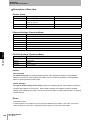
Web Browser Function
All the reader function can be accessed thorough the web browser which is installded on the standard
PC. It can open the operation windows by inputting the address http;//192.168.1.200(default). If you are
setting individual IP address for each readers, you need to input its IP address. The Java software
required to control the web browser I/F.
Refer to the Browser-Based Interface for details.
p. 129
SECTION 3
Function
Item
Web Browser
Function
Via Web browser, you can set following functions, which can perform various works such
as indicating an operation status or setting condition, or setting an operation parameter.
1.Reader Status
Indicates current setting and operation status
2.Reader Settings
Specifies a parameter for communication with host.
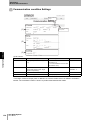
3.Communication Settings
Specifies a parameter for communication with tag.
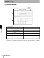
4.Operation Settings
Specifies a command entry and programmable output conditions.
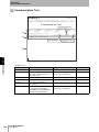
5.Communication Test
Executes a communication commands
6.Utility
Provides some functions for easy installation and maintenance.
- Latest Error Logging (The function to display the latest error log)
- History of Error Logging (The function to display the counted error log)
- Noise Check (The function to monitor an on-site environment)
- Option Information (The function to display the information of available options)
7.Firmware Update
Provides the method to update.
Note: You can download Java software via following URL.
http://www.java.com/ja/
Java(TM) is trademark of Sun Microsystems.
UHF RFID System
User's Manual
39
SECTION 3
Mode and Function
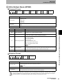
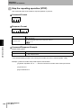
Digital Input/Output
• Digital input
Following two functions can be assigned to 4 digital inputs respectively. To assign the function, set via
Set Operation window of command or Web.
1. User Input
:reads ON/OFF state by receiving the command from the host.
2. Command entry
:executes registered command series at the rising edge of input signal.
• Digital output "Programmable output"
Following three functions can be assigned to 4 digital outputs respectively. To assign the function, set
SECTION 3
via Set Operation window of command or Web.
1. User output:
outputs ON/OFF state according to the command from the host.
Function
2. Reader state output:
outputs operation status of the reader.
Communication results output:outputs ON/OFF signal depending on the
specified judgment after communication process.
Refer to the Self-Operation for details.
p. 42
40
UHF RFID System
User's Manual
SECTION 3
Mode and Function
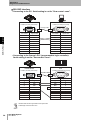
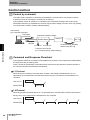
Reader control function
The function of control the reader device provides the interpretation of the command from the system I/
F to tag communication control, and vice versa.
Command Execution
Receiving a command from the host via Ethernet or RS-232C, the reader starts the command
execution and return its response(result) to the host. You can use following commands.
Refer to the Command Line Interface for details.
SECTION 3
p. 59
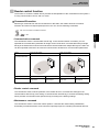
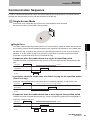
• Communication command
specified the communication parameter for single access mode which communicates with just single
RF tag in the field and for multi access mode which communicates with multiple RF tag in the field. You
can also specified anntenna to be used and communiction duration as a communication parameters.
Mode
Single Access Mode
Function
The command is used to communicate with RF tag. In the commmunication command, you can
Multi Access Mode
RF Tag in the
Communication field
Repeat
Once
Repeat
Once
Repeat
parameter
SOC
Single Once
SRP
Single Repeat
MOC
Multi Once
MRP
Multi Repeat
• Reader control command
The command is used to set the pramater of the reader device or communiction settings for the
communication with RF tag. As a setting of commmuniction with RF tag, it includes the filtering setting
which provides communiction with specific RF tag according to the filtering settings.
• Maintenance command
The command is used to control the reader opration. It includes the reader setting initilatization,
terminating command execution, and control the input/output port for controlling the external devices.
UHF RFID System
User's Manual
41
SECTION 3
Mode and Function
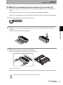
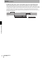
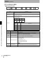
Self-Operation
The self-execution function provides the stand-alone solution to read RF tag and control the external
output according to the result of reading tags without host controller. The registered command can be
issued by triggerring external input such as sensors. The result of communiction or reader status can
be outputted to external ouput.
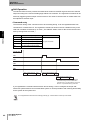
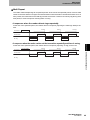
• Command entry
The execution timing of the command is at in each execting timing. It can be registered either from
command I/F or web brower I/F. The registered command is stored in the non-volatile memory in the
read and it enables at next boot-up or reset. ( The ON/OFF status of IN1 to IN4 can be read from the
SECTION 3
host by issuing EXIO command.)
Item
Executing timing
Function
Power On
Power up or TCP/IP connection
IN1
The rising edge of input #1 signal.
IN2
The rising edge of input #2 signal.
IN3
The rising edge of input #3 signal.
IN4
The rising edge of input #4 signal.
Entered command
Any given command
Power On
IN1
IN2
IN3
IN4
Start Entered command
End
process
at Start Up
process
Start Entered command End
process
at IN1
process
Start Entered command End
process
at IN2
process
The reader executes the IN2 registered
command during command execution.
It shows Error if you execute the command
which is not permitted during execution.
If you registered the command which execute at boot timing, it can be configure the simple self
instruction system without host communication system or can be possible to self checking functionality
for the system at the system boot.
Do not registered the Reset Command during powering-up. It causes failure of boot up of the reader.
42
UHF RFID System
User's Manual
SECTION 3
Mode and Function
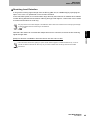
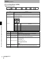
• Programmable output
The programmmable output can output the reader operation status such as normal or error results, or
judgement results based on comparison the response from the RF tag data.
It can use from both command I/F or web browzer I/F.
Available conditions
Function
Output timing
Note
Running Normally
Same action as RUN LED (except for blink).
Abnormally stopped
Same action as ERR LED (except for blink).
COM
Communication status
Same action as OR of AT1-4 LED.
ATn (n:1 to 4)
Antenna "n" is specified.
Same action as LED of AT1, AT2, AT3, and AT4.
The judgement results output to output port(OUT1 to OUT4) according to the judgement criteria which
registered in the reader at the timing when the RF tag is responeded. It can be specified two judgment
Available conditions
Function
Output timing
Condition setting
Function
criteria and output duration for each output. In case of no judgement criteria setting, it alwasy output.
SECTION 3
RUN
ERR
Option
NORMAL
The process is
finished normally.
-The read/written tag count:
Operator (>=, <=, ==, !=)
Compared number
-Data comparison: Operator (==, !=)
Compared data
Output duration
ERROR
The process is
finished abnormally.
Error code
Output duration
Refer to the Command Line Interface and Browser-Based Interface for details of a Setting method.
p. 59, p. 129
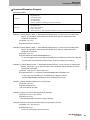
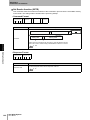
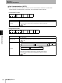
Firmware Update
You can update the firmware by specifying update files via Web browser. Updated data shall be
effective upon subsequent powering-up. If the firmware update is failed with some reasons and the
reader could not boot-up correctly, you can recover the reader by boot-up with Safe-mode.
Do not power down the reader during firware update. It cause of failure to boot the reader.
UHF RFID System
User's Manual
43
SECTION 3
Mode and Function
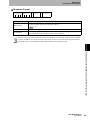
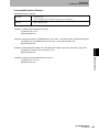
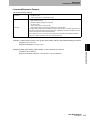
EPC Word Length
The function of setting EPC owrd length can be set by specifying the option "EWL" in the
communication setting command(SETC). It can also be read by the command(GETC) with the option
"EWL".
The EPC word length can be set/get thorugh the"Communication condition Settings" window in the "Comminction
condition setting" described at the SECTION 6
p. 134
The length shall be set with "0" as an auto mode or a number from 1 to 32 as fixed length mode.
SECTION 3
Default value is "0" (auto mode).
For fixed length mode, set a total number of tag's PC length (constantly 1) and EPC word length.
Value
Description
Function
0(auto mode)
R/W measures the EPC word length of the tag automatically and sets the most suitable
value. Generally, use this mode.
1 to 32(fixed length mode)
R/W communicates with the tag depending on the set value. If you have a word length of
the tag to be read before hand, use this mode.The value must be the greatest of the EPC
word lengths of the tags to be read.
Ex1) When EPC word length of a communicating tag is unknown set EPC word length to "0" (auto
mode).
[Tx] SETC ewl=0
[Rx] SETC0000
Ex2) When EPC word length of a communicating tag is known beforehand, set the word length.
For example, set it as follows when all EPC length of a communicating tag are 96bit (6 words).
[Tx] SETC ewl=7
[Rx] SETC0000
If the number of tags to be read is two or more and each tag has different EPC length, set the
greatest number of the EPC word lengths of them.
RF Tag A
㪜㪧㪚㪔㪍㩷㫎㫆㫉㪻㫊
RF Tag B
EPC=10 words
RF Tag C
EPC=4 words
Set it to 11 (PC 1 word and EPC 10 words)
[Tx] SETC ewl=11
[Rx] SETC0000
[Note] If you set the smaller value than the actual EPC word length, communication precision may be
decreased.
[Note] This function is available in firmware version 102-102-103-0 or later
44
UHF RFID System
User's Manual
SECTION 3
Mode and Function
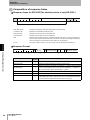
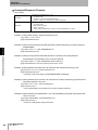
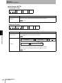
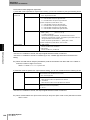
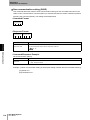
Receiving Level Detection
It can get the receiving signal strength from the RF tag (dBm unit, 0.125dBm step) by specifying the
option "LVL" in the "-tif" paraemeter on the ID read command.
In the UHF RFID system, the communication range varies by the influences of materials and condition
of which RF tag attached and orientation of RF tag and type of RF tags etc. This function can be useful
to measure these influnces on RF tag.
This graph of the communiction diagram in the Reference data at SECTION 8 shows the the receiving signal strength
vs distance between antenna and RF tag for the reference.
p. 157
signal strength value.
Please use these values which getting LVL option and its reference graph as a relative reaference only. It can not
Function
[Note] This function is available in firmware version 102-102-103-0 or later.
SECTION 3
Note that if the reader can communicate multiple times at one command, it returns the first receiving
gurantte the absorte value due the value may vary in variious condition such as RF tag used and sourrneded
environment.
UHF RFID System
User's Manual
45
SECTION 3
Mode and Function
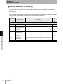
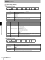
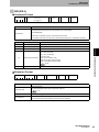
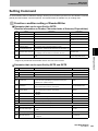
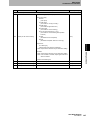
Session Setting
The session flag which described in the EPC Global Class 1 Generation 2 air interface standard
indicates the duration of keeping power-on after the RF tag chip is shutted down such as it comes out
from the antenna field.
It recommends to use as default settings in normal operation.
The default settings of the session flag are follows.
S0 for communication sequence specified once access ( SOC, MOC)
S2 for communication sequence specified repeat access ( SRP,MRP)
It can be settable based on the requirements of system operation.
Communication option
SECTION 3
Once Access Mode
- Single Once
- Multi Once
Flag
S0
Factory default setting.
In this setting, the reader communicates with all tags existing in the
communication field whenever a command is executed.
S1/S2/S3
In this setting, the reader communicates with un-read tags (it ignores onceread tags.)
If S1 is set, tag refreshes its S1 flag when a specified time has passed after
flag setting (after communication transaction) regardless of whether tag
energized or not. It means that the tags are read repeatedly in a certain
interval.
If S2 or S3 is set, tag refreshes its S2 or S3 flag when a specified time has
passed after tag energizing stopped. It means that the tag is not re-read unless
the tag stays out of the communication field for the specified time.
S2
Factory default setting.
In this setting, the reader communicates with new-detected tags existing in the
communication field during the command execution.
S0
When there is a tag the reader can not read because of flag conflict with other
readers, this setting enables the reader to read the tag.
S1/S3
If another reader set in the previous process line uses S2 flag, the reader same
flag may encounter the flag conflict. S1 and S3 flags are used to avoid this
conflict. Setting S3 provides same operation as S2 setting. If S1 is set, tag
refreshes its S1 flag when a specified time has passed after flag setting (after
communication transaction) regardless of whether tag energized or not. It
means that the tags are read repeatedly in a certain interval.
Function
Repeat Access Mode
- Single Repeat
- Multi Repeat
Description
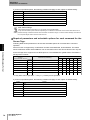
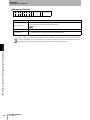
*1 : The read rate may drop when the session flag is set to S0 for the communiction seqeunce with
repeat(SRP/MRP), due the reader communcates with several times with the same RF tag and it
increase the communiction time. Also it may cause the reader halt error(system setting error) due
to the increase the data trafic on the communiction I/F on Ethernet or RS-232C.
Flag
S0
Effect of each session flag
None
S1
500ms to 5000ms (Same when tag is energized)
S2/S3
2000ms or more
[Reference : Class1 Generation2 UHF RFID Protocol for Communictions Version 1.1.0]
* SL flag which can be specified independetly with S0 to S3 is used for filtering function.
46
UHF RFID System
User's Manual
SECTION 3
Mode and Function
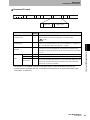
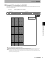
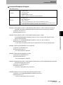
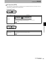
LBT(listen Before talk)
In the Japanese radio regulation, it needs to check the available channels before it outputs the radio
(LBT : Listen Before Talk) due to its limited channl usage.
LBT requirements (for high output)
Carrier sense level
: -74 dBm/channel
Carrier sense time
: above 5msec
transmitting duration
: transimit below 4msec, wait least 50msec.
The default setting is set to all channels (1 to 9 channel ) . It can also specify 1,3,5 channels for
example.
If you select only one channel and this channel is not available during timout period of the command,
Function
the reader returns the communication error ( code 7000 : channel are not available).
SECTION 3
It can select the transmitting channel either all channels or only specfied channels with LBT control.
UHF RFID System
User's Manual
47
SECTION 3
Mode and Function
MEMO
SECTION 3
Function
48
UHF RFID System
User's Manual
SECTION 4
Diagnosis and Maintenance
Reader/Writer Setting
51
Installation Environment
52
Installation and Wiring
53
Wiring for cable
55
UHF RFID System
User's Manual
Diagnosis and Maintenance
50
SECTION 4
Connection of Reader and each equipment
49
SECTION 4
Diagnosis and Maintenance
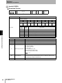
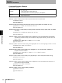
Connection of Reader and each equipment
The reader needs to be connected to antennas and host controller such as PC and PLC to operate as system.
Also when it operates by external Input/Output devices, it needs to be wiring to those device to enable
exchange control signals. This chapter decribes how to connect for those external devices.
Photoelectric sensor
I/O Device
Host Device
Lamp/Buzzer
PC(Personal computer)
PLC
Digital Output
Ethernet or RS-232C
SECTION 4
Digital Input
The Host Device is connected.
The AC Adaptor is connec
Pulg(Accessory)
Connection of Reader and each equipment
The Signal wire of external
input-output devise is connected.
Antenna(Option)
V750 Reader/Writer
AC Adaptor(Accessory)
The Antenna or the Antenna Cable
Antenna Cable(Option) 3m
Antenna Cable(Option) 10m
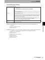
Confirmed item
Please confirm the following items before supplying the AC power supply of the AC adaptor.
No.
Confirmed item
Confirmed content
1
Connection of Antenna
Make sure the connection between antenna cable and antenna, and also
antenna cable and the reader antenna port.
2
Connection with host device
Make sure the connection to the Ethernet or RS-232C port.
3
Connection of Signal wire of external
input-output device
Make sure wiring from the external devices to the terminal at the reader are
securly tighten.
4
Conection of DC Jack of AC adaptor
Make sure the DC jack connected to AC adapter securely.
Pleaese check all accessories are are included when you open the box at first.
50
UHF RFID System
User's Manual
SECTION 4
Diagnosis and Maintenance
Reader/Writer Setting
Ethernet Setting
When you connect the reader via Ethernet I/F, the default setting of the reader are shown as below.
Please check the setting of Ethernet at host system when you connect.
Item
Factory-default
IP Address
192.168.1.200
Subnet Mask
255.255.255.0
Gatewey
192.168.1.254
Communication Port
7090
When you connect the reader via RS-232C I/F, please check the communication setting for both the
host system and the reader.
Setting value
Reader/Writer Setting
Item
Factory-default
Baud Rate
9,600/19,200/38,400/57,600 bps
57,600 bps
Data Length
7/8 bit
7 bit
Parity Bit
Even/Odd/None
Even
Stop Bit
1/2 bit
2 bit
SECTION 4
RS-232C Setting
Initialization of setting
It can return to default setting by sending initialize command(INT).
When you issue the command, refer to "Command Line Interface" in the SECTION 5.
p. 59
UHF RFID System
User's Manual
51
SECTION 4
Diagnosis and Maintenance
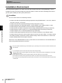
Installation Environment
Since the protection grade for the reader is IP50 and the standard antennas is IP53(IEC60529), it can be
installed only indoor environment within the protection grade. It needs to be refer to following instructions to
get the system reliability and the system performance.
Location
Do not use the Product in the following locations.
• Locations not within the specified operating temperature range (Reader/Writer: -10 to 50°C, Antenna:
-15 to 60°C, RF Tag: -10 to 55°C).
• Locations not within the specified operating humidity range (25% to 85%).
• Locations exposed to any flammable gasses, corrosive gasses, dust, metallic powder, or salts
SECTION 4
• Locations subject to direct vibration or shock outside the specified ranges
• Locations where the reader is exposed to direct sunlight. (Reader/Writer, Normal type Antennas)
• Locations subject to spray of water, oil, or chemicals (Reader/Writer, Normal type Antennas)
Installation Environment
Locations subject to oil, or chemicals (Waterproof type Antennas)
• Locations nearby high-temperature devices such as heater, transformer, high wattage resistor.
• Locations near by power line ( line for deliver large current such as motor cable). If it needs to locate
the reader proximitry to power line, please conduct testing to reduce the influences of electric nois.
• Outdoor (Reader/Writer, Normal type Antennas)
When two or more Reader/Writers are set up, the influence of the interference of the Reader/Writer is
tested enough beforehand and it confirms it.
The communication between RF tag and the reader may vary according to the environment condition. Please test prior
to the operation.
• For the installation, follow the instruction below and conduct enough testing.
• Antenna cables should not gather together with other cables, and only specific antenna cable(Model V740-A01 3M/
10M/20M) can be used.
• Power cables and I/O cables should not gather together with other cables as much as possible.
• If the anntena and antenna cable expose to drops of water, use water-proof tape at the antenna connector.
• Do not remove the metal fittings attached with the water-proof antennas. It may cause the deteroration of performance
of water-proof.
52
UHF RFID System
User's Manual
SECTION 4
Diagnosis and Maintenance
Installation and Wiring
Fix the reader and antennas rigidly by using its mounting hole which mounting schematics shown below.
Use M4 screws with spring washer and flat washer for mounting the reader.
Use M6 screws with spring washer and flat washer for mounting antennas.
Use M3 screws with spring washer and flat washer for mounting RF tag.
Do not use the organic solvent such as screw lock tight after tighten the screws. It may cause the damage to
the mouting panels.
Mounting Hole Dimensions
Reader/Writer(V750-BA50C04-US)
SECTION 4
Installation and Wiring
Spring washer
Flat washer
Mounting Hole Dimensions
235±0.3
152.4±0.3
Four, M4 or Four, 4.5dia.
(Unit : mm)
Tighten the screw with the torque 1.2N•m for moutning.
UHF RFID System
User's Manual
53
SECTION 4
Diagnosis and Maintenance
O
M
R
O
N
Normal type Antennas(V740-HS01CA / V740-HS01LA)
SECTION 4
Spring washer
Flat washer
Installation and Wiring
Mounting Hole Dimension
235±0.2
66±0.2
Eight, M6 or Eight, 6.5 dia.
(Unit : mm)
Tighten the screw with the torque 2N•m for moutning.
54
UHF RFID System
User's Manual
235±0.2
66±0.2
OMRON
SECTION 4
Diagnosis and Maintenance
Wiring for cable
Connection with Host Device
Ethernet Interface
The cable is inserted and connected with the Ethernet port connector of the Reader/Writer.
SECTION 4
• When connecting it directly with PC
Wiring for cable
Crossing Cable
• When connecting it with PC by using the HUB and the Router
Straight Cable
• Use sheiled Ethernet cable.
• For the cable length, use the cables which are available in the market
UHF RFID System
User's Manual
55
SECTION 4
Diagnosis and Maintenance
RS-232C Interface
• Connecting to the PC: Serial setting is set for "flow control: none".
Reader/Writer
D-Sub 9 pin male (inch screw).
RS-232C
PC
D-Sub 9 pin male (inch screw).
Crossing Cable
female
Pin number
1
6
female
Signal name
5
Pin number
Signal name
SECTION 4
1
?
CD
1
2
RD
RD
2
3
SD
SD
3
4
?
ER
4
5
Wiring for cable
SG
SG
5
6
?
DR
6
7
RS
RS
7
8
CS
CS
8
9
?
RI
9
• Connecting to the Omron's PLC (programmable logic controller):
Serial setting is set for "flow control: none".
PLC
Reader/Writer
D-Sub 9 pin male (inch screw).
D-Sub 9 pin female (inch screw).
Special Cable
female
male
5
6
9
Signal name
Pin number
Signal name
1
2
3
4
5
6
7
8
--RD
SD
--SD
RD
RS
CS
1
2
3
4
5
6
7
8
9
---
--SG
--RS
CS
• Cable length should be below 15m.
UHF RFID System
User's Manual
1
Pin number
• Sheiled cable should be grounded at host system side.
56
9
------SG
9
SECTION 4
Diagnosis and Maintenance
Method of assembling Terminal stand plug for external I/O
As an input/output port, the reader contains a terminal block of which connector is removable with
screws.
Terminal block connector: MC 1,5/10-STF-3,81 (produced by PHOENIX CONTACT)
How to wire a terminal block connector with signal cables(s) and how to connect it to the reader body.
1. Wire a signal cable(s) to the terminal block connector. *
9 to 10mm
connector.
Wiring for cable
Tighten the cable fixing screw(s) (clockwise).
SECTION 4
2. Loosen the cable fixing screw(s) (anticlockwise) and insert the signal cable(s) all the way into the
3. Mount the terminal block connector to the reader body.
Fasten the terminal block connector with 2 mounting screws.
*Required Tool: Slotted driver
* Make sure to connect the signal cable to the terminal block connector prior to mounting the connector to the body.
• Check the connection of the cables correctly match each other.
UHF RFID System
User's Manual
57
SECTION 4
Diagnosis and Maintenance
MEMO
SECTION 4
Wiring for cable
58
UHF RFID System
User's Manual
SECTION 5
Command Line Interface
60
Communication Sequence
61
Command/Response Format
66
Communication Command
76
Communication command (Exclusive commands for secure tag)
89
101
Control Command
119
Undefined Command
128
UHF RFID System
User's Manual
Command Line Interface
Setting Command
SECTION 5
Control method
59
SECTION 5
Command Line Interface
Control method
Control by command
The reader writer's operation is directed by transmitting the command from connected host device.
It replies the result of executing the command as a response.
In the operation mode, all operation is controlled by the command according to the content of the
transmitted command. (ex. Read/Write of ID of RF Tag and data, Setting of function of RF Tag, Setting
of communication condition, Setting of Reader/Writer)
Host Device
(ex. Personal computer)
Command
(Instruction)
Operation condition setting
Reader/Writer
Antenna
RF Tag
Response
(Result)
SECTION 5
External input
External output
Communication between
Antenna and RF Tag
Functions and Control
(ex. Processing stop, Output setting)
Control method
Command and Response Flowchart
In the operation mode, the command is transmitted from host device, and it replies from Reader/Writer
the response of the processing result.
There is a state of the following commands and the responses by the difference between the kind of
the command and the communication specification.
1:1 Protocol
When Single once, Setting of communication condition, and Setting of Reader/Writer, etc. are
specified by the command that communicates with the RF tag, one response is transmitted to one
command.
Host Device
Command
Response
Reader/Writer
1:N Protocol
When Single repeat and Multi repeat, etc. are specified by the command that communicates with the
RF tag, two or more responses are transmitted to one command.
Host Device
Reader/Writer
60
UHF RFID System
User's Manual
Command
Response
Response
Response
Response
SECTION 5
Command Line Interface
Communication Sequence
In order to communicate with the RF Tag in the communications area of the Antenna, commands must be
selected and used according to the mode and movement of the RF Tag.
Single Access Mode
In this mode, only a single RF Tag can be in the communications area, otherwise
the result of the first communication with tag replies.
The reader reads a single tag at a time (One-to-one communication). When the reader detects the first
tag, it returns response and terminates transaction (one response/ one transaction). If the reader does
indicates "0" as the number of tags. If the period is not specified, it continues the process until the
termination command has been sent or until it detects a tag.
• A sequence when the reader detects one tag for the specified period.
Just after the reader communicates the tag, it returns a response (reporting the read tag data) to the
host.
Host Device
Command SOC
Timeout
Response
Reader/Writer
Communication Sequence
not detect any tag, it continues the process for a specified period of time. In this case, the response
SECTION 5
Single Once
Read process
RF Tag
RF Tag
• A sequence when the reader does not detect any tag for the specified period
(There is no tag).
At the end of the specified period, the reader returns a response (reporting "no tag") to the host.
Host Device
Command SOC
Timeout
Response
Reader/Writer
Read Process
RF Tag
• A sequence when the reader detects two or more tags for the specified period
Just after the reader communicates first the tag, it returns a response (reporting the read tag data) or
(reporting "no tag") to the host.
Host Device
Command SOC
Timeout
Response
Reader/Writer
Read Process
RF Tag
RF Tag
RF Tag
RF Tag
UHF RFID System
User's Manual
61
SECTION 5
Command Line Interface
Single Repeat
The reader communicates with a single tag at a time (one-to-one communication) and repeats the
communication transaction. When the reader detects the first tag, it returns response to the host, then
it begins the next transaction repeatedly. Whenever it detects an unread tag, it reads the tag and
returns read results to the host. It repeats the transaction until the termination command has been
sent.
• A sequence when the reader detects tags one by one as it repeats the transaction.
Just after the reader communicates a tag, it returns a response (reporting the read tag data) to the
host.
Host Device
Timeout
Command SRP
Response
Reader/Writer
RF Tag
SECTION 5
Communication Sequence
62
Timeout
Timeout
Response
Response
Read Process
Read Process
Read Process
RF Tag
RF Tag
RF Tag
• A sequence when the reader carries out the transaction repeatedly and there is no tag.
At the end of the specified period, the reader returns a response (reporting "no tag") to the host.
Host Device
Timeout
Command SRP
Response
Reader/Writer
Read Process
RF Tag
UHF RFID System
User's Manual
Timeout
Response
Read Process
SECTION 5
Command Line Interface
Multi Access Mode
In this mode, communications with all RF Tags in the communications area can be made on receipt of
the command.
Multi Once
The reader reads multiple tags for a specified period. At the end of the specified period, it returns read
results and finishes the transaction. If the reader does not detect any tag during the specified period, it
SECTION 5
returns a response meaning there is no tag.
• A sequence when the reader detects tags for the specified period.
host.
㪚㫆㫄㫄㪸㫅㪻㩷㪤㪦㪚
㪟㫆㫊㫋㩷㪛㪼㫍㫀㪺㪼
㪫㫀㫄㪼㫆㫌㫋
㪩㪼㫊㫇㫆㫅㫊㪼
Reader/Writer
㪩㪼㪸㪻㩷㪧㫉㫆㪺㪼㫊㫊
㪩㪝㩷㪫㪸㪾
RF Tag
㪩㪝㩷㪫㪸㪾
㪩㪝㩷㪫㪸㪾
㪩㪝㩷㪫㪸㪾
㪩㪝㩷㪫㪸㪾
• A sequence when the reader carries out the transaction and there is no tag.
Communication Sequence
At the end of the specified period , the reader returns a response (reporting the read tags' data) to the
At the end of the specified period, the reader returns a response (reporting "no tag") to the host.
Command MOC
Host Device
Timeout
Restpnse
Reader/Writer
Read Process
RF Tag
• A sequence when the reader detects tags for the specified period. (When it is
not possible to communicate with all tag. )
• At the end of the specified period , the reader returns a response (reporting the read tags' data) to the
host. There is a possibility where tag that was not able to communicate exists, too.
Host Device
Command MOC
Timeout
Response
Reader/Writer
Read Process
RF Tag
RF Tag
RF Tag
RF Tag
RF Tag
RF Tag
RF Tag
RF Tag
RF Tag
RF Tag
RF Tag that was not able to
communicate
UHF RFID System
User's Manual
63
SECTION 5
Command Line Interface
• A sequence when two or more reader detects tags for the specified period.
When it specified multiple antennas for communication with RF tags, the reader is priortized the
communication with RF tags in the field within the timeout period. If the number of RF tags in the field
is enough small, the reader can switch all antennas within the timeout period. If the number of RF tags
in the field is large and the reader can not finish the communcation with all these RF tags during
switching all antennas, the reader responds the RF tags read data at the time of time out even if it do
not switch the all antennas.
Host Device
Command MOC
Timeout
Response
Reader/Writer
Read Process
Antenna 1
Antenna 2
RF Tag
RF Tag
RF Tag
RF Tag
RF Tag
RF Tag
RF Tag
RF Tag
RF Tag
Communication area of Antenna 3
SECTION 5
Communication Sequence
64
UHF RFID System
User's Manual
SECTION 5
Command Line Interface
Multi Repeat
The reader reads multiple tags for a specified period. At the end of the specified period, it returns read
results to the host and then it begins the next transaction until termination command has been sent. At
each period, the reader returns all read tag's results to the host. If it does not read any tag during each
time period, it returns response meaning there is no tag.
• A sequence when the reader detects tags repeatedly.
At the end of the specified period, the reader returns a response (reporting the read tags' data) to the
host.
Host Device
Timeout
Command MRP
Timeout
Response
Reader/Writer
RF Tag
Timeout
Response
Response
Read Process
Read Process
Read Process
Two or more RF Tag
Two or more RF Tag
Two or more RF Tag
At the end of the specified period, the reader returns a response (reporting "no tag") to the host.
Host Device
Timeout
Command MRP
Timeout
Read Process
Response
Read Process
Response
Read Process
RF Tag
UHF RFID System
User's Manual
Communication Sequence
Response
Reader/Writer
Timeout
SECTION 5
• A sequence when the reader carries out the transaction repeatedly and there is no tag.
65
SECTION 5
Command Line Interface
Command/Response Format
Ethernet and RS-232C has almost the same command structure for command line I/F. Command frame has a
Command Code area to control the R/W and Command Data area that is used with Command Code.
Terminator that indicates the end of the frame is [LF].
RS-232C requires a start code [SOH], check data, and [CR] additionally. The start code shall be at the
beginning of the frame, and the check data and the [CR] shall be just forward terminator [LF].
Composition of command frame
Command frame for RS-232C(The shaded portion is only RS-232C. )
SOH
Command Code
Command Data
FCS
CR
LF
1
4
n
2
1
1
FCS Calculation Range
SECTION 5
Command/Response Format
66
SOH (Start Code)
: Indicates the beginning of the frame with SOH (For only RS-232C).
Command Code
: Specifies the command the reader executes.
Command Data
: Specifies the data for use with Command Code
FCS
: Stands for Frame Check Sequence (hereinafter referred to as "FCS". The code is to detect an
FCS error.)The result of the horizontal parity calculation from after SOH through just before the
FCS is expressed by two characters of ASCII code (For only RS-232C).
CR, LF
: Terminator CR(0Dh), LF(0Ah). It is only LF(0Ah) when the command line is Ethernet.
The command frame length from the head to LF(0Ah) is 512 bytes or less.
Command frame for Ethernet
Command Code
Command Data
LF
4
n
1
UHF RFID System
User's Manual
SECTION 5
Command Line Interface
Command Format
Command Code SP Parameter 1 SP
4
1
䊶䊶䊶
n
Item
Command Code
SP Parameter n SP
1
n
SP
n
1
-
Option item
SP
Option value
1
3
1
n
Digit
number
4
1
Option 1
䊶䊶䊶
SP Option n
1
n
Explanation
Consists of four characters in ACSII format.
Refer to Command Code List for information on command codes.
p. 69
n
Mandatory for each command. If there are multiple parameters in a single
command, they must be separated with some spaces and specified in the
specified order. Applicable parameter for each command is shown in the table
in 3.1.5.1.
- (Hyphen) (2Dh)
1
The code in which the option is shown is set.
Option item
3
The option code is specified by three characters.
n
Optional for each command. If there are multiple options in a single command,
they must be separated with some spaces. If it is not specified, default value will
be employed. If multiple option items are specified, they shall be described
continuously. Any order is acceptable.
Parameter
Option
Optional value
* Commands are acceptable regardless of whether upper or lower case letters are used. Any
command works regardless the size combination of characters such as upper case letters, lower
case letters, or mixed one.
UHF RFID System
User's Manual
Command/Response Format
Between the elements (Parameters and Options), " " (space) has to be entered
for one or more character. Even if a two or more characters of " " (space) are
put in, they work same way as one-character " " (space).
SECTION 5
1
SP(Space)(20h)
67
SECTION 5
Command Line Interface
Composition of response frame
Response frame for RS-232C(The shaded portion is only RS-232C. )
㪪㪦㪟
㪚㫆㫄㫄㪸㫅㪻㩷㪚㫆㪻㪼
㪩㪼㫊㫇㫆㫅㫊㪼㩷㪚㫆㪻㪼
㪩㪼㫊㫇㫆㫅㫊㪼㩷㪛㪸㫋㪸
㪝㪚㪪
㪚㪩
㪣㪝
㪈
㪋
㪋
㫅
㪉
㪈
㪈
FCS Calculation Range
SOH (Start Code)
: Indicates the beginning of the frame with SOH (For only RS-232C).
Command Code
: Specifies the command the reader executes.
Response Code
: Indicates the result code of command execution.
Command Data
: Indicates the result data of command execution.
FCS
: Stands for Frame Check Sequence (hereinafter referred to as "FCS". The code is to detect an
FCS error.)The result of the horizontal parity calculation from after SOH through just before the
FCS is expressed by two characters of ASCII code (For only RS-232C).
CR, LF
: Terminator CR(0Dh), LF(0Ah). It is only LF(0Ah) when the command line is Ethernet.
SECTION 5
Response Format
Command Code Response Code SP
Command/Response Format
4
4
Item
Number of
SP ID or Data value 1 SP
RF Tag
1
3
Digit
number
1
n
䊶䊶䊶
1
SP ID or Data value n
1
n
Explanation
Command Code
4
Set same characters specified as a command sent from the host.
Response Code
4
Indicates four-digit hexadecimal numbers by ASCII format.
SP(Space)(20h)
1
Between the elements (Parameters and Options), " " (space) has to be entered
for one or more character. Even if a two or more characters of " " (space) are
put in, they work same way as one-character " " (space).
Option
1
The code in which the option is shown is set.
Number of RF Tag
3
Number of RF Tags for communication commands.
n
The RF tag ID(s) (or data) read by the reader with Hex code. If the reader reads
multiple tags' IDs (or data), it indicates them in line with space(s) between each
ID (or data). Data in hexadecimal numbers does not have [0x].
ID or Data value
* All hexadecimal numbers as commands and data in the read tags are indicated with upper case letters (A to F).
68
UHF RFID System
User's Manual
SECTION 5
Command Line Interface
Command Code List
Comman
d Code
Command Name
Executabl
e in
communic
ation
Description
(1) Communication Command (to communicate with tags)
RDID
Read ID
Reads ID data from the tag memory.
No
WTID
Write ID
Writes ID data into the tag memory.
No
RDDT
Read Data
Reads data from the tag memory (including passwords).
No
WTDT
Write Data
Writes data to the tag memory (including passwords).
No
LOCK
Lock
Sets Lock function in the tag.
No
KILL
Kill
Disables the tag permanently.
No
(2) Setting Command (to set a condition).
Set Reader
Sets the function settings in the reader.
No
Get Reader
Reads the function settings from reader.
Yes
SETO
Set Communication
Sets the communication settings in the reader (temporary setting).
No
GETO
Get Communication
Reads the communication settings from the reader.
Yes
SETC
Set Reader Operation
Sets the operation settings in the reader.
No
GETC
Get Reader Operation
Reads the operation settings from reader.
No
SAVE
Save communication
settings
Save the communication condition into the nonvolatile memories in the
reader (permanent setting).
No
INIT
Initialize
Initializes all settings in the reader.
No
STOP
Stop
Stops the communication with the RF Tags.
Yes
EXIO
External Input Output
control
Eeads input/output port status.
Set condition of output port.
Yes
REST
Reset
Restarts the reader.
Yes
GBYE
Good Bye
Disconnects the Ethernet connection.
No
RRES
Request Resend
Requests to resend the last response data.
Yes
TEST
Test System
Tests the communication between host and the reader.
Reads the operation status from reader.
Yes
NOIS
Noise monitoring
Monitors noise level of the specified antenna.
No
Command/Response Format
(3) Control command (to control the action)
SECTION 5
SETR
GETR
(4) Undefined command (in the response frame only)
ICMD
Illegal Command
Vommand code to be used in the response frame if the R/W receives
undefined command.
-
UHF RFID System
User's Manual
69
SECTION 5
Command Line Interface
Exclusive commands for secure tag
Following decribed Secure RFID protocol command ( Secure function command).
Secure function command can be used the reader which certification number has 001AHB1004 or
001PVAB1002.
The reader which certification number is 001AHB001 can not use this function.
This command is only valid for Secure function command. The EPC global Class1 Generation2 RF tag
which does not support secure function does not respond to this command.
Command
Code
Command Name
Description
Executabl
e in
communic
ation
(1) Communication command (Exclusive commands for secure tag)
SECTION 5
Command/Response Format
70
LKRD
LocK ReaD
(ReadLock)
Forbids reading data by bank unit (UII, TID, USER).
WTMW
WriTe Multiple Words
(WriteMultipleWords)
Writes data into a maximum 8-word area at a time.
LKBK
LocK BlocK
(BlockLock)
Locks up the USER area(s) by block unit.
LKRB
LocK Read Block
(BlockReadLock)
Forbids reading data in the USER area(s) by block unit.
RDSI
ReaD System
Information
(GetSystemInfomation)
Reads information of targeted secure tag (including lock information).
SATT
Set ATTenuate
(SetAttenuate)
Changes communication distance between the antenna and the secure
tags.
No
WTPW
WriTe PassWord
Writes the USER password into tags.
No
User's Manual
No
No
No
No
*A word shown in parentheses corresponds to the command name used in Secure Tag (Hibiki) protocol.
UHF RFID System
No
SECTION 5
Command Line Interface
Response Code List
Category
Normal end
Response Code
Main
Sub
00
00
The received command ended normally with no error.
Parity error
A parity error has occurred in one of the characters of the command
frame (For only RS-232C).
Framing error
A framing error has occurred in one of the characters of the command
frame (For only RS-232C).
Overrun erro
An overrun error has occurred in one of the characters of the command
frame (For only RS-232C).
00
FCS error
The command frame has an incorrect FCS (For only RS-232C).
0X
Command code
error
Incorrect command has been received. The response code is ICMD.
Command
parameter erro
Command parameter is incorrect.
Command option
error
Command option is incorrect.
00
11
00
12
00
(See Note1)
Command
error
14
1X
(See Note1)
2X
(See Note1)
Filter error
Specified filter settins is incorrect.
Ex. Caused by incorrect setting of filtering condition.
Frame length error
A command received from the host exceeds the receive buffer (512
Bytes).
00
LBT busy error
Channel none by can LBT use. (The electric wave cannot be sent. )
1X
Communication
error
During the transaction after tag detection, communication error or
process time out has occurred, and consequently the transaction can
not be completed normally.
Specified password does not match to the one of the target tag.
Communication
error
During the transaction after tag detection, communication error or
process time out has occurred, and consequently the transaction can
not be completed normally
.* In the case of ID write/Data write, a part of data in the tag may have
been written.
Verification error
The reader has not written the data to the tag by reason of verification
error.
Address
specification error
Specifying Bank/Address in the tag memory is incorrect and command
can not be executed.
Data write error
During the data write into the detected tag, sufficient power is not
supplied to the tag.
Antenna derection
error
At the R/W starts up, an appropriate antenna has not been connected to
the specified antenna port.
Antenna error
Error occurred with the antenna connected to the specified antenna port
(even though the antenna is detected normally when start up).
Lock error
When data write or read command is sent for the locked area. It
depends on the tag's chip specifications. (For Monza chip, when these
commands are sent for Lock Bit of User Memory because this area does
not exist.)(See Note2)
Tag error
The tag has been rejected the command process.
15
0X
(See Note1)
00
(See Note1)
70
2X
(See Note1)
RF Tag
communica
tion error
71
00
7A
00
7B
00
1X
(See Note1)
7C
2X
(See Note1)
7E
7F
System
error
9A
00
0X
Command/Response Format
Specified command can not be executed.
Ex. Caused by executing a communication command when the last
command is being executed.
Ex. Caused by incorrect setting of filtering condition.
SECTION 5
Process error
00
18
Description
Normal end
10
13
Response Name
(See Note1)
XX
(See Note1)
System error
An error that blocks command execution has been detected in the
hardware (such as malfunction of inner circuit or temporary execution
error caused by noise).
Note1: 'x' character in response code means one character in the list of 0 to 9 or A to F.
Note2: Depends on the specification of IC chip equipped in the RF tag. ( It occurs at Monza chip when it specified the lock bit
which does not exist in its memory map.
UHF RFID System
User's Manual
71
SECTION 5
Command Line Interface
Command Specification
Parameters and Options for Communication Commands
A communication command consists of parameter(s) mandated for command execution and option
specified if necessary. Following table shows parameters of each command and available options.
Command Data
Read ID
Options
Parameters (mandatory)
Command Code
RDID
Non
Write ID
WTID
Write Data
Read Data
RDDT
Memory Bank, Data Pointer, Data Length
Write Data
WTDT
Memory Bank, Data Pointer, Write Data
seq
ant
tmo
tif
pwd
ptc
Yes
Yes
Yes
Yes
No
@
Δ
Yes
Yes
Yes
Yes
@
Yes
Yes
Yes
Yes
Yes
@
Δ
Yes
Yes
Yes
Yes
@
Lock
LOCK
Lock Code
Δ
Yes
Yes
Yes
Yes
@
Kill
KILL
Non
Δ
Yes
Yes
Yes
Yes
@
- All options can be omitted. If option(s) is omitted, the default value is applied depending on the option
item.
- Kill command requires the option item "-pwd" (if the "-pwd" is not used in command, 7Fxx error will
occur.)
SECTION 5
Parameter Details
To set parameters, items in the following list shall be chosen and be described in to the command one's
Command/Response Format
way down the list.
Parameter
Setting value
Memory Bank
Memory bank of a GEN2 tag for "Read Data" or "Write Data" shall be specified with the following number
in decimal format.
- 0: Reserved Area
- 1: EPC Area
- 2: TID Area
- 3: User Area
Data Pointer
Memory address in the memory bank of the GEN2 tag for "Read Data" or "Write Data" shall be specified
with number(s) in the following range in decimal format.
- Min: 0
- Max: 255
Data Length
Memory size to be accessed for "Read Data" shall be specified with the word number(s) in the following
range in decimal format.
- Min: 1
- Max: 32
-Note: One word length is 16bits.
Write Data
To write data into a tag with "Write ID" or "Write Data" command, the data shall be specified in 32-bit
hexadecimal format as below. (0x not required)
- Format: XXXXXXXX ... XXXXXXXX
X: 0 to 9 , A to F
Ex. 12345678
Lock Code
When Lock command is executed, this code shall be specified depending on the type of lock.
For GEN2, 10-digit Lock value shall be specified with 0, 1 or * (0 and 1 mean Action and * means MASK)
for following five areas; Kill pwd, Access pwd, EPC memory, TID memory, and User memory.
•Format: XXXXXXXXXX
X: 0 , 1 or * (0:Off , 1:On , *:Don't care)
chr.
1
2
Kill pwd
Action
Fields
72
UHF RFID System
User's Manual
pwd
read/
write
perma
lock
3
4
Access pwd
pwd
read/
write
perma
lock
5
6
EPC memory
pwd
write
perma
lock
7
8
TID memory
pwd
write
perma
lock
9
10
User memory
pwd
write
perma
lock
SECTION 5
Command Line Interface
Option Details
Option shall be specified with values following the code that indicates option type.
Code
Item
Default
Value
Specified Value
Communication Specifies the communication sequence according to the operating conditions. For only
sequence
"Read ID" command, all parameters can be specified. For other commands, only SOC
can be specified.
- SOC: Single Once
- SRP: Single Repeat
- MOC: Multi Once
- MRP: Multi Repeat
-seq
SOC
-ant
Antenna ID
Can specify the order of antenna to operate from 1st to 9th with figure of 1, 2, 3 and 4.
The figure 1 to 4 means antenna's identical number. If an antenna is specified multiply,
the antenna executes sequence multiply depend on the order.
- Format: X ... XXXXXXXXX (Max 9 characters)
X: 1 to 4
-ant 1
-tmo
Timeout
Specifies time parameter for communication process in millisecond. The numbers after
rounding down to the 10 is added milliseconds as a specified value (the least significant
digit is always "0"). If the communication sequence is SOC, the specified value is the
communication time. If the value is specified 0 (zero), communication process will
continue until STOP command is executed. If the communication sequence is SRP/MOC/
MRP, the specified value is maximum time between response (0 can't be specified on
SRP/MOC/MRP sequence). (When you determine the value of Timeout, see the section
5.2 "Communication Time".)
- Min:0ms
- Max:2550ms(in DRM off or in firmware version 100-100-100-0)
10000ms(in DRM on and in firmware version 101-101-102-0 or later)
- Step:10ms
-tmo
250
-tif
Tag Information Specifies one or more items as additional information of tag communication results that
are output in the response. Specified item(s) shall be returned according to the specified
order with commas.
- ANT: An antenna number which reads the tag first.
- CNT: The count of tag read.
- EPC: EPC code only.
- PEP: PC bits and EPC code
- PER: PC bits, EPC code, and CRC
- LVL : Receiving level of signals sent from the tags*1
For ID read, EPC/PRP/PER determines the EPC data type to be returned. For ID write or
Data write, if EPC/PEP/PER is specified, EPC data before rewriting shall be returned. (If
EPC data length is 0, it will be "*".)
-tif
EPC
-pwd
Password
Specifies the password data with 32-bit, 8 digit numbers in hexadecimal format for access
of ID Write command, Data Read command, Data Write command, and Lock command,
and Kill password for Kill command. (0x not required)
- XXXXXXXX
For ID Write, Data Write, or Lock, if this option is omitted or specified "00000000", Access
password shall not be used .(If Access password of the Tag is 0x00000000, the tag can
be processed. For Kill command, the Access password shall not be 0x00000000. If so,
7Fxx error occurs.)
-ptc
Tag Protocol
Specifies the number(s) that indicates the protocol type. Multiple numbers can be
specified.
- 1: Class1 Generation2
SECTION 5
-seq
Command/Response Format
-pwd
00000000
-ptc
1
UHF RFID System
User's Manual
73
SECTION 5
Command Line Interface
If you do not specified options, the following condition will apply to each option as default setting.
Option
Default
-seq
SOC
-ant
1
-tmo
250 (ms)
-tif
No additional tag information
-pwd
Access password is not used
-ptc
1 (C1G2)
Notes: Timeout settings.
Please choose the timout value when you use repeat command (SRP/MRP).
It may cause the reader system halt error depending on the Ehternet or RS-232C communiction status due to lots of
packets exchange. If Ethernet network which the reader connected is large, or communnication settings of RS-232C is
low, it requires longer timeout value to avoid this error.
Required parameters and selectable options for each command for the
Secure Tags.
Following table shows parameters to be set and selectable options for communication command
SECTION 5
operation.
Secure function is supported by certificication number at 001AHB1004, 001PVAB1002. The reader
which certification number is 001AHB1001 can not use this function. Also Secure function can only use
Command/Response Format
for the RF tags which supports secure RFID protocol. The standard EPC global Class1 Generation 2
RF tags does not work.
Command Data
Parameters (mandatory)
Command Code
Options
seq
ant
tmo
tif
pwd
ptc
Δ
Yes
Yes
Yes
Yes
@
WTMW Memory bank, data pointer, and data to be written
Δ
Yes
Yes
Yes
Yes
@
Lock Block
LKBK
Block number, user password, and lock code
Δ
Yes
Yes
Yes
Yes
@
Lock Read Block
LKRB
Block number, user password, and lock code
Δ
Yes
Yes
Yes
Yes
@
Lock Read
LKRD
Write Multiple Words
Lock code
Read System Information RDSI
Non
Δ
Yes
Yes
Yes
No
@
Set Attenuate
SATT
Level and lock information
Δ
Yes
Yes
Yes
Yes
@
Write Pass Word
WTPW
Block number and user password
Δ
Yes
Yes
Yes
No
@
*Δ: Only SOC can be specified. @: Only "1" (= Gen2) can be specified.
If you do not specified options, the following condition will apply to each option as default setting.
Option
74
Default
-seq
SOC
-ant
1
-tmo
250 (ms)
-tif
No additional tag information
-pwd
Access password is not used
-ptc
1 (C1G2)
UHF RFID System
User's Manual
SECTION 5
Command Line Interface
Example FCS calculation for RS-232C
FCS is the result of the horizontal parity calculation (Exclusive OR) of the data right after SOH to the
end of the Command data.
RFID -seq MOC -ant 1 -tmo 500
Command
Command code
Command data
SOH
R
D
I
D
_
-
s
e
q
_
M
O
C
_
-
a
n
t
_
1
_
-
t
m
o
_
5
0
0
01
52
44
49
44
20
2D
73
65
71
20
4D
4F
43
20
2D
61
6E
74
20
31
20
2D
74
6D
6F
20
35
30
30
FCS
31
ASCII Code(Hex)
Binary
R
52
0101
0010
D
44
0100
0100
I
49
0100
1001
D
44
0100
0100
(Space)
20
0010
0000
1101
2D
0010
73
0111
0011
e
65
0110
0101
0001
q
71
0111
(Space)
20
0010
0000
M
4D
0100
1101
O
4F
0100
1111
C
43
0100
0011
(Space)
20
0010
0000
-
2D
0010
1101
a
61
0110
0001
n
6E
0110
1110
0100
t
74
0111
(Space)
20
0010
0000
1
31
0011
0001
(Space)
20
0010
0000
-
2D
0010
1101
t
74
0111
0100
m
6D
0110
1101
o
6F
0110
1111
(Space)
20
0010
0000
5
35
0011
0101
0
30
0011
0000
0
30
0011
0000
XOR
19
0001
1001
LF
0D
0A
"19" is translated to "31" and
"39" as ASCII code.
Command/Response Format
s
CR
SECTION 5
Character
39
Note : Programming for communication control
This FCS represents the calculation result of horizontal parity with data and terminater strings. Therefore, The FCS
includes all the code from 00h to FFh.( 00h to 7Fh, in case of data length is 7bits).
Program the communication control to consider that FCS may contain the control charactor such as SOH or CR.
* Depending on the programming tool or coding method, some of character code can not be used. Please check the
programming tool before progrmmaing.
UHF RFID System
User's Manual
75
SECTION 5
Command Line Interface
Communication Command
Read ID (RDID)
Command Format
Command code
R
D
I
SP
Option 1
SP
1
n
1
----
SP
Option n
1
n
D
4
Option code
Description
Available Optional Value
SOC: Single Once
SRP: Single Repeat
Communication sequence
MOC: Multi Once
MRP: Multi Repeat
-seq
-ant
Number of antenna
Specifies order of antenna operation with figure 1-4; max 9 characters.
-tmo
Process time out(msec)
0, or from 100 to 5,000 in 10msec increments
SECTION 5
-tif
Communication Command
Additional information responded with data
ANT: antenna number
CNT: count of read tags
EPC: EPC code
PEP: PC bits and EPC code
PER: PC bits, EPC code and CRC
LVL: Receiving level of signals sent from the tags
Refer to the Option Details in detail.
Additional tag information
p. 73
-ptc
Tag protocol
1
Response Format
Command code
R
D
I
Response code
SP
Tag count
SP
ID and
TIF information
SP
4
1
3
1
n
1
----
SP
ID and
TIF information
1
n
D
4
Item
Response code
Description
0000: Normal end
For other Response codes, refer to Response Code List.
p. 71
76
Tag count
Count of read tag(s)
ID and TIF information
ID read from tag and Tif information specified with command.
Each optional value for tif information lines with comma separation.
UHF RFID System
User's Manual
SECTION 5
Command Line Interface
Command/Response Example
Read ID (RDID)
Command
RDID(S)[options...]<LF>
(S): Space code
[options...]: When it is necessary, the option is specified.
Response
RDID[RC](S)[CNT](S)[ID1 with ITM1](S)...[IDn with ITMn]<LF>
(S): Space code
[RC]: Response Code
[CNT]: Tag Count
[IDn with ITMn]: tagID with Items indicated by TIF option. Items are delimited by a comma.
Note: If EPC data length is "0" (zero), the ID shall be "*".
Example 1) When command is processed with all options omitted and the R/W reads a single tag
(Each option item is specified with default values):
[Tx] RDID<LF>
[Rx] RDID0000 001 1234567890ABCDEF12345678<LF>
* Without any options, the command is executed with [-seq SOC -ant 1 -tmo 250] and EPC
data [1234567890ABCDEF12345678] is returned.
R/W reads two tags:
[Tx] RDID -seq MOC -ant 12<LF>
Example 3) When [MultiRepeat, Antenna 1-4, read items; PC+EPC+CRC, Antenna, Read count] is
specified, the command is executed, and when the reader reads a single tag:
[Tx] RDID -seq MRP -ant 1234 -tif PER,ANT,CNT<LF>
[Rx] RDID0000 001 3000111111111111111111111111ABCD,2,3 <LF>
* The code is returned with comma-separation. EPC code including PC code; 3000 and
CRC; ABCD, antenna ID; 2, and read count; 3 are returned.
Communication Command
[Rx] RDID0000 002 111111111111111111111111 222222222222222222222222<LF>
SECTION 5
Example 2) When [SingleOnce, Antenna 1 and 2] is specified, the command is executed, and when the
Example 4) When [MultiRepeat, Antenna; 1-4 (Antenna 1 is used as main antenna), Timeout; 1000ms]
is specified, the command is executed and then the reader read 10 tags:
[Tx] RDID -seq MRP -ant12131411 -tmo 1000<LF>
[Rx] RDID0000 010 111111111111111111111111 222222222222222222222222
...(7 Tag IDs)... AAAAAAAAAAAAAAAAAAAAAAAA<LF>
Example 5) When [MultiOnce, Antenna 1, read items; EPC+LVL] is specified, the command is
executed, and when the reader reads two tags.
[Tx] RDID -seq MOC -ant 1 -tif EPC,LVL<LF>
[Rx] RDID0000 002 111111111111111111111111,-55.25 222222222222222222222222 48.125<LF>
Example 6) When an error occurred during communication process:
[Tx] RDID -seq SOC -ant 4<LF>
[Rx] RDID7011<LF>
* The error code [Code:7011] is returned.
UHF RFID System
User's Manual
77
SECTION 5
Command Line Interface
Write ID (WTID)
Command Format
Command code
W
T
I
SP
Written data
SP
Option 1
SP
1
12byte
(24 characters)
1
n
1
----
SP
Option n
1
n
D
4
Item
Description
Written data
Specifies hexadecimal number in word (32 bits) increments.
Option code
Description
Available Optional Value
-seq
Communication sequence SOC: Single Once
-ant
Number of antenna
Specifies order of antenna operation with figure 1-4; max 9 characters.
-tmo
Process time out(msec)
0, or from 100 to 5,000 in 10msec increments
SECTION 5
-tif
Additional information responded with data
ANT: antenna number
CNT: count of read tags
EPC: EPC code
PEP: PC bits and EPC code
PER: PC bits, EPC code and CRC
Refer to the Option Details in detail.
Additional tag information
Communication Command
p. 73
-pwd
Access password
Specifies a password with 8-digit hex number (32-bit word). It is essential unless the
value in the area of tag Access Password is zero. It is active only when the area
specified by tag is locked for read and write.
-ptc
Tag protocol
1
Response Format
Command code
W
T
I
Response code
SP
Tag count
SP
TIF information
SP
4
1
3
1
n
1
----
SP
TIF information
1
n
D
4
Item
Response code
Description
0000: Normal end
For other Response codes, refer to Response Code List.
p. 71
78
Tag count
Count of written tag(s)
TIF information
Tif information specified with command.
Each optional value for tif information lines with comma separation.
UHF RFID System
User's Manual
SECTION 5
Command Line Interface
Command/Response Example
Write ID (WTID)
Command
WTID(S)WriteData(S)[Options...]<LF>
(S): Space code
[options...]: When it is necessary, the option is specified.
WriteData: Data to be written in 4-digit hexadecimal number (Max: 128 characters).
Response
WTID[RC](S)[CNT](S)[ITM 1](S)...[ITEM n]<LF>
(S): Space code
[RC]: Response Code
[CNT]: Tag Count
[ITM n]: Items indicated by TIF option. Items are delimited by a comma.
Note: If EPC/PEP/PER are specified for TIF, EPC data shall be the data before rewrite. If data
length is zero during EPC specification, data shall become "*".
Example 1) When all option values are default values and ID 1234567890ABCDEF12345678 is
specified, the command is executed and write process has been completed successfully:
[Tx] WTID 1234567890ABCDEF12345678<LF>
[Rx] WTID0000 001<LF>
tag information, the command is executed and then the reader has succeeded.
[Rx] WTID0000 001 444444444444444444444444<LF>
* If -tif is specified for EPC code, tag's EPC data before rewritten is returned. If the tag had
an EPC data "444444444444444444444444" as last ID, response is as above.
Example 3) When 1234567890ABCDEF12345678 and antenna are specified for write data and tag
information, the command is executed and then the reader has succeeded to write data
with antenna 1.
[Tx] WTID 1234567890ABCDEF12345678 -tif EPC,ANT<LF>
Communication Command
[Tx] WTID 555555555555555555555555 -tif EPC <LF>
SECTION 5
Example 2) When ID "555555555555555555555555" and EPC code are specified for write data and
[Rx] WTID0000 001 *,1<LF>
* If the tag had no EPC data before, [*] is returned.
Example 4) When FFFFFFFFFFFFFFFFFFFFFFFF, 2, and 300 are specified for ID, antenna, timeout
and the command is executed but no tag is found:
[Tx] WTID FFFFFFFFFFFFFFFFFFFFFFFF -ant 2 -tmo 300<LF>
[Rx] WTID0000 000<LF>
Example 5) When 123412341234123412341234 and ABCDABCD are specified for ID and access
password is executed but access password is not matched:
[Tx] WTID 123412341234123412341234 -pwd ABCDABCD<LF>
[Rx] WTID0000 000<LF>
Example 6) When an error has occurred during communication process:
[Tx] WTID 1234567890ABCDEF12345678<LF>
[Rx] WTID7012<LF>
* The error code [Code:7012] is returned.
UHF RFID System
User's Manual
79
SECTION 5
Command Line Interface
Read Data (RDDT)
Command Format
Command code
R
D
D
SP
Memory Bank
SP
Data Pointer
SP
Data Length
SP
Option 1
SP
1
1
1
1 to 3
1
1 or 2
1
n
1
----
SP
Option n
1
n
T
4
Parameter
Description
Memory bank
Specifies memory bank of Gen2 tag.
0: Reserved Area
1: EPC Area
2: TID Area
3: User Area
Data pointer
Specifies memory address intended to access in the memory bank.
0-255
Data Length
Specifies hexadecimal number in word (16 bits) increments.
1-32
Option code
Description
Available Optional Value
SECTION 5
Communication Command
-seq
SOC: Single Once
SRP: Single Repeat
Communication sequence
MOC: Multi Once
MRP: Multi Repeat
-ant
Number of antenna
Specifies order of antenna operation with figure 1-4; max 9 characters.
-tmo
Process time out(msec)
0, or from 100 to 5,000 in 10msec increments
-tif
Additional information responded with data
ANT: antenna number
CNT: count of read tags
EPC: EPC code
PEP: PC bits and EPC code
PER: PC bits, EPC code and CRC
Refer to the Option Details in detail.
Additional tag information
p. 73
-pwd
Access password
Specifies a password with 8-digit hex number (32-bit word). It is essential unless the
value in the area of tag Access Password is zero. It is active only when the area
specified by tag is locked for read and write.
-ptc
Tag protocol
1
Response Format
Command code
R
D
D
Response code
SP
Tag count
SP
Data and
TIF information
SP
4
1
3
1
n
1
----
SP
Data and
TIF information
1
n
T
4
Item
Response code
Description
0000: Normal end
For other Response codes, refer to Response Code List.
p. 71
80
Tag count
Count of read tag(s)
Data and TIF information
Data read from tag and Tif information specified with command.
Each optional value for tif information lines with comma separation.
UHF RFID System
User's Manual
SECTION 5
Command Line Interface
Command/Response Example
Read Data (RDDT)
Command
RDDT(S)mbk(S)dpt(S)dln(S)[options...]<LF>
(S): Space code
mbk: Memory Bank
dpt: Data Pointer
dln: Data Length
[options...]: When it is necessary, the option is specified.
Response
RDDT[RC](S)[CNT](S)[Data 1 with ITM 1](S)...[Data n with ITM n](<LF>
(S): Space code
[RC]: Response Code
[CNT]: Tag Count
[Data n with ITM n]: Data with Items indicated by TIF option. Items are delimited by a comma.
Example 1) When [Memory bank; 0, Start address(=Data pointer); 0, word count to be read(=Data
length); 1] is specified, other settings are default value and then read process has
completed successfully:
[Tx] RDDT 0 0 1<LF>
[Rx] RDDT0000 001 1234<LF>
length); 8] is specified, other settings are default value and then read process has
[Rx] RDDT0000 001 BCAD300055555555<LF>
* If -tif is specified for EPC code, tag's EPC data before rewritten is returned. If the tag had
an EPC data "444444444444444444444444" as last ID, response is as above.
Example 3) ) When [Memory bank; 1, Start address(=Data pointer); 2, word count to be read(=Data
length); 3, Antenna; 1 to 3, Tag information; EPC and antenna id] is specified and read
process has succeeded:
Communication Command
completed successfully:
[Tx] RDDT 1 0 4<LF>
SECTION 5
Example 2) When [Memory bank; 1, Start address(=Data pointer); 0, word count to be read(=Data
[Tx] RDDT 1 2 3 -ant 123 -tif EPC,ANT<LF>
[Rx] RDDT0000 001 111122223333,1234567890ABCDEF12345678,2<LF>
* In this case, the read data is [111122223333], the tag EPC code is
[1234567890ABCDEF12345678], and the read antenna ID is [2].
Example 4) When indicated address can not supported:
[Tx] RDDT 0 0 8<LF>
[Rx] RDDT0000 000<LF>
* No count data is returned.
Example 5) When an incorrect address[1000] is specified:
[Tx] RDDT 0 1000 1 -ant 123<LF>
[Rx] RDDT1412<LF>
* The command data error [Code:1412] is returned.
Example 6) When an error has occurred during communication process:
[Tx] RDDT 0 0 1 -ant 123<LF>
[Rx] RDDT7012<LF>
* The error code [Code:7012] is returned.
UHF RFID System
User's Manual
81
SECTION 5
Command Line Interface
Write Data (WTDT)
Command Format
Command code
W
T
D
SP
Memory Bank
SP
Data Pointer
SP
Written data
SP
Option 1
SP
1
1
1
1 to 3
1
n
1
n
1
----
SP
Option n
1
n
T
4
Item
Description
Memory bank
Specifies memory bank of Gen2 tag.
0: Reserved Area
1: EPC Area
2: TID Area
3: User Area
Data pointer
Specifies memory address intended to access in the memory bank.
0-255
Written data
Specifies hexadecimal number in word (16 bits) increments.
1-32
Option code
Description
SECTION 5
-seq
Available Optional Value
Communication sequence SOC: Single Once
-ant
Number of antenna
Specifies order of antenna operation with figure 1-4; max 9 characters.
-tmo
Process time out(msec)
0, or from 100 to 5,000 in 10msec increments
Communication Command
-tif
Additional information responded with data
ANT: antenna number
CNT: count of read tags
EPC: EPC code
PEP: PC bits and EPC code
PER: PC bits, EPC code and CRC
Refer to the Option Details in detail.
Additional tag information
p. 73
-pwd
Access password
Specifies a password with 8-digit hex number (32-bit word). It is essential unless the
value in the area of tag Access Password is zero. It is active only when the area
specified by tag is locked for read and write.
-ptc
Tag protocol
1
Response Format
Command code
W
T
D
Response code
SP
Tag count
SP
TIF information
SP
4
1
3
1
n
1
----
SP
TIF information
1
n
T
4
Item
Response code
Description
0000: Normal end
For other Response codes, refer to Response Code List.
p. 71
82
Tag count
Count of written tag(s)
TIF information
Tif information specified with command.
Each optional value for tif information lines with comma separation.
UHF RFID System
User's Manual
SECTION 5
Command Line Interface
Command/Response Example
Write Data (WTDT)
Command
WTDT(S)mbk(S)dpt(S)WriteData(S)[options...]<LF>
(S): Space code
mbk: Memory Bank
dpt: Data Pointer
WriteData; Data to be written
[options...]: When it is necessary, the option is specified.
Response
WTDT[RC](S)[CNT](S)[ITM 1](S)...[ITM n]<LF>
(S): Space code
[RC]: Response Code
[CNT]: Tag Count
[ITM n]: Items indicated by TIF option. Items are delimited by a comma.
Note: If EPC/PEP/PER are specified for TIF option, EPC data shall be the data before rewrite. If
data length is zero during EPC specification, data shall become "*".
Example 1) When [Memory bank; 0, Start address(=Data pointer); 0, Data; 0x1234 (one word)] is
specified, other setting are default and then the write process has been succeeded:
[Tx] WTDT 0 0 1234<LF>
SECTION 5
[Rx] WTDT0000 001<LF>
Example 2) When [Memory bank;1, Start address(=Data pointer); 3, Data;
antenna id] is specified:
[Tx] WTDT 1 3 1234567890ABCDEF12345678 -ant 23 -tmo 200 -tif ANT<LF>
[Rx] WTDT0000 001 2<LF>
* In this case, the response code has an antenna ID which is used in writing process.
Example 3) When specified address is not supported:
[Tx] WTDT 1 8 12345678<LF>
[Rx] WTDT0000 000<LF>
Communication Command
0x1234567890ABCDEF12345678, Antenna; 2 and 3, Timeout; 200, Tag information;
* No count response is returned.
Example 4) When specified address is locked:
[Tx] WTDT 0 0 AAAAAAAA<LF>
[Rx] WTDT0000 000<LF>
* No count response is returned.
Example 5) When [Memory bank; 1, Start address=(Data pointer); 2, Data; 0xABCDEFGH] is specified
and a format error has occurred:
[Tx] WTDT 1 2 ABCDEFGH<LF>
[Rx] WTDT1412<LF>
* The error code [Code:1412] is returned.
Example 6) When an error occurred during communication process:
[Tx] WTDT 1 32 1234567890ABCDEF12345678 -ant 23<LF>
[Rx] WTDT7011<LF>
* The error code [Code:7011] is returned.
UHF RFID System
User's Manual
83
SECTION 5
Command Line Interface
Lock (LOCK)
Command Format
Command code
L
O
C
SP
Lock Code
SP
Option 1
SP
1
10
1
n
1
----
SP
Option n
1
n
K
4
Item
Description
Specifies a lock type of an (password / memory) area intended to be controlled with double digits
code shown as below.
(1)
(2)
(3)
Kill pwd
pwd
R/W
Lock Code
Access pwd
perma
lock
pwd
R/W
perma
lock
(5)
(6)
EPC memory
pwd
write
perma
lock
(7)
(8)
TID memory
pwd
write
Pwd
(R/W)
(Write)
Perma
lock
0
0
Cancels temporal lock.
0
1
Unlocks permanently.
1
0
Locks temporally. (It can be unlocked.)
1
1
Locks permanently. (It cannot be unlocked.)
*
*
No lock control
SECTION 5
Communication Command
Option code
(4)
perma
lock
(9)
User memory
pwd
write
Description
Available Optional Value
Communication sequence SOC: Single Once
-ant
Number of antenna
Specifies order of antenna operation with figure 1-4; max 9 characters.
-tmo
Process time out(msec)
0, or from 100 to 5,000 in 10msec increments
Additional tag information
perma
lock
Type of lock
-seq
-tif
(10)
Additional information responded with data
ANT: antenna number
CNT: count of read tags
EPC: EPC code
PEP: PC bits and EPC code
PER: PC bits, EPC code and CRC
Refer to the Option Details in detail.
p. 73
84
-pwd
Access password
Specifies a password with 8-digit hex number (32-bit word). It is essential unless the
value in the area of tag Access Password is zero. It is active only when the area
specified by tag is locked for read and write.
-ptc
Tag protocol
1
UHF RFID System
User's Manual
SECTION 5
Command Line Interface
Response Format
Command code
L
O
C
Response code
SP
Tag count
SP
TIF information
SP
4
1
3
1
n
1
----
SP
TIF information
1
n
K
4
Item
Response code
Description
0000: Normal end
For other Response codes, refer to Response Code List.
p. 71
Tag count
Count of locked tag(s)
TIF information
Tif information specified with command.
Each optional value for tif information lines with comma separation.
SECTION 5
Communication Command
UHF RFID System
User's Manual
85
SECTION 5
Command Line Interface
Command/Response Example
Lock (LOCK)
Command
LOCK(S)LockCode(S)[options...]<LF>
(S): Space code
LockCode: Lock Code (10 characters 0/1/*)
[options...]: When it is necessary, the option is specified.
Response
LOCK[RC](S)[CNT](S)[ITM 1](S)...[ITM n]<LF>
(S): Space code
[RC]: Response Code
[CNT]: Tag Count
[ITM n]: Items indicated by TIF option. Items are delimited by a comma.
Example 1) When [EPC memory; locked temporarily] is set:
[Tx] LOCK ****10****<LF>
[Rx] LOCK0000 001<LF>
Example 2) When [Access password and Kill password; locked temporarily] is set with password;
0xABCDABCD:
SECTION 5
[Tx] LOCK 1010****** -pwd ABCDABCD<LF>
[Rx] LOCK0000 001<LF>
Communication Command
Example 3) When [Access password and Kill password; unlocked] is set with [password;
0xAAAAAAAA, tag information; EPC code and antenna:
[Tx] LOCK 0000****** -pwd AAAAAAAA -tif EPC,ANT<LF>
[Rx] LOCK0000 001 777777777777777777777777,1<LF>
Example 4) When [Password; 0xFFFFFFFF, all memories are locked permanently] is set:
[[Tx] LOCK 1111111111 -pwd FFFFFFFF<LF>
[Rx] LOCK0000 001<LF>
* The EPC code of the tag is [1234567890ABCDEF12345678].
Example 5) When [Password; 0x12341234, all memories are locked permanently] is specified and
specified password is incorrect:
[Tx] LOCK 1111111111 -pwd 12341234<LF>
[Rx] LOCK7011<LF>
* The communication error [Code:7011 (in this case)] is returned.
Example 6) When [Password; 0xAAAAAAAA, Lock code;22222222] is specified and specified lock
code is incorrect:
[Tx] LOCK 2222222222 -pwd AAAAAAAA<LF>
[Rx] LOCK1412<LF>
* The error code [Code:1412] is returned.
86
UHF RFID System
User's Manual
SECTION 5
Command Line Interface
Kill (KILL)
Command Format
Command code
K
I
L
SP
Kill password
L
SP
Option 1
SP
1
n
1
----
SP
Option n
1
n
-pwd XXXXXXXX
4
1
13
Item
Description
Specifies a KILL Password.
The password set previously in the Kill password area corresponding.
- pwd XXXXXXXX
Kill password
* When all 0 is specified, the KILL command cannot be used.
The values other than 0 are set to KILL Password area before KILL Command is executed.
Option code
Description
Available Optional Value
Communication sequence SOC: Single Once
-ant
Number of antenna
Specifies order of antenna operation with figure 1-4; max 9 characters.
-tmo
Process time out(msec)
0, or from 100 to 5,000 in 10msec increments
Additional information responded with data
ANT: antenna number
CNT: count of read tags
EPC: EPC code
PEP: PC bits and EPC code
PER: PC bits, EPC code and CRC
Refer to the Option Details in detail.
Additional tag information
Communication Command
-tif
SECTION 5
-seq
p. 73
-ptc
Tag protocol
1
Response Format
Command code
K
I
L
Response code
SP
Tag count
SP
TIF information
SP
4
1
3
1
n
1
----
SP
TIF information
1
n
L
4
Item
Response code
Description
0000: Normal end
For other Response codes, refer to Response Code List.
p. 71
Tag count
Count of killed tag(s)
TIF information
Tif information specified with command.
Each optional value for tif information lines with comma separation.
UHF RFID System
User's Manual
87
SECTION 5
Command Line Interface
Command/Response Example
Kill (KILL)
Command
KILL(S)[options...]<LF>
(S): Space code
[options...]: When it is necessary, the option is specified.
Response
KILL[RC](S)[CNT](S)[ITM n](S)...[ITM n]<LF>
(S): Space code
[RC]: Response Code
[CNT]: Tag Count
[ITMn]: Items indicated by TIF option. Items are delimited by a comma.
Example 1) When [Password; 0x22222222] is specified and then KILL command is completed
normally:
[Tx] KILL -pwd 22222222<LF>
[Rx] KILL0000 001<LF>
Example 2) When [Password; 0xAAAABBBB, Antenna; 3, Tag information; PER and ANT] is specified
SECTION 5
and KILL command has completed normally:
[Tx] KILL -pwd AAAABBBB -ant 3 -tif PER,ANT<LF>
[Rx] KILL0000 001 30001234567890ABCDEF12345678ABCD,3<LF>
* The PC code of the tag is [3000], EPC code is [1234567890ABCDEF12345678], CRC is
Communication Command
[ABCD], and command executed Antenna ID is [3].
Example 3) When [Password; 0x12345678] is specified and password data has been incorrect:
[Tx] KILL -pwd 12345678<LF>
[Rx] KILL7012<LF>
* The error code [Code:7012] is returned.
Example 4) When [Password; 0x12] is specified and password length has been incorrect:
[Tx] KILL -pwd 12<LF>
[Rx] KILL1421<LF>
* The error code [Code:1421] is returned.
88
UHF RFID System
User's Manual
SECTION 5
Command Line Interface
Communication command (Exclusive commands for secure tag)
Lock Read (LKRD)
Command Format
Command code
L
K
R
SP
Lock code
SP
Option 1
SP
1
6
1
n
1
----
SP
Option n
1
n
D
4
Item
Description
Specifies a lock type of an (memory) area intended to be controlled with double digits code shown
as below.
(1)
(2)
(3)
EPC memory
pwd
write
Pwd
read
Perma
lock
0
0
pwd
write
perma
lock
(6)
pwd
write
perma
lock
Type of lock
Cancels temporal lock.
0
1
Unlocks permanently.
1
0
Locks temporally. (It can be unlocked.)
1
1
Locks permanently. (It cannot be unlocked.)
*
*
No lock control
Description
Available Optional Value
-seq
Communication sequence SOC: Single Once
-ant
Number of antenna
Specifies order of antenna operation with figure 1-4; max 9 characters.
The figure 1 to 4 is antenna's identical number.
-tmo
Process time out(msec)
0, or from 10 to 2550 in 10msec increments (in DRM off)
0, or from 10 to 10000 in 10msec increments (in DRM on)
-tif
Additional tag information
Additional information responded with data
ANT: antenna number
CNT: count of read tags
EPC: EPC code
PEP: PC bits and EPC code
PER: PC bits, EPC code and CRC
Refer to the Option Details in detail.
p. 73
-pwd
Access password
Specifies a password with 8-digit hex number (32-bit word). It is essential unless the
value in the area of tag Access Password is zero.
-ptc
Tag protocol
1 (Gen2)
UHF RFID System
User's Manual
Communication command (Exclusive commands for secure tag)
Option code
perma
lock
(5)
User memory
SECTION 5
Lock Code
(4)
TID memory
89
SECTION 5
Command Line Interface
Response Format
Command code
L
K
R
Response code
SP
Tag count
SP
TIF information
4
1
3
1
n
D
4
Item
Response code
Description
0000: Normal end
For other Response codes, refer to Response Code List.
p. 71
Tag count
Count of locked tag(s)
TIF information
Tif information specified with command.
Each optional value for tif information lines with comma separation.
Secure function is supported by certificication number at 001AHB1004, 001PVAB1002. The reader which certification
number is 001AHB1001 can not use this function. Also Secure function can only use for the RF tags which supports
secure RFID protocol. The standard EPC global Class1 Generation 2 RF tags does not work.
SECTION 5
Communication command (Exclusive commands for secure tag)
90
UHF RFID System
User's Manual
SECTION 5
Command Line Interface
Write Multiple Words (WTMW)
Command Format
Command code
W
T
M
SP
Memory Bank
SP
Data Pointer
SP
Written data
SP
Option 1
SP
1
1
1
1 to 3
1
(1 to 3)×4
1
n
1
----
SP
Option n
1
n
W
4
Item
Description
Memory bank
Specifies memory bank of Gen2 tag.
0: Reserved Area
1: EPC Area
2: TID Area
3: User Area
Data pointer
Specifies memory address intended to access in the memory bank. (in word [16 bits] increments)
0-255
Written data
Specifies hexadecimal number in word (16 bits) increments; maximum 32 words
Option code
Description
Available Optional Value
-ant
Number of antenna
Specifies order of antenna operation with figure 1-4; max 9 characters.
The figure 1 to 4 is antenna's identical number.
-tmo
Process time out(msec)
0, or from 10 to 2550 in 10msec increments (in DRM off)
0, or from 10 to 10000 in 10msec increments (in DRM on)
-tif
Additional information responded with data
ANT: antenna number
CNT: count of read tags
EPC: EPC code
PEP: PC bits and EPC code
PER: PC bits, EPC code and CRC
Refer to the Option Details in detail.
Additional tag information
p. 73
-pwd
Access password
Specifies a password with 8-digit hex number (32-bit word).
It is essential unless the value in the area of tag Access Password is zero. It is active
only when the area specified by tag is locked for read and write.
-ptc
Tag protocol
1 (Gen2)
Response Format
Command code
W
T
M
Response code
SP
Tag count
SP
TIF information
4
1
3
1
n
W
4
Item
Response code
Description
0000: Normal end
For other Response codes, refer to Response Code List.
Communication command (Exclusive commands for secure tag)
Communication sequence SOC: Single Once
SECTION 5
-seq
p. 71
Tag count
Count of written tag(s)
TIF information
Tif information specified with command.
Each optional value for tif information lines with comma separation.
Secure function is supported by certificication number at 001AHB1004, 001PVAB1002. The reader which certification
number is 001AHB1001 can not use this function. Also Secure function can only use for the RF tags which supports
secure RFID protocol. The standard EPC global Class1 Generation 2 RF tags does not work.
UHF RFID System
User's Manual
91
SECTION 5
Command Line Interface
Lock Block (LKBK)
Command Format
Command code
L
K
B
SP
K
Block
SP
User password
SP
Lock code
SP
Option 1
SP
1
8
1
4
1
n
1
----
SP
Option n
1
n
number
4
1
1
Item
Description
Block number
Specifies memory address of the targeted area in the user memory.
1-5
User password
Specifies a password for each user area.
The password should be same as the password set previously in the password area corresponding
to the block number set above.
Specifies a lock type of an (password/memory) area intended to be controlled with double digits
code shown as below.
(1)
(2)
(3)
u-pass
SECTION 5
Communication command (Exclusive commands for secure tag)
92
pwd
R/W
Lock Code
Option code
(4)
U-Pass User
perma
lock
pwd
write
perma
lock
Pwd
(R/W)
(Write)
Perma
lock
0
0
Cancels temporal lock.
0
1
Unlocks permanently.
1
0
Locks temporally. (It can be unlocked.)
1
1
Locks permanently. (It cannot be unlocked.)
*
*
No lock control
Type of lock
Description
Available Optional Value
-seq
Communication sequence SOC: Single Once
-ant
Number of antenna
Specifies order of antenna operation with figure 1-4; max 9 characters.
The figure 1 to 4 is antenna's identical number.
-tmo
Process time out(msec)
0, or from 10 to 2550 in 10msec increments (in DRM off)
0, or from 10 to 10000 in 10msec increments (in DRM on)
-tif
Additional tag information
Additional information responded with data
ANT: antenna number
CNT: count of read tags
EPC: EPC code
PEP: PC bits and EPC code
PER: PC bits, EPC code and CRC
Refer to the Option Details in detail.
p. 73
-pwd
Access password
Specifies a password with 8-digit hex number (32-bit word).
It is essential unless the value in the area of tag Access Password is zero.
-ptc
Tag protocol
1 (Gen2)
UHF RFID System
User's Manual
SECTION 5
Command Line Interface
Response Format
Command code
L
K
B
Response code
SP
Tag count
SP
TIF information
4
1
3
1
n
K
4
Item
Response code
Description
0000: Normal end
For other Response codes, refer to Response Code List.
p. 71
Tag count
Count of locked tag(s)
TIF information
Tif information specified with command.
Each optional value for tif information lines with comma separation.
Secure function is supported by certificication number at 001AHB1004, 001PVAB1002. The reader which certification
number is 001AHB1001 can not use this function. Also Secure function can only use for the RF tags which supports
secure RFID protocol. The standard EPC global Class1 Generation 2 RF tags does not work.
SECTION 5
Communication command (Exclusive commands for secure tag)
UHF RFID System
User's Manual
93
SECTION 5
Command Line Interface
Lock Read Block (LKRB)
Command Format
Command code
L
K
R
SP
B
Block
SP
User password
SP
Lock code
SP
Option 1
SP
1
8
1
2
1
n
1
----
SP
Option n
1
n
number
4
1
1
Item
Description
Block number
Specifies memory address of the targeted area in the user memory.
1-5
User password
Specifies a password for each user area.
The password should be same as the password set previously in the password area corresponding
to the block number set above.
Specifies a lock type of an (password/memory) area intended to be controlled with double digits
code shown as below.
(1)
(2)
U-Pass User
SECTION 5
Communication command (Exclusive commands for secure tag)
94
pwd
read
Lock Code
Option code
perma
lock
Pwd
(R/W)
(Write)
Perma
lock
0
0
Cancels temporal lock.
0
1
Unlocks permanently.
1
0
Locks temporally. (It can be unlocked.)
1
1
Locks permanently. (It cannot be unlocked.)
*
*
No lock control
Type of lock
Description
Available Optional Value
-seq
Communication sequence SOC: Single Once
-ant
Number of antenna
Specifies order of antenna operation with figure 1-4; max 9 characters.
The figure 1 to 4 is antenna's identical number.
-tmo
Process time out(msec)
0, or from 10 to 2550 in 10msec increments (in DRM off)
0, or from 10 to 10000 in 10msec increments (in DRM on)
-tif
Additional tag information
Additional information responded with data
ANT: antenna number
CNT: count of read tags
EPC: EPC code
PEP: PC bits and EPC code
PER: PC bits, EPC code and CRC
Refer to the Option Details in detail.
p. 73
-pwd
Access password
Specifies a password with 8-digit hex number (32-bit word).
It is essential unless the value in the area of tag Access Password is zero.
-ptc
Tag protocol
1 (Gen2)
UHF RFID System
User's Manual
SECTION 5
Command Line Interface
Response Format
Command code
L
K
R
Response code
SP
Tag count
SP
TIF information
4
1
3
1
n
W
4
Item
Response code
Description
0000: Normal end
For other Response codes, refer to Response Code List.
p. 71
Tag count
Count of locked tag(s)
TIF information
Tif information specified with command.
Each optional value for tif information lines with comma separation.
Secure function is supported by certificication number at 001AHB1004, 001PVAB1002. The reader which certification
number is 001AHB1001 can not use this function. Also Secure function can only use for the RF tags which supports
secure RFID protocol. The standard EPC global Class1 Generation 2 RF tags does not work.
SECTION 5
Communication command (Exclusive commands for secure tag)
UHF RFID System
User's Manual
95
SECTION 5
Command Line Interface
Read System Information (RDSI)
Command Format
Command code
R
D
S
4
Option code
Option 1
SP
1
n
1
----
SP
Option n
1
n
Description
Available Optional Value
-seq
Communication sequence SOC: Single Once
-ant
Number of antenna
Specifies order of antenna operation with figure 1-4; max 9 characters.
The figure 1 to 4 is antenna's identical number.
-tmo
Process time out (msec)
0, or from 10 to 2550 in 10msec increments (in DRM off)
0, or from 10 to 10000 in 10msec increments (in DRM on)
-tif
SECTION 5
Communication command (Exclusive commands for secure tag)
96
SP
I
Additional information responded with data
ANT: antenna number
CNT: count of read tags
EPC: EPC code
PEP: PC bits and EPC code
PER: PC bits, EPC code and CRC
Refer to the Option Details in detail.
Additional tag information
p. 73
-ptc
Tag protocol
1 (Gen2)
Response Format
Command code
R
D
S
Response code
SP
Tag count
SP
System information
and TIF information
4
1
3
1
n
I
4
Item
Response code
Description
0000: Normal end
For other Response codes, refer to Response Code List.
p. 71
Tag count
Count of read tag(s)
System information and
TIF information
System information of the read tags (refer to following page in detail) and Tif information specified
with command.
Each optional value for tif information lines with comma separation.
UHF RFID System
User's Manual
SECTION 5
Command Line Interface
System Information Data Format
Information Flag
Reserved
EPC
TID
USER
Mem-size
Mem-size
Mem-size
Mem-size
2
2
2
2
4
Item
ATT Level
Bank Lock
2
4
Bank Lock
Bank Lock
Bank Lock
Read
R/W
R/W
4
4
4
Description
Specifies a lock type of an (password/memory) area intended to be controlled with double digits
code shown as below.
Bit
Information Flag
0/1
2
EPC Mem-size
0/1
3
TID Mem-size
0/1
4
User Mem-size
0/1
5
ATT Level
0/1
6
Bank Lock
0/1
7
Block Read Lock
0/1
8
Block Password Read/Write Lock
0/1
9
Block Write Lock
0/1
RFU
0/1
TID Mem-size
User Mem-size
ATT Level
Attenuate level of tag
Level specified with “Set Attenuate level“ command.
Represents lock status of each bank with bit.
Bit
1
Description
User memory
2
3
TID memory
4
5
UII memory
6
7
Bank Lock
Access pwd
8
9
User memory
10
11
TID memory
12
13
UII memory
14
15
16
Kill pwd
Walue
Pwd read
0/1
Perma lock
0/1
Pwd read
0/1
Perma lock
0/1
Pwd read
0/1
Perma lock
0/1
Pwd R/W
0/1
Perma lock
0/1
Pwd write
0/1
Perma lock
0/1
Pwd write
0/1
Perma lock
0/1
Pwd write
0/1
Perma lock
0/1
Pwd R/W
0/1
Perma lock
0/1
Communication command (Exclusive commands for secure tag)
Each area (memory) size
(Unit: word)
SECTION 5
EPC Mem-size
Walue
Reserved Mem-size
10-16
Reserved Mem-size
Description
1
Values are specified by "Lock" or "Read Lock" command.
UHF RFID System
User's Manual
97
SECTION 5
Command Line Interface
Item
Description
Represents lock status of each block with bit.
Bit
1-6
7
Description
RFU
0
U5-Pass User
8
9
Block Read Lock
U4-Pass User
10
11
U3-Pass User
12
13
U2-Pass User
14
15
Walue
U1-Pass User
16
Pwd read
0/1
Perma lock
0/1
Pwd read
0/1
Perma lock
0/1
Pwd read
0/1
Perma lock
0/1
Pwd read
0/1
Perma lock
0/1
Pwd read
0/1
Perma lock
0/1
Values are specified by "Block Read Lock" command.
Represents lock status of password for each block with bit.
Bit
SECTION 5
1-6
7
Description
RFU
0
Communication command (Exclusive commands for secure tag)
U5-Pass
Pwd R/W
0/1
Perma lock
0/1
U4-Pass
Pwd R/W
0/1
Perma lock
0/1
8
9
Block Password
Read/Write Lock
10
11
U3-Pass
Pwd R/W
0/1
Perma lock
0/1
U2-Pass
Pwd R/W
0/1
Perma lock
0/1
U1-Pass
Pwd R/W
0/1
Perma lock
0/1
12
13
14
15
Walue
16
Values are specified by "Block Lock" command.
Represents write lock status for each block with bit.
Bit
1-6
7
Description
RFU
U5-Pass User
8
9
Block Write Lock
U4-Pass User
Perma lock
0/1
0/1
0/1
Pwd write
0/1
Perma lock
0/1
U2-Pass User
Pwd write
0/1
Perma lock
0/1
U1-Pass User
Pwd write
0/1
Perma lock
0/1
U3-Pass User
14
15
0/1
Pwd write
12
13
0
Pwd write
Perma lock
10
11
Walue
16
Values are specified by "Block Lock" command.
Secure function is supported by certificication number at 001AHB1004, 001PVAB1002. The reader which certification
number is 001AHB1001 can not use this function. Also Secure function can only use for the RF tags which supports
secure RFID protocol. The standard EPC global Class1 Generation 2 RF tags does not work.
98
UHF RFID System
User's Manual
SECTION 5
Command Line Interface
Set Attenuat (SATT)
Command Format
Command code
S
A
T
SP
Level
SP
Lock
SP
Option 1
SP
1
1
1
1
1
n
1
----
SP
Option n
1
n
T
4
Item
Description
Level
0: Level 0 (zero)
1-6: RFU
7: Level 1
Lock
0: Level value is not controlled with lock.
1: Level value is set unchangeable permanently.
Option code
Description
Available Optional Value
Communication sequence SOC: Single Once
-ant
Number of antenna
Specifies order of antenna operation with figure 1-4; max 9 characters.
The figure 1 to 4 is antenna's identical number.
-tmo
Process time out(msec)
0, or from 10 to 2550 in 10msec increments (in DRM off)
0, or from 10 to 10000 in 10msec increments (in DRM on)
Additional information responded with data
ANT: antenna number
CNT: count of read tags
EPC: EPC code
PEP: PC bits and EPC code
PER: PC bits, EPC code and CRC
Refer to the Option Details in detail.
Additional tag information
p. 73
-pwd
Access password
Specifies a password with 8-digit hex number (32-bit word).
It is essential unless the value in the area of tag Access Password is zero.
-ptc
Tag protocol
1 (Gen2)
Response Format
Command code
S
A
T
Response code
SP
Tag count
SP
TIF information
4
1
3
1
n
T
4
Item
Response code
Description
0000: Normal end
For other Response codes, refer to Response Code List.
p. 71
Tag count
Count of written tag(s)
TIF information
Tif information specified with command.
Each optional value for tif information lines with comma separation.
Communication command (Exclusive commands for secure tag)
-tif
SECTION 5
-seq
Secure function is supported by certificication number at 001AHB1004, 001PVAB1002. The reader which certification
number is 001AHB1001 can not use this function. Also Secure function can only use for the RF tags which supports
secure RFID protocol. The standard EPC global Class1 Generation 2 RF tags does not work.
UHF RFID System
User's Manual
99
SECTION 5
Command Line Interface
Write Password (WTPW)
Command Format
Command code
W
T
P
SP
W
Block
SP
User password
SP
Option 1
SP
1
8
1
n
1
4
1
1
Item
SP
Option n
1
n
Description
Block number
Specifies memory address of the targeted area in the user memory; 1-5.
User password
Specifies password for each user area.The password should be same as the password set
previously in the password area corresponding to the block number set above.
Option code
SECTION 5
Communication command (Exclusive commands for secure tag)
100
----
number
Description
Available Optional Value
-seq
Communication sequence SOC: Single Once
-ant
Number of antenna
Specifies order of antenna operation with figure 1-4; max 9 characters.
-tmo
Process time out (msec)
0, or from 10 to 2550 in 10msec increments (in DRM off)
0, or from 10 to 10000 in 10msec increments (in DRM on)
-tif
Additional information responded with data
ANT: antenna number
CNT: count of read tags
EPC: EPC code
PEP: PC bits and EPC code
PER: PC bits, EPC code and CRC
Refer to the Option Details in detail.
Additional tag information
p. 73
-ptc
Tag protocol
1 (Gen2)
Response Format
Command code
W
T
P
Response code
SP
Tag count
SP
TIF information
4
1
3
1
n
W
4
Item
Response code
Description
0000: Normal end
For other Response codes, refer to Response Code List.
p. 71
Tag count
Count of written tag(s)
TIF information
Tif information specified with command.
Each optional value for tif information lines with comma separation.
Secure function is supported by certificication number at 001AHB1004, 001PVAB1002. The reader which certification
number is 001AHB1001 can not use this function. Also Secure function can only use for the RF tags which supports
secure RFID protocol. The standard EPC global Class1 Generation 2 RF tags does not work.
UHF RFID System
User's Manual
SECTION 5
Command Line Interface
Setting Command
To set the Reader Status and Reader Settings, following items shall be specified in the SET Reader command
(SETR) and GET Reader command (GETR). The Reader Status is available only for reading data.
Function condition setting of Reader/Writer
Parameter that can be specified by GETR
(Peculiar information on Reader, Connected state of Antenna, Elapsed time)
Code
Name
Description
Fixe Value
MFT Manufacturer
Manufacturer name is read.
“OMRON Corporation“
TYP Type of the reader
Product form is read.
“V750-BA50C04-US“
FWV Firmware version
Version of the firmware is read.
XXX-XXX-XXX-X
SH-MB-FP-CA-Hardware level
SER Serial number
Production number is read.
“XXXXXXXX”
MAC MAC address
MAC address is read.
00:00:0A:89:XX:XX
The number of the connected antenna is read.
ex. Antenna #1, Anntena #3 and Antenna #4 are connected: 134
TTK
Transition time from kick
Time (hh:mm:ss) (max: 9999:59:59)
ex. Passage of 34 seconds for 12 minutes: 00:12:34
Transition time
The number of the optional feature that can be used is
read.
Option number
(comma separated values)
OPT Option number
* Support is provided for the firmware version 103-103-104-0 or later.
Parameter that can be specified by SETR and GETR
Code
Name
Description
Factory setting
Reader Infomation
RNM Reader name
Name of user definition. (max: 63 characters, ASCII)
(None)
RRL Reader’s role
Name of user definition. (max: 63 characters, ASCII)
(None)
PRT TCP/IP Port
Port number of use.
2 ports are used; specified port (command control) and
specified port +1(Web Function).
7090
LHN Host Name
Name on the network. (max: 63 characters, ASCII)
Sent to DHCP server when IP is acquired.
“V750-BA50C04-US“
LDN Domain Name
Network domain name. (max: 67 characters, ASCII)
Sent to DHCP server when IP is acquired.
(None)
DHE DHCP Enable
0: Disable
1: Enable
0: Disable
Setting Command
Antenna status
(Connected Antenna)
SECTION 5
ATS
Ethernet
IP address when using static network settings.
192. 168. 1. 200
LNM LAN Net Mask
LIP
LAN IP Address
Subnet mask when using static IP address.
255. 255. 255. 0
LGW Default Gateway
Default gateway when using static IP address.
192. 168. 1 .254
RBR RS-232C baud rate
9600/19200/38400/57600 (bps)
57600
RDT RS-232C data length
7: 7 bit
8: 8 bit
7: 7 bit
RPB RS-232C parity bit
N: none / O: odd / E: even
E: even
RSB RS-232C stop bit
1: 1 Stop bit
2: 2 Stop bit
2: 2 stop bit
RS-232C
UHF RFID System
User's Manual
101
SECTION 5
Command Line Interface
Set Reader function (SETR)
This command writes the functional conditions of the command in process into the nonvolatile memory
in the reader. The setting shall be enabled at the upcoming startup.
• Command Format
Command code
S
E
T
SP
Parameter 1
SP
1
n
1
----
SP
Parameter n
1
n
R
4
Item
Description
Parameter 1
Setting item
Parameter
3
Setting value
1
n
SECTION 5
Setting value is connected by the equal sign(=) and specified the set item.
Refer to the Function condition setting of Reader/Writer for details of a set item.
p. 101
Setting Command
• Response Format
Command code
S
E
T
Response code
R
4
4
Item
Response code
Description
0000: Normal end
For other Response codes, refer to Response Code List.
p. 71
102
Parameter 2
SP
UHF RFID System
User's Manual
SP
SECTION 5
Command Line Interface
• Command/Response Example
Set Reader function (SETR)
Command
SETR(S)Param1=Value1(S)...(S)ParamN=ValueN<LF>
(S): Space code
param: Setting value is connected by equal sign (=) and specified.
Response
SETR[RC]<LF>
[RC]: Response Code
Example 1) When DHCP Enabled is set "ON":
[Tx] SETR dhe=1<LF>
[Rx] SETR0000<LF>
Example 2) When [Host name; V750-BA50C04, IP; 192.168.1.1, and Subnet mask; 255.255.255.0] is set:
[Tx] SETR lhn="V750-BA50C04" lip=192.168.1.1 lnm=255.255.255.0<LF>
[Rx] SETR0000<LF>
[Tx] SETR rbr=19200 rdt=7 rpb=E rsb=1<LF>
[Rx] SETR0000<LF>
SECTION 5
Example 3) When [RS-232C Baud rate; 19200bps, Data length; 7bit, Parity; Even,Stop; 1bit] is set:
Setting Command
Example 4) When the setting parameter is incorrect:
[Tx] SETR abc=111<LF>
[Rx] SETR1421<LF>
UHF RFID System
User's Manual
103
SECTION 5
Command Line Interface
Get Reader (GETR)
• Command Format
Command code
G
E
T
SP
Parameter 1
SP
1
n
1
----
SP
Parameter n
1
n
R
4
Item
Description
Referred Setting value and Setting item are specified.
Refer to the Function condition setting of Reader/Writer for details of setting item.
Parameter
p. 101
• Response Format
Command code
G
E
T
Response code
SP
Parameter 1
SP
4
1
n
1
----
SP
Parameter n
1
n
R
4
SECTION 5
Item
Response code
Description
0000: Normal end
For other Response codes, refer to Response Code List.
Setting Command
p. 71
Parameter 1
Parameter
Setting item
3
Parameter 2
SP
Setting value
1
n
Setting value is connected by the equal sign(=) and specified the set item.
Refer to the Function condition setting of Reader/Writer for details of a set item.
p. 101
104
UHF RFID System
User's Manual
SP
SECTION 5
Command Line Interface
• Command/Response Example
Get Reader (GETR)
Command
GETR(S)Param1=Value1(S)...(S)ParamN=ValueN<LF>
(S): Space code
param: Setting item is specified by the sign.
Response
GETR[RC](S)param1=value1(S)..<LF>
[RC]: Response Code
(S): Space code
param: Setting item is set by the sign.
value: Setting value is connected by equal sign (=) and specified.
Note: If the setting value includes any space, the space shall be enclosed with double quotation.
Example 1) When [Firmware version;100-100-100-0] is read:
[Tx] GETR fwv<LF>
[Rx] GETR0000 fwv=100-100-100-0<LF>
Example 2) When [Host name; V750-BA50C04, IP; 192.168.1.1, and Subnet mask; 255.255.255.0] is read:
[Tx] GETR lhn lip lnm<LF>
Example 3) When [RS-232C Baud rate; 19200bps, Data length; 7 bits, Parity; even, and Stop; 1bit] is read:
Setting Command
[Tx] GETR rbr rdt rpb rsb<LF>
SECTION 5
[Rx] GETR0000 lhn="V750-BA50C04" lip=192.168.1.1 lnm=255.255.255.0 <LF>
[Rx] GETR0000 rbr=19200 rdt=7 rpb=E rsb=1<LF>
UHF RFID System
User's Manual
105
SECTION 5
Command Line Interface
Operation Setting
Specifying following option in the operation setting command (SETO) or operation read command
(GETO) enables to set or read the reader's operation settings.
Operation setting
Code
Name
Description
Factory setting
Command Entry
RIF
Response Interface
It specifies make a response after the registration
command is executed replying ahead.
0: None
1: Ethernet
2: RS-232C
1: Ethernet
Format: Function(S)"Command"
(S): Spase code
Function (One digit)
0: unregistered
1: execute command
IEC
(None)
Initial Executed Command
SECTION 5
"Command"
Command to be execute
Setting Command
ex. "RDID -seq SOC -tmo 500"
- Max: 255 characters, ASCII
- Note: This setting value has double quotation marks.
Command Entry
Format: Function(S)Timing(S)"Command"
Function (One digit)
0: None
1: Command execution
Timing (One digit)
0: Startup (Fixed)
IN1
Input port #1 function setting
"Command"
Command to be execute
(None)
ex. "RDID -seq SOC -tmo 500"
- Max: 255 characters, ASCII
- Note: This setting value has double quotation marks.
- Note: Only when the Function is specified with "1", set
the Timing and the "Command".When the Function
is specified with "0", executed "Command" data is
saved and response data is returned.
106
IN2
Input port #2 function setting
Same as IN1
(None)
IN3
Input port #3 function setting
Same as IN1
(None)
IN4
Input port #4 function setting
Same as IN1
(None)
UHF RFID System
User's Manual
SECTION 5
Command Line Interface
Code
Name
Description
Factory setting
Programmable Output
Format: Timing(S)OutputTime(S)Condition
OT1
Output port #1 function setting
Timing (One digit)
00:None
(User input)
11:RUN output
(The reader is running normally.)
12:ERR output
(The reader stopped with error.)
20:COM output
(The reader is communicating.)
2n:ATn Current antenna(s) (n=1 to 4)
(The reader is communicating with specified
antenna)
31:NML
(Evaluated normal completion)
32:ERC
(Evaluated completion with error occurring)
(None)
SECTION 5
OutputTime
10 to 9990 [ms]
0 (Status kept until upcoming evaluation.)
- Note: Output time is effective only for NML/ ERC setting.
Setting Command
Condition
- Note: Output time is effective only for NML/ ERC setting.
- Note: If the condition is omitted, output signal shall be on
without condition.
* Refer to the following list.
OT2
Output port #2 function setting
Same as OT1
(None)
OT3
Output port #3 function setting
Same as OT1
(None)
OT4
Output port #4 function setting
Same as OT1
(None)
UHF RFID System
User's Manual
107
SECTION 5
Command Line Interface
The format of status judgment expression
1) If the NML mode is specified in output function setting, you can set conditions by using the following format.
Condition A
Condition B
Comparison symbol data
Comparison operators
"DAT": data to be read
"TCT": tag count to be read
(1) When comparison symbol data is "DAT":
"==": Left side data is equal to right side data.
"!=": Left side data is not equal to right side data.
(2) When comparison symbol data is "TCT":
"==": Left side data is equal to right side data.
"!=": Left side data is not equal to right side data.
">=": Left side data is bigger than right side data.
"<=": Left side data is smaller than right side data.
Comparison data
(1) When comparison symbol data is "DAT":
XXXX... [Hex]
(X: 0 to 9 , A to F)
• "*" mark is a wild card
• When the data length is different, the result shall be incorrect.
• When the command has -tif option, comparison symbol data "DAT" has
all tag information that the reader read.
• When comparison symbol data is ",", specify with "*" mark.
(2) When comparison symbol data is "TCT":0 to 999
SECTION 5
Logical operator
"&": AND operator
Format: condition A & condition B
"|": OR operator
Format: condition A | condition B
Setting Command
* If there is no condition to be set, the output signal shall be on after normal end.
* If there is no condition to be set or condition (A) is set, condition (B) shall not be included in the
setting.
Ex.) When the read data is 12bytes (24character) and the characters from 5th to 8th in it is "0000" or
when the number of tags is 8 or more:
"DAT==****0000****************|TCT>=8"
2) If the ERC mode is specified for output function setting, you can set conditions with the following format.
Condition
Comparison symbol data
"DAT": error code
(Two characters from the head in error code.)
- "TCT" is not supported.
Comparison operators
"==": matched
When the error code is in specified error code list:
"!=": unmatched
When the error code is not in specified error code list:
Comparison data
It specifies error codes for comparison in series.
(Max 6 error code can be specified.)
ex. "7071"•••
* If there is no condition to be set, the output signal shall be on after normal end.
Ex.) When communication error (Error code is 70xx) or verify error (Error code is 71xx) has been occurred:
"DAT ==7071"
108
UHF RFID System
User's Manual
SECTION 5
Command Line Interface
Set Operation (SETO)
This command is to write operation conditions into the nonvolatile memories in the reader. The new
setting shall be enabled at the upcoming startup.
• Command Format
Command code
S
E
T
SP
Parameter n
1
n
O
4
Item
Description
Setting item
3
Parameter
Setting value
1
n
Setting value is connected by the equal sign(=) and specified the set item.
Refer to the Operation Setting for details of setting item.
p. 106
SECTION 5
• Response Format
E
T
Setting Command
Command code
S
Response code
O
4
4
Item
Response code
Description
0000: Normal end
For other Response codes, refer to Response Code List.
p. 71
UHF RFID System
User's Manual
109
SECTION 5
Command Line Interface
• Command/Response Example
Set Operation (SETO)
Command
SETO(S)param=value<LF>
(S): Space code
param: Setting item is specified by the sign.
value: Setting value is connected by equal sign (=) and specified.
Response
SETO[RC]<LF>
[RC]: Response Code
Example 1) When the Response I/F after command execution is set RS-232C:
[Tx] SETO rif=2<LF>
[Rx] SETO0000<LF>
Example 2) When the executed command at the start up is set as ["RDID -ant 122322 -tmo 100"]:
[Tx] SETO iec=1 "RDID -ant 122322 -tmo 100"<LF>
[Rx] SETO0000<LF>
Example 3) When Input 1 function setting is set as [Command execution, start up edge, "RDID -ant 122322
SECTION 5
-tmo 100"] :
[Tx] SETO in1=1 0 "RDID -ant 122322 -tmo 100"<LF>
[Rx] SETO0000<LF>
Setting Command
Example 4) When output 3 function setting is set as [Signal is on for 2 seconds] when the executed
command is finished normally, the read data is 12bytes(24characters) and the 5th to 8th
data is "0000":
[Tx] SETO ot3=31 2000 dat==****0000****************<LF>
[Rx] SETO0000<LF>
Example 5) When output 4 function setting is set as[Signal is on for 1 second] if tag count is 10 or less:
[Tx] SETO ot4=31 1000 TCT<=10<LF>
[Rx] SETO0000<LF>
Example 6) When output 2 function setting is set as [Signal is on for 1 second] if both conditions on
example 5 and 6 are fulfilled:
[Tx] SETO ot2=31 1000 DAT==****0000****************&TCT<=10<LF>
[Rx] SETO0000<LF>
Example 7) When output 2 function setting is set [Signal keep on when ERC(Communication error)]:
[Tx] SETO ot2=32 0<LF>
[Rx] SETO0000<LF>
Example 8) When output 2 function setting is set as [Signal is on for 2 seconds] if any code error of
71xx, 72xx or 7Axx is occurred:
[Tx] SETO ot2=32 2000 71727A<LF>
[Rx] SETO0000<LF>
Example 9) When output 1 function setting is deleted:
[Tx] SETO ot1=00<LF>
[Rx] SETO0000<LF>
110
UHF RFID System
User's Manual
SECTION 5
Command Line Interface
Get Operation (GETO)
This command allows the reader to read the current operation conditions. Even after setting operation
command (SETO) is executed, the old information shall be read out unless the reboot is completed.
• Command Format
Command code
G
E
T
SP
Parameter n
1
n
O
4
Item
Description
Parameter can be specified only by one item.
Referred Setting value and Setting item are specified.
Refer to the Operation Setting for details of setting item.
Parameter
p. 106
Command code
G
E
T
Response code
SP
Parameter n
4
1
n
SECTION 5
• Response Format
O
4
Response code
Setting Command
Item
Description
0000: Normal end
For other Response codes, refer to Response Code List.
p. 71
Setting item
Parameter
3
Setting value
1
n
Setting value is connected by the equal sign(=) and specified the set item.
Refer to the Operation Setting for details of setting item.
p. 106
UHF RFID System
User's Manual
111
SECTION 5
Command Line Interface
• Command/Response Example
Get Operation (GETO)
Command
GETO(S)param<LF>
(S): Space code
param: Setting item is specified by the sign.
Response
GETO[RC](S)param=value<LF>
[RC]: Response Code
(S): Space code
param: Setting item is specified by the sign.
value: Setting value is connected by equal sign (=) and specified.
Note: If the setting value includes any space, the space shall be enclosed with double quotation.
Example 1) When executed command is read at startup:
[Tx] GETO iec<LF>
[Rx] GETO0000 iec=1 "RDID -ant 122322 -tmo 100"<LF>
Example 2) When Input 2 function setting is never registered:
[Tx] GETO in2<LF>
SECTION 5
[Rx] GETO0000 in2=0 0<LF>
Example 3) When Input 1 function setting is read:
Setting Command
[Tx] GETO in1<LF>
[Rx] GETO0000 in1=1 0 "RDID -ant 122322 -tmo 100"<LF>
Example 4) When Input 3 function setting is read but the setting is not alive:
[Tx] GETO in3<LF>
[Rx] GETO0000 in3=0 0 "RDID -seq MOC -ant 123"<LF>
Example 5) When Output 4 function setting is never registered:
[Tx] GETO ot4<LF>
[Rx] GETO0000 ot4=00 0<LF>
Example 6) When Output 1 function setting is read:
[Tx] GETO ot1<LF>
[Rx] GETO0000 ot1=31 2000 DAT==****0000****************<LF>
Example 7) When Output 2 function setting is read and the setting is not alive:
[Tx] GETO ot2<LF>
[Rx] GETO0000 ot2=00 2000 DAT==****0000****************<LF>
112
UHF RFID System
User's Manual
SECTION 5
Command Line Interface
Communication Settings
To set the conditions to communicate with tags, following items shall be specified in the SET
Communication command (SETC) and GET Communication command (GETC). Specifying following
option allows the reader to set or read the communication condition. To write the setting data into the
nonvolatile memories in the reader, SAVE command (SAVE) shall be executed.
Code
Name
Description
Factory setting
RF Control
SS1
SS2
Gen2 Session value #1
In case of Once Mode sequence
(Gen2)Session-Once
Session value of SOC/MOC sequence
0/1/2/3
Refer to the Session Setting for details of Session.
0
p. 46
Session value of SRP/MRP sequence
Gen2 Session value #2
0/1/2/3
In case of Repeat Mode sequence Refer to the Session Setting for details of Session.
(Gen2)Session-Repeat
p. 46
2
31.5 (dBm)
PW2 UHF power level at port #2
Same as PW1
31.5 (dBm)
PW3 UHF power level at port #3
Same as PW1
31.5 (dBm)
PW4 UHF power level at port #4
Same as PW1
31.5 (dBm)
CMD Communication mode
Baud rate from tag is set.
0: Normal mode
1: Dense reader mode (DRM)
0: Normal mode
EPC word length (total word length of PC+EPC) of tag for
the communication is specified.
Refer to the Gen2 Tags Memory Map for details
EWL EPC word length
p. 32
0: Auto mode
0: Auto mode
1 to 32: Fixed length mode
Setting Command
The output value of the antenna is set.
SECTION 5
PW1 UHF power level at port #1
Auto mode judges the EPC word length from the automatic
operation while communicating with tag.
Filtering
FTE
FT1
Filtering enable
Filtering bondition #1
0: None
1: Filter1 only
2: Filter2 only
1&2: Filter1 and Filter2
1|2: Filter1 or Filter2
Format:
FileterType(S)MemBank(S)Pointer(S)Length(S)Value
FilterType: 0 (fixed)
MemBank: 0 to 3
Pointer: 0 to 9999 (bit) *1
Length: 1 to 255(bit)
Value: XXXX...
0: None
(None)
Set longer bits than the bits specified in the "Length" with 2digit hexadecimal number ("0" to "F"). Max: 64 characters.
The most significant bit is a Pointer of the Value.
FT2
Filtering bondition #1
Same as FT1
(None)
Buffer Size is set.
0: Disable
1 to 999: Enable (Buffer Size)
0: Disable
0: Disable
1: Enable
0: Disable
Smoothing
SBF
Prevents repeat read
(Smoothing buffer size)
ONR Omit no tag response
*1 In firmware versions earlier than 103-104-103-0, the programmable range is 0 to 255(bit).
UHF RFID System
User's Manual
113
SECTION 5
Command Line Interface
Set Communication (SETC)
This command writes the communication settings in the reader. While the command is being executed,
setting conditions in the reader are changed. To write the setting data into the nonvolatile memories in
the reader, SAVE command (SAVE) shall be executed. The new setting shall be enabled at the
upcoming startup.
• Command Format
Command code
S
E
T
SP
Parameter 1
SP
1
n
1
----
SP
Parameter n
1
n
C
4
Item
Description
Parameter 1
SECTION 5
Setting item
Parameter
3
Setting value
1
n
Setting value is connected by the equal sign(=) and specified the set item.
Refer to the Function condition setting of Reader/Writer for details of a set item.
Setting Command
p. 101
• Response Format
Command code
S
E
T
Response code
C
4
4
Item
Response code
Description
0000: Normal end
For other Response codes, refer to Response Code List.
p. 71
114
Parameter 2
SP
UHF RFID System
User's Manual
SP
SECTION 5
Command Line Interface
• Command/Response Example
Set Communication (SETC)
SETR(S)Param1=Value1(S)...(S)ParamN=ValueN<LF>
(S): Space code
param: Setting value is connected by equal sign (=) and specified.
value: Setting value is connected by equal sign (=) and specified.
Note:
• It specifies a parameter connecting a setting item to a setting value. ('The setting item does not
have to be prepended with ' -' .)
• No space shall be put in from the beginning of the setting item to the end of the setting value
unless setting item is ft1 or ft2.
•If you specify ft1 and ft2 for filtering, set ft1, ft2 and fte at one sequent action. ft1 and ft2 shall be
always followed by Filtering Enable (fte). If you specify them in one command SETC, firstly put ft1
and ft2 then fte in order. If you change the filtering conditions with ft1 and/or ft2, the filtering
function will be temporarily Disabled.
• If the setting item is ft1 or ft2, the five items shall be specified with space separation between
each item. Instead of space, enclosing double quotations is not allowable.
• In a single command, multiple setting items can be specified by separating with space. 2 or more
character spaces are acceptable for indicating separation.
Command
SETC[RC]<LF>
[RC]: Response Code
Response
[Rx] SETC0000<LF>
Example 2) When [Filter; 1 or 2, Filter1's Bank; 1, Pointer; 32, Length; 2, Data; C0(11b), Filter2's Bank
1, Pointer; 64, Length;16 ,Data; 125A(00010010 01011010b)] is specified:
[Tx] SETC ft1=0 1 32 2 C0<LF>
Setting Command
specified:
[Tx] SETC pw1=22.5 ss1=1<LF>
SECTION 5
Example 1) When [Antenna port #1 power; 22.5, Gen2 session for Once Mode Reading; 1] is
[Rx] SETC0000<LF>
[Tx] SETC ft2=0 1 64 16 125A<LF>
[Rx] SETC0000<LF>
[Tx] SETC fte=1|2<LF>
[Rx] SETC0000<LF>
UHF RFID System
User's Manual
115
SECTION 5
Command Line Interface
Get Communication (GETC)
This command allows the reader to read the current communication conditions. Just after SET
Communication command (SETC) is executed, new information shall be read out.
• Command Format
Command code
G
E
T
SP
Parameter 1
SP
1
n
1
----
SP
Parameter n
1
n
C
4
Item
Description
Referred Setting value and Setting item are specified.
Refer to the Function condition setting of Reader/Writer for details of setting item.
Parameter
p. 101
• Response Format
SECTION 5
Command code
G
E
T
Response code
SP
Parameter 1
SP
4
1
n
1
----
SP
Parameter n
1
n
C
4
Setting Command
Item
Response code
Description
0000: Normal end
For other Response codes, refer to Response Code List.
p. 71
Parameter 1
Parameter
Setting item
3
Parameter 2
SP
Setting value
1
n
Setting value is connected by the equal sign(=) and specified the set item.
Refer to the Function condition setting of Reader/Writer for details of a set item.
p. 101
116
UHF RFID System
User's Manual
SP
SECTION 5
Command Line Interface
• Command/Response Example
Get Communication (GETC)
Command
GETC(S)Param1=Value1(S)...(S)ParamN=ValueN<LF>
(S): Space code
param: Setting item is specified by the sign.
Response
GETC[RC](S)[Param1=Value1](S)..(S)[ParamN=ValueN]<LF>
[RC]: Response Code
[ParamN=ValueN]: Setting item and value
(S): Space code
param: Setting item is set by the sign.
value: Setting value is connected by equal sign (=) and specified.
• If multiple items are specified, the reader shall return response with connecting specified items to
the setting values with equal in the specified order. Alphabetical characters included in the item
name in the response shall be small characters.
• If the setting item is ft1 or ft2, the five items shall be returned with space separation between
each item. Double quotations shall not be used for enclosing.
Example 1) When [Antenna port #1 UHF power, Gen2 session value for Once Mode Reading] is read out:
[Tx] GETC pw1 ss1<LF>
SECTION 5
[Rx] GETC0000 pw1=10 ss1=1<LF>
Example 2) When [Filter setting, Filter condition 1, Filter condition 2] is read out:
Setting Command
[Tx] GETC fte ft1 ft2<LF>
[Rx] GETC0000 fte=1&2 ft1=0 1 8 2 C0 ft2=0 1 20 16 125A<LF>
UHF RFID System
User's Manual
117
SECTION 5
Command Line Interface
Save communication setting (SAVE)
This command allows the reader to write communication setting into the nonvolatile memories in the
reader. If SET Communication command (SETC) is executed and then the reader is started up without
executing this command (SAVE), new setting will be abandoned.
• Command Format
Command code
S
A
V
E
4
• Response Format
Command code
S
A
V
Response code
E
4
4
Item
SECTION 5
Response code
Description
0000: Normal end
For other Response codes, refer to Response Code List.
p. 71
Setting Command
• Command/Response Example
Get Communication (GETC)
Command
SAVE <LF>
Response
SAVE[RC]<LF>
[RC]: Response Code
Example 1) When communication setting is saved (New setting is written into the nonvolatile memory):
[Tx] SAVE<LF>
[Rx] SAVE0000<LF>
118
UHF RFID System
User's Manual
SECTION 5
Command Line Interface
Control Command
Initialize setting (INIT)
This command initializes all setting of reader to the factory default setting. All settings shall be written
into the inner nonvolatile memories. After executing this INIT command, the reader requires reboot.
Command Format
Command code
I
N
I
T
4
Response Format
Command code
I
N
I
Response code
T
4
4
Description
0000: Normal end
For other Response codes, refer to Response Code List.
Control Command
Response code
SECTION 5
Item
p. 71
Command/Response Example
Initialize setting (INIT)
Command
INIT<LF>
Response
INIT[RC]<LF>
[RC]: Response Code
Example 1) All setting of reader is initialized to the factory default setting:
[Tx] INIT<LF>
[Rx] INIT0000<LF>
UHF RFID System
User's Manual
119
SECTION 5
Command Line Interface
Stop the repeating operation (STOP)
This command instructs the reader to stop the operation in process.
Command Format
Command code
S
T
O
P
4
Response Format
Command code
S
T
O
Response code
P
4
4
Item
SECTION 5
Response code
Description
0000: Normal end
For other Response codes, refer to Response Code List.
p. 71
Control Command
Command/Response Example
Initialize setting (INIT)
Command
STOP<LF>
Response
STOP[RC]<LF>
[RC]: Response Code
* The communication process is not running in the reader, the error is returned [Code: 1500].
Example 1) When the reader stops multi-repeat communication:
[Tx] RDID -seq MRP -ant 12 ---- Read ID command is started under multi-repeat mode.
[Tx] STOP<LF>
[Rx] STOP0000<LF>
120
UHF RFID System
User's Manual
SECTION 5
Command Line Interface
Reset (RSET)
This command reboots the reader after the reader returns the response that the command has
received. When it is connected via Ethernet, it is disconnect the network connection before rebooting.
Command Format
Command code
R
E
S
T
4
Response Format
Command code
R
E
S
Response code
T
4
4
Item
SECTION 5
Response code
Description
0000: Normal end
For other Response codes, refer to Response Code List.
p. 71
Control Command
Command/Response Example
Initialize setting (INIT)
Command
REST<LF>
Response
REST[RC]<LF>
[RC]: Response Code
Example 1) Reboot the reader:
[Tx] REST<LF>
[Rx] REST0000<LF>
UHF RFID System
User's Manual
121
SECTION 5
Command Line Interface
External Input Output control (EXIO)
This command allows the reader to output ON/OFF to the output terminal and read an input terminal
status. If output port(s) is connected to the device(s) that is not used for general purpose, the reader
ignores ON/OFF output for the port(s). If output setting value is omitted, the reader shall read the input
and output status.
Command Format
Command code
E
X
I
SP
O
4
OUT
1
2
1
3
4
4
Item
Description
The output signal of OUT1 to 4 is set.
0: OFF, 1: ON, *:
It is possible to omit (The output change of OUT is not done when omitting it).
OUT1 to 4
Response Format
SECTION 5
Control Command
122
Command code
E
X
I
Response code
SP
O
4
IN
1
4
2
1
SP
3
4
Item
Response code
1
2
3
4
4
0000: Normal end
For other Response codes, refer to Response Code List.
IN
State of IN1 to 4
0: OFF, 1: ON
OUT
State of OUT1 to 4
0: OFF, 1: ON
User's Manual
OUT
1
Description
p. 71
UHF RFID System
4
SECTION 5
Command Line Interface
Command/Response Example
External Input Output control (EXIO)
Command
EXIO<LF> (For input/output port status read)
EXIO(S)OutputSignal<LF> (For output status specifying)
(S): Space code
OutputSignal: For OUT1-4, values are set with four characters
(left to the right; 1-4)
(0:OFF / 1:ON / *:Don't care)
Response
EXIO[RC](S)[InputSignal](S)[OutputSignal]<LF>
[RC]: Response Code 0000: Fixed
(S): Space code
[InputSignal]: For IN1-4, signal values 0 or 1 are set with four characters
(left to the right).
[OutputSignal]: For OUT1-4, signal values 0 or 1 are set with four characters
(left to the right).
(0:OFF / 1:ON)
Example 1) When [Output 1; High, Output 2; Low, Output 3; High, Output 4; Low] is specified:
[Tx] EXIO 1010
[Rx] EXIO0000 1111 1010
SECTION 5
Example 2) When [Getting I/O status] is specified:
[Tx] EXIO<LF>
Control Command
[Rx] EXIO0000 1011 1001<LF>
(From the left side, the following status is shown; IN1...IN4, OUT1...OUT4)
UHF RFID System
User's Manual
123
SECTION 5
Command Line Interface
Good Bye (GBYE)
This command enables to shut down connection with Ethernet. After the reader received the
command, it returns the response that the command has received. And the network connection is
disconnected after 1 second.
Command Format
Command code
G
B
Y
E
4
Response Format
Command code
G
B
Y
Response code
E
4
4
SECTION 5
Item
Response code
Description
0000: Normal end
For other Response codes, refer to Response Code List.
p. 71
Control Command
Command/Response Example
Good Bye (GBYE)
Command
GBYE<LF>
Response
GBYE[RC]<LF>
[RC]: Response Code
Example 1) Disconnect the Ethernet connection between host and the reader.
[Tx] GBYE<LF>
[Rx] GBYE0000<LF>
124
UHF RFID System
User's Manual
SECTION 5
Command Line Interface
Request Resend (RRES)
This command instructs the reader to re-send the latest response data that has been sent. This
command shall not be accepted when the other command such as Repeat mode is being processed.
Command Format
Command code
R
R
E
S
4
Response Format
Command code
R
R
E
Response code
The latest response
S
4
4
Item
SECTION 5
Response code
Description
0000: Normal end
For other Response codes, refer to Response Code List.
p. 71
The response data that replies immediately before is set.
Control Command
Response data
immediately before
Command/Response Example
Request Resend (RRES)
Command
RRES<LF>
Response
The latest response
* If there is no the latest response data, the error is returned [Code:1500].
* When the communication mode is SRP/MRP, it can be accepted. But if the timeout value is so small
that the reader may not identify various responses returned continuously.
Example 1) When the host requests to resend the response for the successful single ID read
command (RDID -seq SOC -ant 1 -tif EPC,ANT) that has been executed most lately:
[Tx] RRES<LF>
[Rx] RDID0000 001 FFFFEEEEDDDD8CE2BBBB1073,1<LF>
UHF RFID System
User's Manual
125
SECTION 5
Command Line Interface
Test System (TEST)
This command instructs the reader to return the reader status data and the exact data message just
after receiving it from the host. It is to test a communication line and to get reader status.
Command Format
Command code
T
E
S
SP
Test data
1
n
T
4
Item
Description
Test Data
The test data that turns is set.
Response Format
Command code
T
E
S
SECTION 5
Response code
SP
Reader Status
SP
Test Data
4
1
2
1
n
T
4
Item
Control Command
Response code
Description
0000: Normal end
For other Response codes, refer to Response Code List.
p. 71
Reader Status
The reader writer's operation is shown.
00: Stand-by state, 10: Communication processing,
3X: Setting value error, 4X: System error, 90: Safe mode
Test Data
The test data that turns is set.
Command/Response Example
Test System (TEST)
Command
TEST(S) TestData<LF>
TestData: Given string
Response
TEST[RC](S)[ReaderStatus](S)[TestData]<LF>
[RC]: Response Code
[ReaderStatus]: Reader's status code
00:Waiting for command
10:Communicating
3x:Setting error
4x:System error
90:Running on Safe Mode
[TestData]: Same data as command parameter
Example 1) When test data "uhf rfid" is entered to check a communication status between the host and
the reader:
[Tx] TEST uhf rfid<LF>
[Rx] TEST0000 00 uhf rfid <LF>
Example 2) The reader's status check:
[Tx] TEST<LF>
[Rx] TEST0000 00<LF>
126
UHF RFID System
User's Manual
SECTION 5
Command Line Interface
Noise monitoring (NOIS)
This command is to check the noise level of the specified antenna.
Command Format
Command code
N
O
I
SP
(1)
SP
(2)
1
1
1
1
S
4
Item
Description
(1) Noise level measurement
mode
Noise level measurement mode
0: fixed
(2) Antenna port number
The number of the antenna port where the noise level measurement is set.
Response Format
Command code
N
O
I
Response code
SP
S
4
Ch1
SP
Noise Level
4
1
8
Ch2
1
SP
Ch9
Noise Level
8
1
8
SECTION 5
Item
Description
0000: Normal end
For other Response codes, refer to Response Code List.
p. 71
Noise level of each channel.
The noise level of one channel is displayed by eight digits.
XXXXXXXX: The larger the value is, the higher the noise level is.
Ch1
When the value at the noise level is converted dBm, it is possible to convert it by the following
expression.
20 Log(10)(Noise Level) → 135[dBm]
* This conversion is a standard. Therefore, it uses it as a rough estimate.
Control Command
Response code
----
Noise Level
Command/Response Example
Noise level check (NOIS)
Command
NOIS(S)Mode(S)Antenna<LF>
(S): Space code
Mode: noise level measurement mode (0: fixed)
Antenna: the port number of antenna (1-4) that is to check the noise level.
Response
NOIS[RC](S)[ch1 and ch2](S)[ch3 and ch4](S)•••(S)[ch49 and ch50]<LF>
[RC]: Response Code
(S): Space code
[ch1 and ch2] to [ch49 and ch50]: Noise level of each communication channel.
*The response data has a noise level every 2channels(1MHz band,1ch and 2ch, 3ch and 4ch,
...,49ch and 50ch).
*1ch means 902.75MHz, 2ch means 903.25MHz, 3ch means 903.75MHz, ..., 50ch means
927.25MHz
* To convert the response data to dBm, put them into the following formula;
20 log10 (response value) - 135. (The derived value should be used only as a guide.)
Example 1) Noise level check for the antenna port 1:
[Tx] NOIS 0 1<LF>
[Rx] NOIS0000 0000032A 00000345 000003B9 000003E0 ... 00000339<LF>
UHF RFID System
User's Manual
127
SECTION 5
Command Line Interface
Undefined Command
Illegal Command (ICMD)
Response Format
Command code
I
C
M
Response code
D
4
4
Item
Response code
Description
0000: Normal end
For other Response codes, refer to Response Code List.
p. 71
SECTION 5
Undefined Command
128
UHF RFID System
User's Manual
SECTION 6
Browser-Based Interface
Using the Browser-Based Interface
130
Option Mode
131
Safe Mode
145
SECTION 6
Browser-Based Interface
UHF RFID System
User's Manual
129
SECTION 6
Browser-Based Interface
Using the Browser-Based Interface
You can display and operate the reader's Web interface by accessing the reader's IP address (the default is
192.168.1.200) via Web browser enabled Java(TM) Runtime.
Only one user can access to this web interface at a time. When a user-A is operating via web interface and if
another user-B accesses to the same reader, only the user-B can operate it.
Composition of status screen and other menu buttons
The menu buttons are located above on the opening status windows. You can choose other operation
menu by clicking this menu buttons. The menu buttons are shown as below.
Status
Reader Settings
Comm. Settings
Operation Settings
http://192.168.1.200
SECTION 6
When other menus are displayed, it clicks.
Using the Browser-Based Interface
130
Because the command can be operated from two or
more menu panels, the case of a command execution
not acceptable is displayed as a warning.
It is possible to shift only for OK.
UHF RFID System
User's Manual
Comm. Test
Utility
SECTION 6
Browser-Based Interface
Option Mode
Status
(1)
When the system is
reset, it clicks.
SECTION 6
Note1: (1) is a display area in the state.
Description
Note
Product Type
Type name of the product
V750-BA50C04-US
Fixed data
Firmware Version
Firmware version currently installed in the reader.
XXX-XXX-XXX-X
Stable data if not updated firmware
Serial Number
Unique number for product set in the factory.
Fixed data
MAC Address
The reader's MAC address.
Fixed data
Valid Antenna(s)
Antenna(s) the reader has detected at start-up.
- In blue: valid
- In light gray: invalid
Stable data that does not change
after start-up
Options
Indicates effective options
Support is provided for the firmware
version 103-103-104-0 or later.
Operation Status
Indicates the reader's status with the following code.
- Ready: waiting for command
- Communicating : command being executed
- Setting Error - XXX(YY):Setting Error occurred
- System Error (ZZ) : system error occurred
See below the Error code list for
detail. (*1)
TCP/IP Connection
Indicates TCP/IP port connection status:No Connection /
Connected
UHF RFID System
User's Manual
Option Mode
Item
131
SECTION 6
Browser-Based Interface
Item
Description
Latest Communication
(Latest Comm.)
Note
Indicates "Active" in orange if a command is being executed.
Source
Interface name of command execution source.
Ethernet / RS-232C / IN1 / IN2 / IN3 / IN4 / Web
It indicates the current command
status by using command I/F
(Ethernet/RS-232C) or the other
registered command.
Command
The command code that is being executed.
Ex.) RDID -ANT 1 -TMO 1000
It indicates the executed command.
Result
Executed result (Command, response code, and the number
of tags)
Ex.) RDID0000 001
After communication completed, the
response are shown. It remains
blank if the command is being
executed or has not been executed
yet.
Time past after start up.
Ex.) 01:23:45.
Time starts with "00:00:00"at the
start-up.
If the time exceeds 9999:59:59, the
indication returns "00:00:00".
Operation time
Note2:Error code detail for the reader status ( Note1)
In case of Setting Error, the error cause is shown by both character and its code
Status code (YY)
SECTION 6
Option Mode
132
Description (XXX)
Error type
31
DHCP Server
DHCP Server error
33
Comm. Settings
Communication setting error
35
Comm. Settings
Communication setting error
36
Operation Settings
Operation setting error
37
Reader Settings
Reader setting error
UHF RFID System
User's Manual
SECTION 6
Browser-Based Interface
Reader Settings
(1)
Click to enabled the
settings.
(2)
(3)
SECTION 6
(1) Reader Information
Description
The range of the set code
Default
Reader name defined by its user.
Represented with from 1 to 63 ASCII
characters.
(None)
Reader Role
The role of the reader defined by its
user.
Represented with from 1 to 63 ASCII
characters.
(None)
Option Mode
Item
Reader Name
(2) Ethernet
Item
Description
The range of the set code
Default
Host Name
Name to refer the host in the network
Represented with from 1 to 63 ASCII
characters.
V750-BA50C04-US
Domain Name
Domain name in the network
environment for the reader.
Represented with from 1 to 67 ASCII
characters.
(None)
DHCP
Whether the reader uses DHCP serve
or not.
Disabled / Enabled
Disabled
IP Address
IP address of the reader
192.168.1.200
Subnet Mask
The reader's subnet mask address.
255.255.255.0
Gateway
The reader's Gateway address.
192.168.1.254
TCP/IP Port
Port number of command interface.
1025 to 65534
7090
(3) RS-232C
Item
Description
The range of the set code
Default
Baud Rate (bps)
Communication speed
9600 / 19200 / 38400 /57600
57600
Data Bits
Communication data length
7/8
7
Parity Bit
Parity bit
Even / Odd / None
Even
Stop Bit(s)
Stop bit
1/2
2
UHF RFID System
User's Manual
133
SECTION 6
Browser-Based Interface
Communication condition Settings
Click to enabled the
settings..
(1)
Click to save the settings
after operation.
(2)
SECTION 6
(3)
(1) RF Control
Option Mode
Item
Description
The range of the set code
Default
Antenna Power
Power (dBm) of each antenna (from 1
to 4)
10.0 to 32.0
(Truncate by 0.5.
Ex. 10.3 is truncated to 10.0 and 10.8
is truncated to 10.5.)
Every antenna: 31.5
Session
Session number of Gen2 protocol.
(set for Multi sequence and Single
sequence respectively)
0/1/2/3
SOC/MOC - 0
SRP/MRP - 2
Mode
Communication mode
Normal / DRM
Normal
EPC word len
EPC word length
0 to 32 (Step : 1)
0
* The range of antenna output power is different on each the reader which has different certification
number. The certfication number is shown on product label attached the reader.
134
UHF RFID System
User's Manual
SECTION 6
Browser-Based Interface
(2) Filtering
Item
Condition Selection
Condition 1
Description
Determines filtering condition
The range of the set code
Default
None / 1 / 2 / 1 and 2 /
1 or 2
(None)
Set value of the Condition 1
Bank
Communication data bit length
0 to 3
(including threshold values)
(None)
Pointer
Comparison start point
0 to 255
(including threshold values).
(None)
Length
Comparison bit length
1 to 255
(including threshold values)
(None)
Data
Comparison data
Data length/ more than 1 or more and
64 or less
(None)
Condition 2
Set value of the Condition 2
Bank
Communication data bit length
0 to 3
(including threshold values)
(None)
Pointer
Comparison start point
0 to 255
(including threshold values).
(None)
Length
Comparison bit length
1 to 255
(including threshold values)
(None)
Data
Comparison data
Hex string whose length is 1 or more
and 64 or less
(None)
(3) Smoothing
Item
Description
The range of the set code
Option Mode
*2)
The comparsion condition can specified by bit unit in the data length, while the comparison data need
to be specified by byte unit. Set the byte above bit unit as the comparison data. For example, if you
want to set the comarsion condition as "1" in 3 bits, set the "70" as the comparsion data.
SECTION 6
*1)
Only selectable items are selectable as input condition.
Default
Smoothing Buffer
Prevents rereading
0 to 999 (including threshold values)
0
Omit Response
Omits response for no tag
Disable / Enable
Disable
*3)
This function enables the reader to respond one time for each reading RF tag data even if the reader
communicate several times continously for the purpose to reduce the network trafic or to simplify the
programming.
The reader buffered the RF tag data which once read, and no longer respond the data to the host
system during its data in the buffer. The setting value is the number of RF tags to be buffered. The
buffered data will clear at the timing when the reader receive the command completion( such as the
timing to receive STOP command).
*4)
This function enable not to respond the no tag response if the RF tags do not exist in the field.
All parameter modified are vailid after clicking "Apply" button, and these are effective from next
command execution.
The settings are applying on each items step by step, with following order.
RF control, Filtering, Smoothing.
If the settings scuess, the item turns in blue, and if it has error, it turns in red.
If the error happened on particlar items, it and following items are not changed.
If you click the "Store" button following "Apply" button, the settings are stored in the internal memory,
and its effective for next boot-up.
UHF RFID System
User's Manual
135
SECTION 6
Browser-Based Interface
Operation Settings
Click to save the
settings.
(1)
(2)
SECTION 6
(1) Command Entry
Item
Description
The range of the set code
Default
Option Mode
Response Interface
Interface selection to send response
of the command
Ethernet / RS-232C / None
Ethernet
Initial Exec
(*1)
Initial command executed
automatically on booting
Command characters
(None)
Input 1 (*1)
Command executed when input port 1
is activated
Command characters
(None)
Input 2 (*1)
Command executed when input port 2
is activated
Command characters
(None)
Input 3 (*1)
Command executed when input port 3
is activated
Command characters
(None)
Input 4 (*1)
Command executed when input port 4
is activated
Command characters
(None)
*1)
The command can be inputted and registered to check the box in each timing ( Power-up, IN1 to IN4 ).
136
UHF RFID System
User's Manual
SECTION 6
Browser-Based Interface
(2) Programmable Output
Item
Output 1 (*1)
Description
The range of the set code
Default
Programmable output 1 settings
Function
Output function synchronize with this
port
RUN / ERR / COM / ANT1 / ANT2 /
ANT3 / ANT 4 / NML / ERC
(None)
Duration [ms]
(*2)
Duration for output
0 or more and less than 9990
(None)
Condition (*2) Condition for output
(Available only when function is NML
or ERC)
Output 2
Programmable output 2 settings(Setting items are the same as Output 1)
Output 3
Programmable output 3 settings(Setting items are the same as Output 1)
Output 4
Programmable output 4 settings(Setting items are the same as Output 1)
(None)
*2)
The programmble output(OUT1 to OUT4) can be enabled to input by checking the box.
*3)
It requires the setting when the NRL or ERC is selected as trigger. The settings are effective to store
the inputted condition in the internal memory by clicking "Store" button and after re-booting. Storing
process take effect in the order from top of the list and turns on blue if the item correctly stored. If the
SECTION 6
error occurs, it turns on red and the process is terminated.
Option Mode
UHF RFID System
User's Manual
137
SECTION 6
Browser-Based Interface
Communication Test
Click to stop the execution
of repeat command.
(1)
(2)
Click to send the command.
Click to clear the response
indicator area.
(3)
SECTION 6
Option Mode
138
(1) Option List
Item
Description
Note
Default
Command
RDID / WTID
Sequence
SOC / MOC
SRP / MRP (Firmware version 101101-102-0 or later)
Antenna ID
1/2/3/4
1
Time Out
250 / 500 / 1000 / 2000
250
Tag Info.
EPC / EPC,ANT / EPC,CNT /
EPC,ANT,CNT
EPC
ID
1234567890ABCDEF12345678 /
When only "WTID" command is
111122223333444455556666 /
selected, it can be selectable.
AAAABBBBCCCCDDDDEEEEFFFF /
87654321FEDCBA0987654321
1234......
UHF RFID System
User's Manual
RFID
When only "RDID" command is
selected, it can be selectable.
SOC
SECTION 6
Browser-Based Interface
(2) Communication command input area
CThe command selected by (1) is displayed in this area.
The command can be edited directly in this area.
(3) Response display area
The response after the command is transmitted is displayed in this area.
㪝㫀㫉㫊㫋㩷㪩㪼㫊㫇㫆㫅㫊㪼
㪚㫆㫌㫅㫋㩷㫆㪽㩷㪩㪝㩷㪫㪸㪾
㪪㪼㪺㫆㫅㪻㩷㪩㪼㫊㫇㫆㫅㫊㪼
㪩㪝㩷㪫㪸㪾㩷㪠㪛
SECTION 6
㪩㪼㫊㫇㫆㫅㫊㪼㩷㪺㫆㪻㪼
Option Mode
UHF RFID System
User's Manual
139
SECTION 6
Browser-Based Interface
Utility
The V750 reader serves 3 functions that assist you to operate it usefully.
Latest Error Logging
Click to open error log.
(1)
Click to start.
Click to stop.
Click to change options.
Click to open channel monitor.
(2)
SECTION 6
(1) Status Indicator Area
Option Mode
(2) Latest Error log
Error log(Command Code and Termination Code) are shown which errors occur after booting up
the reader.
Up to 32 latest error logs are shown. Click the "Start" button to refresh the error log. To stop
refreshing, click "Stop" button. The error are updating in real time until it stop the logging. The error
log can be cleared by resetting or rebooting the reader.
140
UHF RFID System
User's Manual
SECTION 6
Browser-Based Interface
History of Error Logging
Click to open latest
error log.
(1)
Click to start.
Click to stop.
Click to change options.
Click to open channel monitor.
(2)
SECTION 6
(1) Status Indicator Area
(2) Number of error time
execution are shonw in above column.
The number of errors are shown in each kinds of errors (Upper two digits of Termination code).
Click the "Start" button to refresh the error log. To stop refreshing, click "Stop" button. The error are
updating in real time until it stop the logging. The error log can be cleared by resetting or rebooting
Option Mode
The total number of error after booting the reader are shown. The number of the command
the reader.
Up to 65535 error number can be counted.
UHF RFID System
User's Manual
141
SECTION 6
Browser-Based Interface
Noise Check
Click to open latest
error log.
(1)
Select antenna number
to be monitored.
Click to start.
(2)
Click to change options.
Click to open error log.
The level to detected as occupied
channel by carrier sense.
SECTION 6
(1) Status Indicator Area
Option Mode
(2) Channel monitor
The field strength of each channels are shonw in bar graph. To start the monitroing the chanel,
choose the antenna number and click the "Start" button. The field strength is updating in real time.
Click the "Stop" button to stop monitoring. The line in the graph indicates the level for Carrier Sense
which uses to check the availablity of channel (If the field strength is below this level, the channel is
available.) Use this level as refernce only.
142
Click to stop.
UHF RFID System
User's Manual
SECTION 6
Browser-Based Interface
Option information
Click to open latest
error log.
Select option number
to be displayed.
(1)
(2)
Click to open
channel monitor.
Click to open error log.
(3)
SECTION 6
*Support is provided for the firmware version 103-103-104-0 or later.
Option Mode
(1) Option No
To display the information of available options, select [Option No.]
(2) Option Name
To display the information of available options, select [Option Name.]
(3) Option information
To displya the information of options. The contents shown in this option depends on the option.
UHF RFID System
User's Manual
143
SECTION 6
Browser-Based Interface
Firmware Update
Click to open
status windows.
Specify the location
of firemware.
click to start the
firmware update.
SECTION 6
Option Mode
To update the firmware, select the reader firmware file on the reference button and click the "update".
When the update starts, the antenna indicator on top of the reader turns on, and IN/OUT indicator
turns step by step to represents the progress of update.
In the monitor screen, the progress bar is shown. When the firmware upgrade is complete, all the
indicator(Antenna, IN/OUT) turn on, and message comes up on the monitor screen. If the firmware
upgrade are completed successfully, the reader will re-boot after 3 sec.
Do not power-off during firmware upgrade.
144
UHF RFID System
User's Manual
SECTION 6
Browser-Based Interface
Safe Mode
Safe Mode is used for confirming the essential reader settings.
You can obtain the setting information even though the reader has trouble in operation mode; for example, you
can not access with Ethernet because of system error or your losing Ethernet IP address information.
On safe mode, only status page and firmware update page are available.
Status Page
• Function
Shows the information of reader status, Ethernet and RS-232C settings. Item value is displayed as
operation mode (Except Firmware Version).
• Screen Image
Click to update
the firmware.
SECTION 6
Click to reset
the system.
Click to return to
default settings.
Safe Mode
UHF RFID System
User's Manual
145
SECTION 6
Browser-Based Interface
Description of Each Item
• Reader Status
Item
Description
Product Type
Type name of the productV750-BA50C04-US
Firmware Version
Firmware version currently installed in the
reader.100-100-100-0
Serial Number
Unique number for product set in the factory.
MAC Address
The reader's MAC address.
Note
Only the factory-default first number is displayed
• Ethernet Settings (Operation Mode)
Item
Host Name
Description
Used to refer the host in the network
Domain Name
Name of network domain in the reader runs.
DHCP
Whether the reader uses DHCP server or not.
IP Address
The reader's IP address in the network
Subnet Mask
The reader's subnet mask in the network
Gateway
The reader's gateway address in the network
TCP/IP Port
Port number for command interface via Ethernet
SECTION 6
• RS-232C Settings (Operation Mode)
Item
Description
Safe Mode
Baud Rate [bps]
Baud rate [bps]
Data Bits
Data bit length
Parity Bit
Parity bit
Stop Bit(s)
Count of stop bit
• Action
[Reset System]
To restart the system, press [Reset System] button. After displaying message "Accept RESET.
Reboot in one second." After resetting the reader, you can access the browser by clicking Reload
button or opening another browser page.
[Init All Settings]
To initialize all the settings of the reader, press [Init All Settings] button. After displaying message "
Accepted INIT. Reboot in one second.", all the reader's settings are initialized to factory installed
settings. After initializing the reader, you can access the browser by clicking Reload button or opening
another browser.
• Errors
1)Can Not Connect
It means that the host computer can not receive the data from the reader. In this case, you have to
check the Ethernet connection, restart the browser and then access the reader again.
146
UHF RFID System
User's Manual
SECTION 7
Troubleshooting Alarms and Errors
Errors and Countermeasures
148
Maintenance and Inspection
151
Troubleshooting
152
SECTION 7
Troubleshooting Alarms and Errors
UHF RFID System
User's Manual
147
SECTION 7
Troubleshooting Alarms and Errors
Errors and Countermeasures
The reader shows various indication or message when the error occurs to inform the reader error status
correctly. The errors are distinguished as follows.
Error on reader
The operation status indicator on top of the reader shows the error of the reader itsself if it's happened.
The following figure shows lit condition for normal operation, and if error occurs, the indicator shows
differently
the ready state which wait to receiving
On the communication state when getting the command
the command from host system.
and execute the communication with RF tag.
The antenna indicator lits on which the
reader receive the command.
Operation Status
Indicator
The power indicator
does not lit.
Potential cause
Countermeasure
SECTION 7
Errors and Countermeasures
AC adapter does not
connect correctly.
Check the connection at the DC line.
Check the connection at the AC100V line.
Failure of AC adapter
Check the DC12V output at the DC plug of AC adpater by using Voltage tester.
*Note : Do not execute this confirmation process if you are not electrical
specialist to allow this operation. Please ask your sales representative of
Omron.
Failure of the reader
Please ask your sales represenative of Omron.
Failure of the reader
Execute power-on reset. If the reader still indicates same after power-on reset,
please ask your sales representativ of Omron.
The setting error on
the reader
The settings on the reader does not set up correctly. Check and correct your
settings.
The power-off during executing the setting command, or communcation
settings error, DHCP server connection error.
RUN indicator does
not lits, or ERR
indicator lits.
ERR indicator blinking
(fast blinking)
148
UHF RFID System
User's Manual
SECTION 7
Troubleshooting Alarms and Errors
Operation Status
Indicator
Potential cause
Countermeasure
ERR indicator blinking
(slow blinking)
The state of ready to
operate
The state of establishing connection
Or, during execution on the command registration process via Ethernet I/F.
The operation error of the reader.
The operation error of the reader consists of the setting error and the command input error.
• It can distigunish the error by checking the error code at the termination code on the response.
Follow the instruction of "Check item of each Response code " of the "Troubleshooting " in this chapter.
p. 152
• Web browser I/F shows error messages on its status windows. Refer to this window and execute the
adequate countermeasure.
The communication error with RF tags
The communiction error comes from various situation such as insufficent anntenna installation, or the
environmental influences of mutul interferences between several reader and effects of reflections, or
setting error on the reader. Also RF tag may cause the communication error such as the influences of
materials and condition of which RF tag attached and orientation of RF tag.
items, and check the environmental condition.
If multiple readers are installed, the mutual interferences occurs between those readers. To avoid
the interferences, firstly it is effective not to transmitt and communicate at the same time. If it needs
to trasmitt and communicate at the same time, adjust the output power level not to output unwanted
level or carefully select the channel to be transmitted not to allocated closely tgo minimize the
inteferences.
2. Antenna installation
The communication range for Circular poralization antenna(Model V740-HS01CA) and Linear
poralization antenna(Model V740-HS01LA) are slightly different. Check the communication range,
Errors and Countermeasures
1. Mutul interferences on the readers.
SECTION 7
The cause of insuffienct communication with RF tags comes from various causes. Refer the following
and install the antenna and RF tag position within this range to have enugh margin.
3. The reader settings
The settings of the reader which may influences communication performance are below. Please
carefully specify the command option.
• Communication Sequence ( single once, single repeat, multi once, multi repeat)
• timeout value ( communication duration 100 to 5000[msec] range)
• antenna number( the antenna order for transmiting)
• Sesson flag ( Duration for keeping power-on reset for RF tag)
UHF RFID System
User's Manual
149
SECTION 7
Troubleshooting Alarms and Errors
4. Condition of the RF tag installation ( materials, orientation)
The communication range may reduce even if the materials which attached RF tag is not metal.
The communication range may vary by the orientation of the RF tag.
Above figure shows the communication performance with stanard RF tag orientation.
In the X marked orientation, it can not be communicate or extremaly reduced the communication
range.
Linear
Circular
上記は一般的なRF タ グでの向き に よ る交信可否を示 し た図です。
×印のRF タ グの向きは、 交信で き ないまたは交信距離が極端に短 く な り ます。
Ethernet Communication Erro:
SECTION 7
Errors and Countermeasures
150
When the connection with Ethernet has issues, please check following.
• LAN cable connected correctly?
• Not use straight LAN cable when the reader and host PC connect directly? ( When connect the
reader directly to the host PC use crossover LAN cable.)
When you forgot the IP address of the reader, execute the following instruction.
• Boot-up the reader with Safe-mode. ( IP address for the Safe-mode is alwasy fixed at
[192.168.1.200])
Set the IP address on the web brozwer I/F.
UHF RFID System
User's Manual
SECTION 7
Troubleshooting Alarms and Errors
Maintenance and Inspection
The V750 Series Reader/Writer and Antenna must be inspected on a daily or regular basis so that the
functions of the V750 Series can be used in good condition.
The V750 Series consists of semiconductors that last almost indefinitely. The following malfunctions may,
however, result due to the operating environment and conditions.
1. Element deterioration due to overvoltage or overcurrent.
2. Element deterioration due to continuous stress caused by high ambient temperature.
3. Connector contact faults or insulation deterioration due to humidity and dust.
4. Connector contact faults or element corrosion due to corrosive gas.
■ Inspection Items
No.
1
2
Item
Supply voltage
fluctuation
Ambient environment
1) Temperature
2) Humidity
3) Vibration and shock
4) Dust
Required
equipment
Criteria
Check that the supply voltage fluctuation at the Within supply voltage
power supply terminal block is within the
specified range
permissible range.
Multimeter
Check that there are no frequent
Within permissible voltage
instantaneous power failures or radical voltage flucuation range
fluctuations.
Power supply
analyzer
1) Within the specified range
2) Within the specified range
3) Influence of vibration or impact of machines
4) Check that the system is free of
accumulated dust and foreign particles.
5) Check that no metal part of the system is
discolored or corroded.
Maximum and
1) Within the specified range minimum
2) Within the specified range thermometer
3) Within the specified range Hygrometer
4) Neither is permitted.
5) Neither is permitted.
I/O power supply
1) Voltage fluctuation
2) Ripple
Check on the I/O terminal block that the
voltage fluctuation and ripple are within the
permissible ranges.
Within the specified range
Multimeter
Oscilloscope
4
Mounting condition
Check that each device is securely mounted.
No loose screws
---
Check that each connector is fully inserted.
Each connector must be
locked or securely tightened
with screws.
---
Check that no screw of the terminal block is
loose.
No loose screws
---
Check that no wire is broken or nearly broken. Must be no wire that is
broken or nearly broken.
---
Check that the distance between the Tag and
Antenna is within the specified range.
---
Within the specified range
Maintenance and Inspection
3
SECTION 7
5) Corrosive gas
Detail
UHF RFID System
User's Manual
151
SECTION 7
Troubleshooting Alarms and Errors
Troubleshooting
Check item of each Response code
Response code
No correspondence
Check item
• Is there the communication condition setting between Host device and Reader/Writer?
<For Ethernet>
Does Ethernet Cable use the correct one?
Is the setting of Ethernet correctly set?
<For RS-232C>
Is the setting of RS-232C correctly set?
Baud Rate, Data Length, Stop Bit Length, Parity, Control code (SOH/FCS/CR)
It confirms whether for Stop command (STOP) to become no response.
• Is not the command transmitted on the way power supply ON or after the reset command is
transmitted of processing (about 2.5 seconds) in the early?
10
11
12
13
14
• Is the command format correct?
Communications Designations, Data specification, Type of tag, Page, Write data
15
18
• Does not Data Length of the command more than 512 bytes?
SECTION 7
Troubleshooting
7000
• Do not two or more Reader/Writere communicate?
• Has not the channel setting used been reduced?
701X
• Isn't the password wrong in the command that should specify the password?
• Does tag exist in steady communication area?
• Is not the page of tag outside the memory range specified?
• Is it tag supported by Reader/Writer?
702X
• Is the distance between tag and the antenna a distance in which it can communicate?
• Does not tag move while processing the communication?
• Does not two or more tag exist in communication area?
71
• Does not the writing frequency of tag exceed memory lonevity?
• Is not the written page locked?
• Is it tag supported by Reader/Writer?
7A
• Is the memory specification of tag (memory bank, address, etc.) correct?
7B
• Is the distance between tag and the antenna a distance in which it can communicate?
• Does not two or more tag exist in communication area?
7C
• Is the antenna correctly connected with Reader/Writer?
After connecting the antenna and the antena cable, did you turn on power?
7E
• Do not you write it in Lock Area?
7F
• Is an enough electric power supplied to tag?
• Is it tag supported by Reader/Writer?
ICMD
UHF RFID System
User's Manual
• Is FCS correct? (Calculation, format(Binary, 2byte)) (For RS-232C)
• Is not another executed Command (Excluding STOP and REST, etc.) transmitted while executing the
command?
• Is not the command of the condition that cannot be executed transmitted?
9A
152
• Is there the communication condition setting between Host device and Reader/Writer?
Baud Rate, Data Length, Stop Bit Length, Parity (Even/Odd/None)
• Is not the noise generated near the communications cable? (For RS-232C)?
• There is a possibility that Reader/Writer is out of order when generated continuously.
• The mistake is found in the command code of the command.
SECTION 8
Reference data
Communications Time
154
Receiving Level Detection
157
SECTION 8
Reference data
UHF RFID System
User's Manual
153
SECTION 8
Reference data
Communications Time
The following charts show communication time on each mode. It is influenced on practical matters, for
example, radio noise, distance between tags, materials tags are on and other environmental matters.
Communication time is measured in shielded room with one reader, so that no reflection and no interference
are considered.
You can refer these charts on determining time out value of the reader command. But you must keep in mind
actual communication time on your environment may not correspond to these charts because of the reasons
already described.
Multi ID Read
Measurement condition at Communication Time
environment:
Anechoic Chamber
Distance:
0.5 m fixation (Distance between antenna and tag)
Condition:
Communication time required to read 20 tag
EPC(96bit) is measured.
It calculates by the calculating formula after that.
m
0.5
SECTION 8
Communication Time (ms)
Communications Time Detection (Multi ID Read)
Mode1䋨RF Tag→Reader/Writer 40kbps䋩
600
It becomes the time between Mode1
and mode 2 for Mode0(Auto).
400
Communications Time
200
Mode2䋨RF Tag→Reader/Writer 160kbps䋩
0
10
20
30
40
50
Number of Tags
The baud rate for Mode0(Auto mode) is decided by the interference situation between two or more
Reader/Writer.
The baud rate in the state without interference completely becomes 160kbps(RF Tag→Reader/Writer).
154
UHF RFID System
User's Manual
SECTION 8
Reference data
Single ID Read/Write
Measurement condition at Communication Time
environment:
Anechoic Chamber
Distance:
0.5 m fixation (Distance between antenna and tag)
Condition:
Communication time required to read 20 tag
EPC(96bit) is measured.
m
0.5
Table of Communication Time
Mode
Single ID Read
Single ID Write
Mode1 (40kbps)
13msec
108msec
Mode2 (160kbps)
9msec
86msec
SECTION 8
Communications Time
UHF RFID System
User's Manual
155
SECTION 8
Reference data
Multi Data Read
Following charts shows the standard at the communication time of multi data read added with firmware
version 105-106-105-0 or later.
Measurement condition at Communication Time
environment:
Anechoic Chamber
Distance:
0.5 m fixation (Distance between antenna and tag)
Condition:
Communication time required to data read (6 Word) 10
tag EPC(96bit) area is measured.
It calculates by the calculating formula after that.
㫄
㪇㪅㪌
Communications Time Detection (6Word Multi Data Read)
Communication Time (ms)
1,000
Mode1䋨RF Tag→Reader/Writer 40kbps䋩
800
It becomes the time between Mode1
and mode 2 for Mode0(Auto).
600
400
SECTION 8
200
Mode2䋨RF Tag→Reader/Writer 160kbps䋩
Communications Time
0
10
20
30
40
50
Number of Tags
The baud rate for Mode0(Auto mode) is decided by the interference situation between two or more
Reader/Writer.
The baud rate in the state without interference completely becomes 160kbps(RF Tag→Reader/Writer).
Calculating formula at Communication Time (Multi Data Read)
Mode
MAX
T = (7.0 + 0.1 × w) × n + 32
Mode 0
T = (13.9 + 0.3 × w) × n + 65
Mode 1
T = (13.9 + 0.3× w) × n + 65
Mode 2
T = (7.1 + 0.1 × w) × n + 32
T
w
n
156
MIN
:Time (ms)
:Count of words
:Count of read tag(s)
UHF RFID System
User's Manual
SECTION 8
Reference data
Receiving Level Detection
You can obtain receiving levels of the signals sent from tags (described at dB, Step: 0.125dB) by specifying
"LVL" option as "-tif" parameter while the ID read command is executed.
In UHF band RFID system, communication distance between a reader and tags depends on the direction of
the tag surface, types of tags, or material of objects to which tags are attached. This function enables the
reader to measure rate of the impact due to the directions of tag surfaces, circumstances, or the material of
the object.
As a reference, following figure shows measurement results of receiving levels when the distance between the
antenna of the reader and tag is simply changed.
Measurement condition at Receiving Level
environment:
Anechoic Chamber
Distance:
100cm to 480cm (Distance from antenna to tag)
Condition:
Antenna: Circular antenna (V740-HS01CA)
Reader’s output: 28.5dBm
-40
SECTION 8
-50
-55
Receiving Level Detection
Receiving level (dBm)
-45
-60
-65
-70
100
150
200
250
300
Distance (cm)
350
400
450
500
When the distance between the reader antenna and tags becomes double, the receiving level of
signals is attenuated by about 6dB.
This function is available in firmware version 102-102-103-0 or later
UHF RFID System
User's Manual
157
SECTION 8
Reference data
MEMO
SECTION 8
Receiving Level Detection
158
UHF RFID System
User's Manual
SECTION 9
Appendices
Accessory
160
Degree of Protection
161
SECTION 9
Appendices
UHF RFID System
User's Manual
159
SECTION 9
Appendices
Accessory
Reader's accessory
No.
name
model
Number
(1)
AC Adapter
---
(2)
External Input/Output terminal
plug
MC1.5/10-STF-3.81 (procuced by PHOENIX CONTACT)
1
(3)
Instruction sheet
---
1
(4)
Instruction sheet for accessories ---
1
1
<Explanation>
(1) AC Adapter
Always use this AC adpater when you power the reader.
(2) External Input/Output terminal plug
Always use this terminal plug when you wired the external signal input/output from the external
devices.
(3) Instruction sheet
Read this instruction sheet carefully before you use the reader.
(4) Instruction sheet for accessories
Check all accessories included decribed on this instruction sheet when you open the box firstly.
SECTION 9
Accessory
160
UHF RFID System
User's Manual
SECTION 9
Appendices
Degree of Protection
Ingress protection degrees (IP-@@) are determined by the following tests. Be sure to check the sealing capability under the actual operating environment and conditions before actual use.
IP indicates the ingress protection symbol.
IEC (International Electrotechnical Commission) Standards
IEC 60529: 1989-11
(A) First Digit: Degree of Protection from Solid Materials
Degree
Degree
No protection
0
50 mm dia.
Protects against penetration of any solid object such as a hand that is 50 mm or more in diameter.
1
12.5 mm dia.
2
2.5 mm
Protects against penetration of any solid object, such as a finger, that is 12.5 mm or more in diameter.
Protects against penetration of any solid object, such as a wire, that is 2.5 mm or more in diameter.
3
Protects against penetration of any solid object, such as a wire, that is 1 mm or more in diameter.
4
1 mm
Protects against penetration of all dust.
(B) Second Digit: Degree of Protection Against Water
Degree
Protection
Test method (with pure water)
0
No protection
Not protected against water.
No test
1
Protection against water
drops
Protects against vertical drops Water is dropped vertically towards the product from
of water towards the product. the test machine for 10 min.
Degree of Protection
6
SECTION 9
Protects against penetration of dust of a quantity that may cause malfunction or obstruct the safe
operation of the product.
5
200 mm
2
Protection against water
drop
Protects against drops of
Water is dropped for 2.5 min each (i.e., 10 min in total)
water approaching at a maxi- towards the product inclined 15° to the left, right, back,
mum angle of 15° to the left, and front from the test machine.
right, back, and front from ver200 mm
tical towards the product.
15˚
UHF RFID System
User's Manual
161
SECTION 9
Appendices
Degree
3
4
5
Protection
Protection against sprinkled water
Protection against water
spray
Protection against water jet
spray
Test method (with pure water)
Protects against sprinkled
water approaching at a maximum angle of 60° from vertical towards the product.
Water is sprinkled for 10 min at a maximum angle of
60° to the left and right from vertical from the test
machine.
Protects against water spray
approaching at any angle
towards the product.
Water is sprayed at any angle towards the product for
10 min from the test machine.
Protects against water jet
spray approaching at any
angle towards the product.
Water is jet sprayed at any angle towards the product
for 1 min per square meter for at least 3 min in total
from the test machine.
Water rate is 0.07
liter/min per hole.
Water rate is 0.07
liter/min per hole.
12.5 liter/min
2.5 to 3 m
Discharging nozzle: 6.3 dia.
6
Protection against high
pressure water jet spray
Protects against high-presWater is jet sprayed at any angle towards the product
sure water jet spray approach- for 1 min per square meter for at least 3 min in total
ing at any angle towards the
from the test machine.
100 liter/min
2.5 to 3 m
product.
Discharging nozzle: 6.3 dia.
7
8
SECTION 9
Degree of Protection
162
Protection underwater
Protection underwater
Resists the penetration of
water when the product is
placed underwater at specified pressure for a specified
time.
The product is placed 1 m deep in water (if the product
is 850 mm max. in height) for 30 min.
Can be used continuously
underwater.
The test method is determined by the manufacturer and
user.
1m
Oil resistance (OMRON in-house standard)
Protection
Oil-resistant
No adverse affect from oil drops or oil spray approaching from any direction.
Oil-proof
Protects against penetration of oil drops or oil spray approaching from any direction.
Note: This OMRON in-house standard confirms resistance to cutting and other oils. It is equivalent to
the former JEM standard.
UHF RFID System
User's Manual
SECTION 9
Appendices
MEMO
SECTION 9
Degree of Protection
UHF RFID System
User's Manual
163
Revision History
A manual revision code appears as a suffix to the catalog number at the bottom of the front and rear pages.
Man. No.: Z235-E1-01
Revision code
164
Revision code
Date
01
April 2012
UHF RFID System
User’s Manual
Revised contents
Original production
Terms and Conditions of Sale
1. Offer; Acceptance. These terms and conditions (these "Terms") are deemed
part of all quotes, agreements, purchase orders, acknowledgments, price lists,
catalogs, manuals, brochures and other documents, whether electronic or in
writing, relating to the sale of products or services (collectively, the "Products")
by Omron Electronics LLC and its subsidiary companies (“Omron”). Omron
objects to any terms or conditions proposed in Buyer’s purchase order or other
documents which are inconsistent with, or in addition to, these Terms.
2. Prices; Payment Terms. All prices stated are current, subject to change without notice by Omron. Omron reserves the right to increase or decrease prices
on any unshipped portions of outstanding orders. Payments for Products are
due net 30 days unless otherwise stated in the invoice.
3. Discounts. Cash discounts, if any, will apply only on the net amount of invoices
sent to Buyer after deducting transportation charges, taxes and duties, and will
be allowed only if (i) the invoice is paid according to Omron’s payment terms
and (ii) Buyer has no past due amounts.
4. Interest. Omron, at its option, may charge Buyer 1-1/2% interest per month or
the maximum legal rate, whichever is less, on any balance not paid within the
stated terms.
5. Orders. Omron will accept no order less than $200 net billing.
6. Governmental Approvals. Buyer shall be responsible for, and shall bear all
costs involved in, obtaining any government approvals required for the importation or sale of the Products.
7. Taxes. All taxes, duties and other governmental charges (other than general
real property and income taxes), including any interest or penalties thereon,
imposed directly or indirectly on Omron or required to be collected directly or
indirectly by Omron for the manufacture, production, sale, delivery, importation, consumption or use of the Products sold hereunder (including customs
duties and sales, excise, use, turnover and license taxes) shall be charged to
and remitted by Buyer to Omron.
8. Financial. If the financial position of Buyer at any time becomes unsatisfactory
to Omron, Omron reserves the right to stop shipments or require satisfactory
security or payment in advance. If Buyer fails to make payment or otherwise
comply with these Terms or any related agreement, Omron may (without liability and in addition to other remedies) cancel any unshipped portion of Products sold hereunder and stop any Products in transit until Buyer pays all
amounts, including amounts payable hereunder, whether or not then due,
which are owing to it by Buyer. Buyer shall in any event remain liable for all
unpaid accounts.
9. Cancellation; Etc. Orders are not subject to rescheduling or cancellation
unless Buyer indemnifies Omron against all related costs or expenses.
10. Force Majeure. Omron shall not be liable for any delay or failure in delivery
resulting from causes beyond its control, including earthquakes, fires, floods,
strikes or other labor disputes, shortage of labor or materials, accidents to
machinery, acts of sabotage, riots, delay in or lack of transportation or the
requirements of any government authority.
11. Shipping; Delivery. Unless otherwise expressly agreed in writing by Omron:
a. Shipments shall be by a carrier selected by Omron; Omron will not drop ship
except in “break down” situations.
b. Such carrier shall act as the agent of Buyer and delivery to such carrier shall
constitute delivery to Buyer;
c. All sales and shipments of Products shall be FOB shipping point (unless otherwise stated in writing by Omron), at which point title and risk of loss shall
pass from Omron to Buyer; provided that Omron shall retain a security interest in the Products until the full purchase price is paid;
d. Delivery and shipping dates are estimates only; and
e. Omron will package Products as it deems proper for protection against normal handling and extra charges apply to special conditions.
12. Claims. Any claim by Buyer against Omron for shortage or damage to the
Products occurring before delivery to the carrier must be presented in writing
to Omron within 30 days of receipt of shipment and include the original transportation bill signed by the carrier noting that the carrier received the Products
from Omron in the condition claimed.
13. Warranties. (a) Exclusive Warranty. Omron’s exclusive warranty is that the
Products will be free from defects in materials and workmanship for a period of
twelve months from the date of sale by Omron (or such other period expressed
in writing by Omron). Omron disclaims all other warranties, express or implied.
(b) Limitations. OMRON MAKES NO WARRANTY OR REPRESENTATION,
EXPRESS OR IMPLIED, ABOUT NON-INFRINGEMENT, MERCHANTABIL-
14.
15.
16.
17.
18.
ITY OR FITNESS FOR A PARTICULAR PURPOSE OF THE PRODUCTS.
BUYER ACKNOWLEDGES THAT IT ALONE HAS DETERMINED THAT THE
PRODUCTS WILL SUITABLY MEET THE REQUIREMENTS OF THEIR
INTENDED USE. Omron further disclaims all warranties and responsibility of
any type for claims or expenses based on infringement by the Products or otherwise of any intellectual property right. (c) Buyer Remedy. Omron’s sole obligation hereunder shall be, at Omron’s election, to (i) replace (in the form
originally shipped with Buyer responsible for labor charges for removal or
replacement thereof) the non-complying Product, (ii) repair the non-complying
Product, or (iii) repay or credit Buyer an amount equal to the purchase price of
the non-complying Product; provided that in no event shall Omron be responsible for warranty, repair, indemnity or any other claims or expenses regarding
the Products unless Omron’s analysis confirms that the Products were properly handled, stored, installed and maintained and not subject to contamination, abuse, misuse or inappropriate modification. Return of any Products by
Buyer must be approved in writing by Omron before shipment. Omron Companies shall not be liable for the suitability or unsuitability or the results from the
use of Products in combination with any electrical or electronic components,
circuits, system assemblies or any other materials or substances or environments. Any advice, recommendations or information given orally or in writing,
are not to be construed as an amendment or addition to the above warranty.
See http://www.omron247.com or contact your Omron representative for published information.
Limitation on Liability; Etc. OMRON COMPANIES SHALL NOT BE LIABLE
FOR SPECIAL, INDIRECT, INCIDENTAL, OR CONSEQUENTIAL DAMAGES,
LOSS OF PROFITS OR PRODUCTION OR COMMERCIAL LOSS IN ANY
WAY CONNECTED WITH THE PRODUCTS, WHETHER SUCH CLAIM IS
BASED IN CONTRACT, WARRANTY, NEGLIGENCE OR STRICT LIABILITY.
Further, in no event shall liability of Omron Companies exceed the individual
price of the Product on which liability is asserted.
Indemnities. Buyer shall indemnify and hold harmless Omron Companies and
their employees from and against all liabilities, losses, claims, costs and
expenses (including attorney's fees and expenses) related to any claim, investigation, litigation or proceeding (whether or not Omron is a party) which arises
or is alleged to arise from Buyer's acts or omissions under these Terms or in
any way with respect to the Products. Without limiting the foregoing, Buyer (at
its own expense) shall indemnify and hold harmless Omron and defend or settle any action brought against such Companies to the extent based on a claim
that any Product made to Buyer specifications infringed intellectual property
rights of another party.
Property; Confidentiality. Any intellectual property in the Products is the exclusive property of Omron Companies and Buyer shall not attempt to duplicate it
in any way without the written permission of Omron. Notwithstanding any
charges to Buyer for engineering or tooling, all engineering and tooling shall
remain the exclusive property of Omron. All information and materials supplied
by Omron to Buyer relating to the Products are confidential and proprietary,
and Buyer shall limit distribution thereof to its trusted employees and strictly
prevent disclosure to any third party.
Export Controls. Buyer shall comply with all applicable laws, regulations and
licenses regarding (i) export of products or information; (iii) sale of products to
“forbidden” or other proscribed persons; and (ii) disclosure to non-citizens of
regulated technology or information.
Miscellaneous. (a) Waiver. No failure or delay by Omron in exercising any right
and no course of dealing between Buyer and Omron shall operate as a waiver
of rights by Omron. (b) Assignment. Buyer may not assign its rights hereunder
without Omron's written consent. (c) Law. These Terms are governed by the
law of the jurisdiction of the home office of the Omron company from which
Buyer is purchasing the Products (without regard to conflict of law principles). (d) Amendment. These Terms constitute the entire agreement between
Buyer and Omron relating to the Products, and no provision may be changed
or waived unless in writing signed by the parties. (e) Severability. If any provision hereof is rendered ineffective or invalid, such provision shall not invalidate
any other provision. (f) Setoff. Buyer shall have no right to set off any amounts
against the amount owing in respect of this invoice. (g) Definitions. As used
herein, “including” means “including without limitation”; and “Omron Companies” (or similar words) mean Omron Corporation and any direct or indirect
subsidiary or affiliate thereof.
Certain Precautions on Specifications and Use
1. Suitability of Use. Omron Companies shall not be responsible for conformity
with any standards, codes or regulations which apply to the combination of the
Product in the Buyer’s application or use of the Product. At Buyer’s request,
Omron will provide applicable third party certification documents identifying
ratings and limitations of use which apply to the Product. This information by
itself is not sufficient for a complete determination of the suitability of the Product in combination with the end product, machine, system, or other application
or use. Buyer shall be solely responsible for determining appropriateness of
the particular Product with respect to Buyer’s application, product or system.
Buyer shall take application responsibility in all cases but the following is a
non-exhaustive list of applications for which particular attention must be given:
(i) Outdoor use, uses involving potential chemical contamination or electrical
interference, or conditions or uses not described in this document.
(ii) Use in consumer products or any use in significant quantities.
(iii) Energy control systems, combustion systems, railroad systems, aviation
systems, medical equipment, amusement machines, vehicles, safety equipment, and installations subject to separate industry or government regulations.
(iv) Systems, machines and equipment that could present a risk to life or property. Please know and observe all prohibitions of use applicable to this Product.
NEVER USE THE PRODUCT FOR AN APPLICATION INVOLVING SERIOUS
RISK TO LIFE OR PROPERTY OR IN LARGE QUANTITIES WITHOUT
ENSURING THAT THE SYSTEM AS A WHOLE HAS BEEN DESIGNED TO
2.
3.
4.
5.
ADDRESS THE RISKS, AND THAT THE OMRON’S PRODUCT IS PROPERLY RATED AND INSTALLED FOR THE INTENDED USE WITHIN THE
OVERALL EQUIPMENT OR SYSTEM.
Programmable Products. Omron Companies shall not be responsible for the
user’s programming of a programmable Product, or any consequence thereof.
Performance Data. Data presented in Omron Company websites, catalogs
and other materials is provided as a guide for the user in determining suitability and does not constitute a warranty. It may represent the result of Omron’s
test conditions, and the user must correlate it to actual application requirements. Actual performance is subject to the Omron’s Warranty and Limitations
of Liability.
Change in Specifications. Product specifications and accessories may be
changed at any time based on improvements and other reasons. It is our practice to change part numbers when published ratings or features are changed,
or when significant construction changes are made. However, some specifications of the Product may be changed without any notice. When in doubt, special part numbers may be assigned to fix or establish key specifications for
your application. Please consult with your Omron’s representative at any time
to confirm actual specifications of purchased Product.
Errors and Omissions. Information presented by Omron Companies has been
checked and is believed to be accurate; however, no responsibility is assumed
for clerical, typographical or proofreading errors or omissions.
OMRON AUTOMATION AND SAFETY • THE AMERICAS HEADQUARTERS • Chicago, IL USA • 847.843.7900 • 800.556.6766 • www.omron247.com
OMRON CANADA, INC. • HEAD OFFICE
Toronto, ON, Canada • 416.286.6465 • 866.986.6766 • www.omron247.com
OMRON ARGENTINA • SALES OFFICE
Cono Sur • 54.11.4783.5300
OMRON ELECTRONICS DE MEXICO • HEAD OFFICE
México DF • 52.55.59.01.43.00 • 01-800-226-6766 • [email protected]
OMRON CHILE • SALES OFFICE
Santiago • 56.9.9917.3920
OMRON ELECTRONICS DE MEXICO • SALES OFFICE
Apodaca, N.L. • 52.81.11.56.99.20 • 01-800-226-6766 • [email protected]
OTHER OMRON LATIN AMERICA SALES
54.11.4783.5300
OMRON ELETRÔNICA DO BRASIL LTDA • HEAD OFFICE
São Paulo, SP, Brasil • 55.11.2101.6300 • www.omron.com.br
OMRON EUROPE B.V. • Wegalaan 67-69, NL-2132 JD, Hoofddorp, The Netherlands. • +31 (0) 23 568 13 00 • www.industrial.omron.eu
Authorized Distributor:
Automation Control Systems
• Machine Automation Controllers (MAC) • Programmable Controllers (PLC)
• Operator interfaces (HMI) • Distributed I/O • Software
Drives & Motion Controls
• Servo & AC Drives • Motion Controllers & Encoders
Temperature & Process Controllers
• Single and Multi-loop Controllers
Sensors & Vision
• Proximity Sensors • Photoelectric Sensors • Fiber-Optic Sensors
• Amplified Photomicrosensors • Measurement Sensors
• Ultrasonic Sensors • Vision Sensors
Industrial Components
• RFID/Code Readers • Relays • Pushbuttons & Indicators
• Limit and Basic Switches • Timers • Counters • Metering Devices
• Power Supplies
Safety
• Laser Scanners • Safety Mats • Edges and Bumpers • Programmable Safety
Controllers • Light Curtains • Safety Relays • Safety Interlock Switches
Z235-E1-01
04/12
Note: Specifications are subject to change.
Printed on recycled paper.
© 2014 Omron Electronics LLC
Printed in U.S.A.