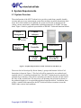
1
8888 University Drive
Burnaby, BC
Canada V5A 1S6
[email protected]
www.mfclabs.com
small innovations
for big solutions™
February 22, 2005
Mr. Lucky One
School of Engineering Science
Simon Fraser University
Burnaby, British Columbia
V5A 1S6
Re: ENSC 440 Functional Specifications for a Micro Fuel Cell Testbench
Dear Mr. One:
Please find attached the document, Functional Specifications for a Micro Fuel Cell
Testbench, outlining the functionality of our product for ENSC 440. The purpose of
the product is to allow a researcher to perform rigorous testing on his or her design
of a novel micro fuel cell. The testbench shall perform real-time data acquisition of
the micro fuel cell operating parameters and shall be capable of operating as a
stand-alone system which can be used to demonstrate the micro fuel cell for
consumers and potential investors.
The attached document outlines in detail the required functionality of the prototype
and additional features for future versions of the product. The functional
requirements are discussed for the system as a whole and for its components
separately. The document also provides information on requirements for the user as
well as safety and regulatory requirements for our product.
Our team includes four talented individuals with expertise in various technical
fields. The members of our team are Arash Jamshidi, Sarang Toosi, Olha Lui, and
Shirin Farrahi. Please feel free to contact us at by e-mail at [email protected] for
more information regarding our project.
Sincerely,
Shirin Farrahi
Shirin Farrahi
Chief Executive Officer (CEO)
Micro Fuel Cell Labs (MFC Labs)
Enclosure: Functional Specifications for a Micro Fuel Cell Testbench
Functional Specifications for
a Micro Fuel Cell Testbench
Project Team
Arash Jamshidi
Olha Lui
Sarang Toosi
Shirin Farrahi
Contact person
Shirin Farrahi
[email protected]
Submitted to
Lucky One – ENSC 440
Mike Sjoerdsma – ENSC 305
School of Engineering Science
Simon Fraser University
Date: February 22, 2005
```
Executive Summary
MFC Labs recognizes the increasing need for convenient, long-lasting power for portable
electronics equipment. Our company believes that micro fuel cell technology shows
great potential for solving many of the problems with current portable power solutions
including weight, recharging requirements, and lifetime. Our product, the MFC
Testbench, is meant to address fuel cell researchers’ need for a cheap and portable device
for testing micro fuel cells. The MFC Testbench will allow for accurate and exhaustive
characterization of a micro fuel cell’s characteristics while also being a useful tool for
demonstrating the fuel cell’s operation to potential investors at tradeshows. The
prototype of our product will be completed by the end of April 2005 and will
immediately be put into use for testing the micro fuel cell developed by the National
Research Council of Canada’s (NRC) Institute for Fuel Cell Innovation (IFCI).
To be useful and competitive to current test equipment on the market, the MFC
Testbench must meet a number of functional requirements. In our functional
specifications we outline these requirements including
1. The capability to use power from a battery or AC adaptor.
2. The ability to log test data to a computer via a graphical user interface.
3. The ability to vary the load seen by the fuel cell manually and using a
computer.
In addition, we have outlined requirements for the accuracies and ranges of current,
voltage, temperature, and humidity measurements available from our test station; the
reliability of our unit; and the portability and ease of use offered. We also specify our
expectations of the user as well as safety and regulatory requirements which must be
upheld by our design and by the users. In addition to specifying requirements for the
development of the prototype, the functional specifications also specify requirements for
the next stage of the project including
1. A rechargeable battery source.
2. Enhanced user functions offered by the graphical user interface program.
3. Flow monitoring and control equipment to regulate the supply of methanol to
the device under test (DUT).
The functional specifications presented will serve as an agreement with our customers on
the functionality of our product and as a guide for the MFC Labs team in product design
and development.
Copyright © 2005 MFC Labs
ii
```
Table of Contents
EXECUTIVE SUMMARY ......................................................................................................................... II
TABLE OF CONTENTS ...........................................................................................................................III
TABLE OF FIGURES ...............................................................................................................................III
GLOSSARY ................................................................................................................................................ IV
1. INTRODUCTION .................................................................................................................................... 1
1.1 Scope......................................................................................................................... 1
1.2 Objective ................................................................................................................... 1
2. SYSTEM REQUIREMENTS.................................................................................................................. 2
2.1 System Overview ...................................................................................................... 2
2.2 Physical Requirements.............................................................................................. 3
2.3 System Requirements................................................................................................ 3
2.3.1 General ........................................................................................................................................ 4
2.3.2 Ranges and Accuracies of Controls and Measurements .............................................................. 4
2.3.3 Performance................................................................................................................................. 5
2.3.3 Power ........................................................................................................................................... 5
2.3.5 Reliability..................................................................................................................................... 5
2.4 User Expectations ..................................................................................................... 6
3. INTERFACE REQUIREMENTS........................................................................................................... 7
3.1 Onboard Interface Requirements .............................................................................. 7
3.1.1 General ........................................................................................................................................ 7
3.1.2 Onboard Display Requirements................................................................................................... 8
3.2 Graphical User Interface Requirements.................................................................... 8
3.2.1 Load Cycle File Requirements ..................................................................................................... 9
3.2.2 Data Logging Requirements ........................................................................................................ 9
3.4 DUT Interface Requirements.................................................................................. 10
4. REGULATORY REQUIREMENTS.................................................................................................... 10
5. DOCUMENTATION AND USER TRAINING................................................................................... 11
6. CONCLUSION....................................................................................................................................... 12
7. REFERENCES ....................................................................................................................................... 13
Table of Figures
FIGURE 1: GRAPHICAL REPRESENTATION OF MFC TESTBENCH SYSTEM BLOCKS [1]..................................... 2
FIGURE 2: FUNCTIONAL DIAGRAM OF ONBOARD DISPLAY CONTROL BUTTON ............................................... 7
Copyright © 2005 MFC Labs
iii
```
Glossary
AC
DMFC
DUT
GUI
MFC Testbench
MSDS
Alternating Current
Direct Methanol Fuel Cell
Device Under Test
Graphical User Interface
Micro Fuel Cell Testbench
Material Safety Data Sheet
Copyright © 2005 MFC Labs
iv
```
1. Introduction
The Micro Fuel Cell Testbench is a product in development that is intended for use in the
laboratory environment for rigorous testing of novel direct methanol fuel cells (DMFCs).
Additionally, the MFC Testbench will be able to operate as a stand-alone unit during
tradeshows. The main testing operations of the device will include monitoring the
operating voltage and current of the DMFC in response to variable load. The unit will
also monitor the ambient temperature and humidity while the fuel cell is operating. The
prototype of the MFC Testbench is currently under development with the intent of being
tested in a laboratory environment by April 2005.
1.1 Scope
This document provides detailed functional specifications for the prototype of the MFC
Testbench, as well as additional specifications intended for future versions of the product.
The functionality of the testbench is discussed for the system as a whole, as well as for its
components. In addition, separate sections address the expectations of the user of the
testbench, safety and regulatory requirements, and documentation and user training.
1.2 Objective
The requirements listed in this document are intended to outline the functional
specifications of the MFC Testbench to the potential users, as well as to guide the design
of the testbench.
The following convention is used throughout this document to denote functional
requirements:
R[#]-P Functional specifications requirement
#: Requirement Number
P: Priority of Requirement.
P can have one of the following values:
A – denotes a high priority requirement to be implemented for the proof of
concept device
B – denotes an enhanced feature to be implemented for the productionready device.
Copyright © 2005 MFC Labs
1
```
2. System Requirements
2.1 System Overview
The main function of the MFC Testbench is to provide a stand-alone, portable, durable,
accurate and easy-to-use measurement system that can help researchers demonstrate their
micro fuel cell in tradeshows. In addition, the system can be used to characterize the
voltage, current, temperature, and humidity operating parameters of a DMFC for many
hours. Figure 1 shows a graphical representation of the MFC Testbench functional blocks.
Power
Management
Control
Software
To internal
circuitry
Onboard
Display
Micro
Controller
Measurement
Variable
Load
Device Under
Test (DUT)
Figure 1: Graphical Representation of MFC Testbench System Blocks [1]
The micro fuel cell developed by Kevin Stanley’s group at the Institute for Fuel Cell
Innovation is shown in Figure 1. This fuel cell will be connected to our testbench and
supplied with a 5% solution of methanol fuel. The MFC Testbench can be controlled by
a graphical user interface (GUI) which can both log test data for the fuel cell and control
the value of the variable load. The micro fuel cell operating data will also be shown on
the testbench display as it is acquired through the measurement block. In addition, there
will be a variable load connected to the DUT which will allow researchers to test the
DMFC under various load conditions.
Copyright © 2005 MFC Labs
2
```
2.2 Physical Requirements
The main physical requirements of the MFC Testbench are that it be portable, imposing
restrictions on its weight, size, and connectivity requirements.
R[1]-A The testbench without the fuel cell, methanol supply, and electronic load
shall be no larger than 20cm x 10cm x 5cm.
R[2]-A The testbench without the fuel cell, methanol supply, and electronic load
shall weigh no more than 3 kg.
R[3]-A The testbench shall be suitable for safe transportation and easy assembly at
tradeshows (see sections 3 and 4 for more detailed specifications on
interface requirements and safety).
R[4]-A The testbench shall be stand-alone and capable of operating without a
computer connection.
R[5]-A The testbench shall be divided in two separate sections: fuel cell unit and
measurement unit.
R[6]-A The user shall have open access to the DUT for easy transferring during
testing and for visibility of the DUT during demonstrations.
R[7]-A The onboard display shall be mounted on top of the testbench.
R[8]-A The manual load control knob shall be accessible from the top of the
testbench.
R[9]-A The power jack, battery, and port for communication with the computer
shall be easily accessible.
R[10]-A The humidity and temperature monitoring equipment shall be located within
2 cm of the cathode of the DUT.
2.3 System Requirements
The MFC Testbench is intended for use in research and development; therefore, its main
requirements govern the accuracy of the controls and measurements which it can provide
and the reliability of the unit.
Copyright © 2005 MFC Labs
3
```
2.3.1 General
R[11]-A The testbench shall be capable of operating at temperatures between 0 to 40
ºC.
R[12]-A The testbench shall be equipped with two resistive loads: one manually
controlled and one controlled by the GUI.
R[13]-B A transient load analysis shall be provided for more rigorous testing of the
DUT.
R[14]-B The testbench shall have an onboard storage capability for storing data of
up to 50 kB.
2.3.2 Ranges and Accuracies of Controls and Measurements
The MFC Testbench must measure the current, voltage, temperature, and humidity of the
operating fuel cell with a specified accuracy. Similarly, the testbench should be capable
of controlling the manual and electronic load values in a specified range.
R[15]-A The tesbench shall provide the capability to test DUT operating voltages of
up to 2.00 V ± 0.05 [2].
R[16]-A The testbench shall be capable of varying the electronic computercontrolled resistive load bank in the range of 1 Ω to 1 kΩ when used in the
constant resistance mode, with a maximum power dissipation of 1 W.
R[17]-A The manual variable load shall be capable of varying in the range of 1 Ω to
50 kΩ, where 0.5 W is the maximum power dissipation.
R[18]-A The maximum current flowing through the load shall be 1 A [3].
R[19]-A The testbench shall be capable of detecting and displaying humidity in the
range of 1 to 90 % RH ± 3 based on the ambient humidity of the
environment [2].
R[20]-A The testbench shall be capable of detecting and displaying temperatures in
the range of 0 to 100 ºC ± 1 [2].
R[21]-B The flow rate monitoring equipment shall be capable of operating in the
range of 20 - 100 mL/min with an accuracy of 10% full scale.
Copyright © 2005 MFC Labs
4
```
2.3.3 Performance
R[22]-A The response time of the onboard display to changes in the voltage, current,
humidity and temperature sensors shall have an upper limit of 500 ms.
R[23]-A The response time of the onboard display to display control commands shall
have an upper limit of 1 s.
R[24]-A The response time of the GUI program to the user pressing the “Exit”
button shall be less than 1 s.
2.3.3 Power
To ensure portability and convenience of the MFC Testbench, it shall have the option of
being powered from a portable AC adaptor or from a battery.
R[25]-A The testbench shall be capable of being powered by a 110 V, 60 Hz AC
adaptor which can operate in the range 0 to 50 ºC.
R[26]-A The onboard battery shall be capable of operating in the range 0 to 40 ºC.
R[27]-A The battery shall be capable of powering the testbench for a minimum of
eight (8) hours continuously.
R[28]-B The battery shall be rechargeable.
2.3.5 Reliability
The MFC Testbench is required for long-term, unsupervised testing of the DMFC;
therefore, the unit must be capable of operating without failure over long periods of time.
R[29]-A When powered by the AC adaptor, the unit must be capable of monitoring
the DUT’s operating voltage, current, temperature, and humidity for up to
720 hours (30 days) without failing.
R[30]-A If the user interface program detects a current, voltage, temperature, or
humidity outside of the ranges specified in section 2.3.2, a warning message
will be displayed, and the test cycle will terminate.
R[31]-A If the load value specified in a row of the Load Cycle file is outside of the
range specified in section 2.3.2, the user interface program shall display a
warning message and end the current test cycle.
Copyright © 2005 MFC Labs
5
```
R[32]-B If the onboard controller detects a current, voltage, temperature, or humidity
reading outside of the ranges specified in section 2.3.2, a warning message
will be displayed, and the controller will stop taking measurements.
R[33]-A The testbench must be able to recover from a potential failure if the user
resets the unit using the power switch.
R[34]-A The testbench shall have a mean time between failures (MTBF) of at least
50,000 hours.
R[35]-A The testbench shall be serviceable by the end user.
R[36]-A The onboard display control switch shall have a duty cycle of 200,000
cycles for each direction [1].
R[37]-A The onboard power switch and load toggling switch shall have a duty cycle
of 100,000 cycles each.
2.4 User Expectations
Due to the dependence of the MFC Testbench operation on the user’s fuel cell, a large
number of requirements are placed on the user in order to operate the unit properly.
R[38]-A The user shall provide a 5 % methanol-water solution housed in a
pressurized tank and tubing to supply the methanol to the DUT.
R[39]-A The user shall provide the necessary enclosures, connectors, tubing, and
supply tank for the fuel cell and methanol fuel supply.
R[40]-A The user shall provide the tubing for the waste outlets of the DUT and the
waste collecting containers.
R[41]-A The user shall be responsible for the safe disposal of the waste (see section
4 for more detailed safety requirements).
R[42]-A The user shall be responsible for recording flow rates of interest during the
operation of the testbench.
R[43]-A The user shall be responsible for arranging the means for controlling the
rate of fluid flow.
R[44]-A The user shall supply a computer capable of running the user interface
program and storing a data cycle file of up to 128 MB in capacity.
Copyright © 2005 MFC Labs
6
```
3. Interface Requirements
3.1 Onboard Interface Requirements
The MFC Testbench onboard interface shall include two switches, a display, a joystick
button to control the display, and a dial for controlling load values.
3.1.1 General
R[45]-A The testbench shall have an on/off power switch.
R[46]-A There shall be a single onboard button to allow the user to toggle between
the DUT operating display options.
R[47]-A The onboard button will allow the user to scroll through the menu options in
four directions or select an option by pressing down on it as shown in
Figure 2.
Figure 2: Functional Diagram of Onboard Display Control Button
R[48]-A The onboard manual load control will allow the user to vary the load using
a rotary dial.
R[49]-A There shall be an onboard switch to allow the user to switch between
manual and computer-controlled load.
R[50]-A The user shall have to turn off the testbench’s power before switching
between manual and computer-controlled load then power up the system
again before the change takes effect.
R[51]-B Flow rate monitoring equipment shall provide a visual means of monitoring
the flow rate of methanol to the DUT.
Copyright © 2005 MFC Labs
7
```
3.1.2 Onboard Display Requirements
The onboard display shall provide the user with a single-line display to view the
operating parameters of the DUT including absolute time and date, voltage, current,
temperature, and humidity values. The ranges and accuracies of these display values are
outlined in section 2.3.2. When the MFC Testbench is turned on, the user will be able to
scroll through the display options menu as described below.
R[52]-A The top level of the menu shall display a welcome message. The lower
levels of the menu shall allow the user to view the DUT’s operating
parameters.
R[53]-A The date and time level of the menu shall allow the user to scroll between
the current time and current date.
R[54]-A Current time will be displayed in the format “hh:mm:ss”. Current date will
displayed in the format “dd:mm:yy”.
R[55]-A The date and time level of the menu shall allow the user to adjust the
current time and current date settings using the onboard button.
R[56]-A The voltage level of the display menu shall display the voltage in the format
“3V25” where the symbol “V” represents the decimal point position.
R[57]-A The current level of the display menu shall display the current in the format
“100mA” where the symbol “mA” shall display the decimal point position.
R[58]-A The humidity level of the display menu shall display the humidity in the
format “20RH” where “RH” means percentage of the relative humidity.
R[59]-A The temperature level of the display menu shall display the temperature in
the format “+24°C”/”+75°F” where the user can toggle between Celsius and
Fahrenheit units.
3.2 Graphical User Interface Requirements
The Graphical User Interface will present the user with controls and indicators for
controlling the MFC Testbench remotely and logging test data automatically.
R[60]-A The user shall have the option of exiting the program at any point of its
operation by pressing a button.
R[61]-A The user shall be presented with dedicated buttons for beginning or ending
a test cycle.
Copyright © 2005 MFC Labs
8
```
R[62]-B The user shall be presented with a button allowing him or her to
pause/resume a test cycle.
R[63]-A After choosing to start a test cycle, the user shall be able to choose whether
or not to enter a pre-determined Load Cycle file.
R[64]-A If the user begins a test cycle without entering a Load Cycle file, the user
interface program will log data without modifying the load seen by the fuel
cell.
R[65]-B If the user begins a test cycle without entering a Load Cycle file, he or she
will be able to vary the load manually on the testbench.
R[66]-B In the case where a Load Cycle file is not entered, the user shall have the
ability to control the load interactively using a virtual dial control in the
control software.
3.2.1 Load Cycle File Requirements
R[67]-A The user shall be able to browse the computer’s existing files from the GUI
program to find the desired Load Cycle file.
R[68]-A The Load Cycle file shall contain as many rows as the distinct loads that the
user wants to apply to the fuel cell.
R[69]-A Each row in the Load Cycle file shall contain two columns, one specifying
the load value, and one specifying the duration of time for which the load
should be applied.
3.2.2 Data Logging Requirements
When a test cycle is initiated, the DUT operating parameters (current, voltage,
temperature, humidity) will be obtained periodically by the user interface program.
R[70]-A The shortest time interval between consecutive data samples by the user
interface program shall be 10 s.
R[71]-B The user shall be able to vary the period of data uploading by entering a
value between 10 s and 1 hour as the test cycle is operating.
R[72]-A The ten (10) most recent data instances shall be displayed in a table on the
computer screen.
R[73]-A All data instances shall be stored in a Data Log file.
Copyright © 2005 MFC Labs
9
```
R[74]-A The Data Log file shall have one row for each data instance.
R[75]-A Each row in the Data Log file shall consist of seven (7) columns: absolute
date, absolute time, time since beginning of test cycle, operating current,
operating voltage, operating temperature, and operating humidity.
3.4 DUT Interface Requirements
The DUT shall be fueled by a methanol-water solution and air. Refer to section 2.4 for
more details regarding the equipment supplying the fuels.
R[76]-A The fuel cell and measurement sections of the MFC Testbench shall be
connected through a protected electrical interface.
R[77]-B Flow rate monitoring equipment shall be incorporated in the line of flow of
the methanol.
R[78]-B The flow rate monitoring equipment shall have fluid touching parts and
outlet tubing which are chemically inert to the 5% methanol-water solution.
R[79]-B The flow rate monitoring equipment shall be able to operate at fluid
temperatures of up to 35 ºC at 0 pressure.
R[80]-B The flow rate monitoring equipment and the tubing shall be able to operate
at a maximum fluid pressure of 75 psig at 21 ºC.
R[81]-B The flow rate monitoring equipment and the tubing shall be capable of
operating with fluid containing debris of up to 50 microns in size.
4. Regulatory Requirements
The safety and regulatory requirement for the MFC Testbench address the issues related
to methanol handling, the fuel cell operation, and the electronic components.
R[82]-A The testbench shall operate within the Safety Requirements for Electrical
Equipment for Measurement in Control and Laboratory Use [4].
R[83]-A The testbench shall operate within the safety standards established by CSA
International Requirement No. 3.01 for Portable Fuel Cell Appliances [5].
R[84]-A The testbench shall operate within the safety standards established by
ANSI/CSA America FC 1-2004, Stationary Fuel Cell Power Systems,
where they deal with methanol [6].
Copyright © 2005 MFC Labs
10
```
R[85]-A The testbench fluidic handling parts shall exclude materials which are
chemically reactive with methanol, as advised by its Material Safety Data
Sheet (MSDS) [7].
R[86]-A The user shall transport the DUT and methanol handling equipment
according to the safety standards established by the Canadian DTG:
Methanol, Flammable Liquid [8].
R[87]-A The user shall handle the DUT and methanol according to the safety
standards and recommendations established by WHMIS-Canada and the
Canada Safety Council [8], [10].
R[88]-A The user shall educate himself on issues related to DMFC safety standards
currently in development, such as USA (CSA FC 3) Portable Fuel Cell
Power Systems and Canada Portable Fuel Cell Standard [9].
R[89]-A The testbench unit shall be safely constructed without any sharp or fragile
parts.
R[90]-A The electronic parts of the testbench shall be separated from the methanol
handling parts where it does not contradict with functionality.
5. Documentation and User Training
The intended user for the MFC Testbench is a researcher who is working on a direct
methanol fuel cell. It is expected that the user has sufficient technical background and
skills to set up the testbench with the DUT, perform the test, and interpret the results.
R[91]-A The documentation for the product will consist of one user manual in
English.
R[92]-A The user manual will have information on functionality of the device,
operating conditions, instructions for interfacing the device to the DUT,
methanol supply, requirements for the user’s computer, and a set of sample
test instructions.
R[93]-A The user manual will provide suggestions on how to expand the hardware
components and how to upgrade the software of the product.
R[94]-A The user manual will also include a troubleshooting section and a safety
section.
R[95]-A The company’s website, www.mfclabs.com, shall be a source of brief
technical information about the product, downloadable whitesheets, and
FAQ information on the functionality and operation of the device.
Copyright © 2005 MFC Labs
11
```
R[96]-A Training for the end users will be provided via the user manual and by
contacting the technical support by e-mail at [email protected].
R[97]-A The users of the prototype version of the product will meet with the project
developers for initial training on interfacing the DUT to the testbench and
on testing the DUT.
6. Conclusion
The functional specifications outlined in this document are detailed and demanding. We
have created this challenge for ourselves intentionally to ensure we can meet the high
demands of researchers in the field of micro fuel cells, and to push ourselves to develop a
product that will set a new standard for cheap, reliable, and portable DMFC test
equipment. The specifications for the system and its components will allow us to design
an expandable testbench and to allocate our time and resources efficiently. We intend to
develop the functionality identified as required for the prototype by the end of April 2005.
Copyright © 2005 MFC Labs
12
```
7. References
[1] Atmel Corporation Products, 2005, “AVR Butterfly”, 23 January 2005
<http://www.atmel.com/dyn/products/tools_card.asp?tool_id=3146>
[2] Niroumand, A. “Micro Direct Methanol Fuel Cell Test Station” Dec. 2004.
[3] Stanley, K.; Czyzewska, E. et. al. “A Novel Fabrication Method for Micro Fuel
Cells.”
[4] “Safety Requirements for Electrical Equipment for Measurement, Control, and
Laboratory Use” CAN/CSA-C22.2 NO. 61010-1-04 Canadian Standards
Association, 2001. Accessed on February 21, 2005 at
<http://www.csa.ca/electronic_catalogue/electrical.pdf>
[5] “International Requirement No. 3.01 For Portable Fuel Cell Appliances.” Canadian
Standard Association, August 2001. Accessed on February 19, 2005 at
<http://www.fuelcellstandards.com/2.1.3.13.htm>.
[6] “Stationary Fuel Cell Power Systems.” ANSI/CSA America FC, February 2004.
Accessed on February 19. 2005 at
<http://www.fuelcellstandards.com/2.1.3.1.htm>
[7] “Material Safety Data Sheet for Methanol” Methanex Corporation, Dec. 10, 2002.
Accessed on February 21, 2005 at
<http://www.methanex.com/products/documents/MSDS_CANenglish.pdf>.
[8] “Technical and Safety Data for Methanol.” Methanex Corporation. Accessed on
February 21, 2005 at <http://www.methanex.com/products/technical.html>.
[9] “Portable Fuel Cell Power Systems and Canada Portable Fuel Cell Standard.” CSA
FC 3. Canadian Standards Association. Accessed on February 21, 2005 at
<http://www.fuelcellstandards.com/2.1.3.3.htm>.
[10] “Methanol” Canada Safety Council, 2004. Accessed on February 21, 2005 at
<http://www.safety-council.org/info/OSH/methanol.htm>.
Copyright © 2005 MFC Labs
13