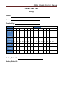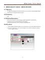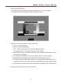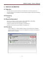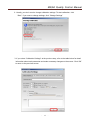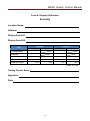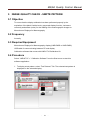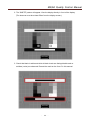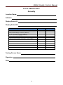
1
MQSA Quality Control Manual
MQSA Quality Control Manual
for
Monochrome Displays
for Mammography
Ver1.0
Applicable Models
LMD-DM50, LMD-DM30
Sony Corporation
-
1 -
MQSA Quality Control Manual
MQSA Quality Control Manual
for
Monochrome Displays for Mammography
Foreword
Purpose of this Document
This document is for Monochrome Displays for Mammography, diagnostic displays to perform the Quality
Control (QC) tests to meet the guidelines / regulations of Mammography Quality Standards Act (MQSA)
for the reading of the digital mammographic images. This document describes the procedure for
performing the Quality Control (QC) tests for Monochrome Displays for Mammography, diagnostic
displays based on the guidelines / regulations of Mammography Quality Standards Act (MQSA).
Scope of this Manual
This document is referenced when conducting the Quality Control (QC) tests to Monochrome Displays for
Mammography, diagnostic displays based on the guidelines / regulations of Mammography Quality
Standards Act (MQSA) for the reading of the digital mammographic images through the full-field digital
mammography (FFDAM) system.
Regulatory Considerations
For the facilities under the MQSA regulations, application of this manual is MANDATORY.
Failure to follow these quality assurance procedures can result in loss of MQSA certification at facilities
subject to the MQSA regulations. For the facilities under the MQSA guidelines, application of this manual
is RECOMMENDED. Otherwise, the facilities may identify other ways of meeting MQSA requirements.
Applicable Models
LMD-DM50, LMD-DM30
-
2 -
MQSA Quality Control Manual
Contents
Foreword ............................................................................................................................................2
Contents .............................................................................................................................................3
Installation ........................................................................................................................................5
Chapter 1: QC TESTS FOR THE RADIOLOGIC TECHNOLOGIST
1 Introduction ..................................................................................................................................6
2 Intervals for Procedures .............................................................................................................6
3
Cleaning Display ..........................................................................................................................7
3.1 Objective ................................................................................................................................7
3.2 Frequency ..............................................................................................................................7
3.3
Required Equipment .............................................................................................................7
3.4 Procedure ...............................................................................................................................7
4
Viewing Conditions Check ..........................................................................................................8
4.1 Objective ................................................................................................................................8
4.2 Frequency ..............................................................................................................................8
4.3
Required Equipment .............................................................................................................8
4.4 Procedure ...............................................................................................................................8
Form 1: Daily Test .........................................................................................................................9
5 Image Quality Check - SMPTE pattern.....................................................................................10
5.1 Objective ..............................................................................................................................10
5.2 Frequency ............................................................................................................................10
5.3
Required Equipment ...........................................................................................................10
5.4 Procedure .............................................................................................................................10
Form 2: SMPTE Pattern...............................................................................................................12
Chapter 2: QC TESTS FOR THE MEDICAL PHYSICIST
1 Introduction ................................................................................................................................13
2 Intervals for Procedures ...........................................................................................................13
3
Viewing Conditions Check and Setting ...................................................................................14
3.1 Objective ..............................................................................................................................14
3.2 Frequency ............................................................................................................................14
3.3
Required Equipment ...........................................................................................................14
3.4 Procedure .............................................................................................................................14
Form 3: Viewing Condition Check and Setting ..............................................................................15
-
3 -
MQSA Quality Control Manual
4
Display Calibration .................................................................................................................16
4.1
Objective
...........................................................................................................................16
4.2
Frequency
.........................................................................................................................16
4.3
Required Equipment
4.4
Procedure
........................................................................................................16
..........................................................................................................................16
Form 4: Display Calibration........................................................................................................20
5 Image Quality Check – SMPTE pattern ...................................................................................21
5.1 Objective ..............................................................................................................................21
5.2 Frequency ............................................................................................................................21
5.3
Required Equipment ...........................................................................................................21
5.4
Procedure
..........................................................................................................................21
Form 5: SMPTE Pattern...............................................................................................................25
Definition .......................................................................................................................................26
-
4 -
MQSA Quality Control Manual
INSTALLATION
Connecting the cables
Follow the instructions in the display manual to properly connect the communication
cable supplied with the display.
Installing calibration software and sensor driver
Install the calibration software “Display Calibrator software” and sensor driver into the
workstation.
-
5 -
MQSA Quality Control Manual
Chapter 1: QC TESTS FOR THE RADIOLOGIC
TECHNOLOGIST
1
INTRODUCTION
QC tests that are listed in this section are to provide the procedure for maintaining Monochrome
Displays for Mammography, diagnostic displays in its designed optimal quality conditions by
keeping the displays free of any image quality deterioration and by performing the regular
viewing conditions and image quality checks.
QC tests for the diagnostic display are described in the following sections:
• Section 3: Cleaning Display
• Section 4: Viewing Conditions Check
• Section 5: Image Quality Check - SMPTE pattern
2
INTERVALS FOR PROCEDURES
The table below shows intervals for each procedure described in this manual.
Procedure
Interval
Cleaning Display
Daily
Viewing Condition
Daily
Image Quality Check – SMPTE pattern
Daily
-
6 -
MQSA Quality Control Manual
3
CLEANING DISPLAY
3.1 Objective
To maintain the screen, clean by keeping the display screen free from any objects (dust,
finger print, etc.) of the display of Monochrome Displays for Mammography
3.2 Frequency
Daily
3.3 Required Equipment
Lint free cloth
3.4 Procedure
Note: The cabinet is made of plastic and coated metal plate. Do not apply thinner, benzene,
or alcohol. It could damage the plastic and/or the coating could come off.
1. When cleaning the display, remove the AC adaptor from the display and the wall outlet for
your safety.
2. Dampen the lint free cloth with cleaning agent designed specifically for cleaning
Computer Displays and remove the dust gently. Finish up by wiping with the dry cloth.
3. Clean the LCD panel (protective filter) and the surface periodically with a dampened soft
cloth.
4. Record the result on the form 1 in this manual.
Note: Do not use Windex or household cleaners which can damage the Display’s AR
coating.
Note: Be careful when handling the LCD panel (protective filter). Do not rub or hit with sharp
or hard objects. Do not press on the panel. It could cause unevenness in luminance or
damage the panel.
-
7 -
MQSA Quality Control Manual
4
VIEWING CONDITIONS CHECK
4.1 Objective
To keep and maintain the optimal viewing conditions on Monochrome Displays for
Mammography
4.2 Frequency
Daily
4.3 Required Equipment
Monochrome Displays for Mammography, display (LMD-DM50 or LMD-DM30)
USB cable for communicating between PC and display.
4.4 Procedure
1. Review the data form “Form 3: Viewing Conditions Check and Setting” on P15 (completed
by the Medical Physicist during the most recent evaluation) posted in the reading room.
Refer this form as optimal during your future evaluation.
2. Match the room configuration where each display is located to the one specified in the
data form.
3. Adjust the room configuration if the current reading room configuration differs from the
one established as optimal in the data form. (For example, if desk lights were specified to
be turned off, turn them off, or, if curtains were specified to be closed, close them.)
4. Complete the record of the check on the form 1 in this manual.
-
8 -
MQSA Quality Control Manual
Form 1: Daily Test
Daily
Facility:
Room:
Checked by:
Year
Date
Month
1
2
3
4
5
6
7
8
9
10
11
12
13
14
15
17
18
19
20
21
22
23
24
25
26
27
28
29
30
31
Initial
Cleaning
Display
Viewing
Conditions
Date
Initial
Cleaning
Display
Viewing
Conditions
Display Serial #1:
Display Serial #2:
-
9 -
16
MQSA Quality Control Manual
5
IMAGE QUALITY CHECK - SMPTE PATTERN
5.1 Objective
To calibrate the displays as accurate as possible for the reading of mammographic images
on Monochrome Displays for Mammography
5.2 Frequency
Daily
5.3 Required Equipment
Monochrome Displays for Mammography, display (LMD-DM50 or LMD-DM-30)
USB cable for communicating between PC and display
Calibration software that comes with LMD-KT10 Calibration Kit
5.4 Procedure
1. Select “Display Calibrator software” from the Start menu to start this software application.
2. Select the “Test Patterns” Tab. Click the display icon to choose the display to test and
click the “SMPTE” pattern.
-
10 -
MQSA Quality Control Manual
3. Check the SMPTE pattern.
The “SMPTE” pattern will appear. View the display directly in front of the display.
(The observer must be at least 50cm from the display screen.)
4. Visibility of the following features must be examined.
a. The 0 - 5% contrast pattern
b. The 95 - 100% contrast pattern
c. The 0 - 100% each gray level step from the adjacent squares
(For example: the 0 - 10% square or the 90 - 100% square)
d. The borders and lines of the pattern and that they are straight and the pattern is in the
active area of the display
e. No distortion and misalignment using the grids across the screen (Linearity)
f. The sharpness of the alphanumeric characters and that they are in focus
g. The high contrast line-pair images (each line in vertical and horizontal stripes in the
square) at the center and on the corners of the SMPTE pattern without magnification
h. The streaking in and around the white and the black rectangles (Video Characteristic)
5. Records the results on the form 2 in this manual.
-
11 -
MQSA Quality Control Manual
Form 2: SMPTE Pattern
Daily
Location Name:
Address:
Display Serial #1:
Display Serial #2:
Test
Display #1
Display #2
0%-5% contrast
95%-100% contrast
Gray level steps
Boarders, lines, centering
Linearity
Alphanumerics
Line-pair images (center)
Line-pair images (corners)
Video Characteristics
(Pass or Fail)
Testing Person Name:
Signature:
Date:
-
12 -
MQSA Quality Control Manual
Chapter 2: QC TESTS FOR THE MEDICAL PHYSICIST
1
INTRODUCTION
The QC tests listed in this section must be performed by the Medical Physicist to ensure that the
diagnostic display of Monochrome Displays for Mammography is operating in its optimal and
highest quality standard. These tests also must be performed when a major change that possibly
causes the change to its viewing quality and to its viewing performance such as the installation
of a new diagnostic display of Monochrome Displays for Mammography, the repair or
replacement of a major component of the system, or relocation of the diagnostic display
happens.
QC tests for the diagnostic display are described in the following sections:
• Section 3: Viewing Conditions Check and Setting
• Section 4: Display Calibration
• Section 5: Image Quality Check – SMPTE pattern
2
INTERVALS FOR PROCEDURES
The table below shows intervals for each procedure described in this manual.
Procedure
Interval
Viewing Condition Check and Setting
Annually
Display Calibration
Annually
Image Quality Check – SMPTE Pattern
Annually
-
13 -
MQSA Quality Control Manual
3
VIEWING CONDITIONS CHECK AND SETTING
3.1 Objective
To keep and maintain the optimal viewing conditions on Monochrome Displays for
Mammography
3.2 Frequency
Annually
3.3 Required Equipment
Illuminance Meter
3.4 Procedure
Before the measurement:
• Turn on displays for at least 60 minutes before starting measurement.
• Reduce any lighting coming from other sources such as viewboxes, over head or task
lighting to the minimum and check that the ambient lighting is stable (no flickering effect
due to any of the lighting sources that are turned on).
1. Make each display as dark as possible. (For example, by minimizing the application
windows or displaying a black flat field)
2. Measure the illuminance. (Face the photometer away from the surface of the display
screen during the illuminance measurement.)
3. Check that the measured illuminance value does not exceed 20 lux. (Adjust the room
ambient light and/or the room configuration to maintain the illuminance value under the
limit if it exceeds.)
4. Fill out the display positions, room lights, desk lights, etc. established as optimal on the
form 3 in this manual.
(Note: This data form will be referred by the Radiologic Technologist as optimal during their
daily “VIEWING CONDITIONS CHECK” on the page 8.)
5. Record the ambient light value on the form 3 in this manual.
6. Draw a room layout sufficiently accurate on the form in this manual, so that the Radiologic
Technologist can reproduce the illumination conditions established as optimal during their
daily “VIEWING CONDITIONS CHECK”.
7. Post the form in the reading room, so that the Radiologic Technologist can easily access
and refer during their daily “VIEWING CONDITIONS CHECK”.
8. Restore each display to its normal condition, i.e., undo any measures taken in Step 3.4.1
to darken the display.
-
14 -
MQSA Quality Control Manual
Form 3: Viewing Conditions Check and Setting
Annually
Facility:
Room:
Date:
Room Description
Display Positions:
Room Lights:
Desk Lights:
Others:
Ambient Light value:
Note: Confirmation of this value is not part of the daily check by the Radiologist
Technologist.
Important: The ambient light level must not exceed 20 lux.
Room Layout
Note: Draw sufficiently accurate for the Radiologic Technologist.
※
Post this form in the reading room for the Radiologic Technologist’s daily
“VIEWING CONDITIONS CHECK”.
-
15 -
MQSA Quality Control Manual
4
DISPLAY CALIBRATION
4.1 Objective
To ensure that an accurate evaluation of the display will be conducted to perform an
accurate calibration for the reading of the mammographic images on Monochrome Displays
for Mammography
4.2 Frequency
Annually
4.3 Required Equipment
Monochrome Displays for Mammography, display (LMD-DM50 or LMD-DM30)
USB cable for communicating between PC and display
Calibration software that comes with LMD-KT10 Calibration Kit
Calibration sensor that comes with LMD-KT10 Calibration Kit
4.4 Procedure
1. Select “LMD-KT10” > “Display Calibrator software” from the Start menu of Windows.
Attach the calibration sensor to center of the displayed box as shown on the display to
calibrate and click “Calibration”.
-
16 -
MQSA Quality Control Manual
2. Usually, you don’t need to change calibration settings. To start calibration, click
“Start”. If you want to change settings, click “Change Settings”
3. If you select “Calibration Settings” at the previous step, refer to the table below for detail
information about each parameter and make necessary changes on the screen. Click “OK”
to return to the previous screen.
-
17 -
MQSA Quality Control Manual
Setting
Explanation
Maximum Luminance
The target brightest luminance. Use the default value
of 410 cd/m2 or 500 cd/m2 (display’s factory default)
unless otherwise necessary.
Important: Maximum luminance is settable within the
range specified on the wizard. However, due to
luminance degradation caused by deterioration of
the backlight, the result may fall short of the target
luminance.
Minimum Luminance
The target darkest luminance. Use the default value of
0.8 cd/m2 unless otherwise necessary.
Ambient Light
The effects of ambient light. Enter the value only if it is
known, otherwise leave it as is.
Hint:The current ambient light can be measured by
clicking the Measure button. (Except for ME511L)
Gamma Setting
Comment
Gamma setting should be DICOM GSDF
(Recommended)
Add a comment at the time of adjustment for later
reference. This can be left blank.
4. Record the Gamma setting, max. luminance, min. luminance and ambient light
(optional) value of each display set at on the Form 4 in this manual.
-
18 -
MQSA Quality Control Manual
5. When calibration is completed, the “Finishing Calibration” window is displayed with the
results. Click “Show Details” to display graphical outputs.
-
19 -
MQSA Quality Control Manual
Form 4: Display Calibration
Annually
Location Name:
Address:
Display Serial #1:
Display Serial #2:
Test
Display #1
Setting
Display #2
Result
Setting
Result
Configuration
Gamma
Max. Luminance
cd/m2
cd/m2
cd/m2
cd/m2
Min. Luminance
cd/m2
cd/m2
cd/m2
cd/m2
Ambient Light
cd/m2
cd/m2
cd/m2
cd/m2
(Pass or Fail)
Testing Person Name:
Signature:
Date:
-
20 -
MQSA Quality Control Manual
5
IMAGE QUALITY CHECK - SMPTE PATTERN
5.1 Objective
To ensure that the display calibration has been performed properly by the
evaluation of the black & white levels, gray-scale display function, luminance
uniformity and artifact (noise) for the reading of the mammographic images on
Monochrome Displays for Mammography
5.2 Frequency
Annually
5.3 Required Equipment
Monochrome Displays for Mammography, display (LMD-DM50 or LMD-DM30)
USB cable for communicating between PC and display
Calibration software that comes with LMD-KT10 Calibration Kit
5.4 Procedure
Select “LMD-KT10” > “ Calibration Software” from the Start menu to start this
software application.
1. To display a test pattern, select “Test Patterns” Tab. The selected test pattern is
displayed on the selected display.
-
21 -
MQSA Quality Control Manual
2. The “SMPTE” pattern will appear. View the display directly in front of the display.
(The observer must be at least 50cm from the display screen.)
3. Check that black-in-white and white-in-black levels are distinguishable and no
artifacts (noise) are observed. Record the result on the form 5 in this manual.
-
22 -
MQSA Quality Control Manual
4. Check that each gray-scale pattern and 0 - 5% & 95 - 100% contrasts are
distinguishable and no artifacts (noise) are observed. Record the result on the
form 5 in this manual.
5. Go back to the main screen of “Test Patterns”, and select ‘’TG-18-UN80”. If you
don’t see the main screen, just click anywhere on the test pattern to recall it.
-
23 -
MQSA Quality Control Manual
6. The “TG18-UN80” pattern will appear. View the display directly in front of the display. (The
observer must be at least 50cm from the display screen.)
7. Check that luminance non-uniformity is not observed from the center to the edges.
Record the result on the form 5 in this manual.
-
24 -
MQSA Quality Control Manual
Form 5: SMPTE Pattern
Annually
Location Name:
Address:
Display Serial #1:
Display Serial #2:
Test
Display #1
Display #2
Black-in-White & White-in-Black Levels (SMPTE)
Gray-Scale Display Function (SMPTE)
5-10%, 95-100% contrast (SMPTE)
Artifact (Noise) (SMPTE)
Luminance Uniformity (All White / TG18-UN80)
(Pass or Fail)
Testing Person Name:
Signature:
Date:
-
25 -
MQSA Quality Control Manual
DEFINITION
SMPTE
Society of Motion Picture and Television Engineers, Inc.
Display Calibrator
Software
Calibration software application
Display Quality
Controller
Quality assurance software application
MQSA
Mammography Quality Standards Act
FFDM
Full-Field Digital Mammography
AAPM TG18
American Association of Physicists in Medicine, Task Group 18
Chroma5
x-rite calibration sensor
DICOM
Digital Imaging and Communications in Medicine
GSDF
Grayscale Standard Display Function
JND
Just Noticeable Difference
lux
One lux is the illuminance at the same point at a distance of 1
meter from the source. One lumen uniformly distributed over
one square foot of surface provides an illumination of 1
foot-candle.
-
26 -
MQSA Quality Control Manual
Notes for the User's Manual
• No part of this manual, whether partly or wholly, may be reproduced or copied without authorization.
• The content of this manual is subject to change without notice.
• Although this manual has been prepared carefully, please let us know if you find any errors,
omissions, or ambiguous explanations.
Sony Corporation
1-7-1 Konan, Minato-ku, Tokyo, 108-0075 Japan.
-
27 -