1
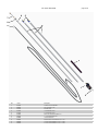
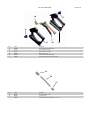
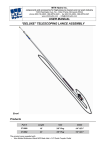
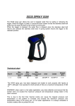
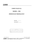
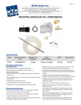
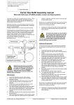
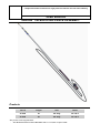
components and accessories for high pressure cleaners and car wash industry USER MANUAL “DELUXE” TELESCOPING LANCE ASSEMBLY Products Part # Lenght Inlet Outlet 27.0080 18’ 3/8” Plug 1/4" QC F 27.0082 24’ 3/8” Plug 1/4" QC F The product come supplied with: - Non Molded Extension Wand M22 Male Inlet x 1/4” Quick Coupler Outlet last update: 20-07-2012 page 2 of 6 Product’s use Use fresh and clear water, with common detergents. We also recommend that any impure fluid be adequately filtered before it is used. Use the correct size nozzle for the flow and pressure of the unit the lance is being installed on and with the trigger pulled carefully adjust the unloader to obtain the correct working pressure. This will avoid dangerous pressure spikes in the system. The product will allow for the use of hot water (see Technical Chart). Check that the lance is compatible with the system’s functioning data in order to not exceed the maximum values of pressure and temperature. Fits gas and electric pressure washer rated up to 4000 PSI. Warnings and cautions Beware of overhead power lines. Contacting these lines may result in electrocution, injury, or even death. Always shut down pressure washer / water supply and depressurize before removing or cleaning accessories. Wear Safety grasses when operating unit. Never point lance at humans or animals. Never place any body part in the water stream. Serious injury can result from the high pressure discharge produced by pressure washers. To prevent accidental discharge from the gun always use the trigger lock when you’ve finished spraying. Make sure all connections are secure. Hold the gun securely while starting pressure washer unit. When operating pressure washer always stand on a solid stable surface. Do not stand on ladders, chairs, etc. Before changing out tips, make sure the pressure washer has been turned off and depressurized. The collar on the quick disconnect socket will snap back into its original forward locking position when tip is inserted correctly. Do not fully extend the telescoping wand. A minimum of 6 inches must remain inside each section of the wand for stability. Instructions for use TO ADJUST WAND LENGTH Press yellow button on blue connections and then pull to extend to desired length. Release yellow button to fix the position being sure that the internal pin is completely seated into one of the holes on the aluminum sections. TO CONNECT THE NON MOLDED EXTENSION WAND Insert M22 Male plug on the inlet of the Non Molded extension into the M22 Female coupler located on the outlet of the aluminum extension. Tighten the M22 Female coupler until the connection is fully secure. last update: 20-07-2012 page 3 of 6 Technical chart Code Lenght Max Pressure Max Flow Max Temperature Inlet Outlet 27.0080 18’ 4000psi 10.5 USgpm 275°F * 3/8” Plug 1/4" QC F 27.0082 24’ 4000 psi 10.5 USgpm 275°F * 3/8” Plug 1/4" QC F * The lance has been has been designed and tested to work properly with liquids at 195°F, but for a short periods of time temperatures of up to 275°F can be used. Care and maintenance Before proceeding to the maintenance and the storage of the product, shut off the pressure washer and close the water supply. Depressurize by squeezing the gun trigger until all of the water has been drained out of the unit. Accessories can now be disconnected safely for storage in a cool, dark area. Always clean before storing. Service must be done exclusively by skilled workers using only original MTM Hydro’s spare parts. The Manufacturer is not responsible or liable for any loss or damage arising from improper service or service done by unskilled workers. Troubleshooting problem possible cause corrective action Connections leak Loose connections Sealant worn O-ring is worn Retighten fittings Reapply pipe tape Replace o-ring Unit won’t spray Unit power / water supply off Unit is clogged Consult owners manual Reverse flush unit with water Further instructions To correctly install, use, and service this product, carefully read and follow the instructions and warnings contained in this manual. Service must be done exclusively by skilled workers. Any improper use of or alteration of this product may cause loss or injury. The Manufacturer is not responsible or liable for any loss, damage, or injury arising from improper use or alteration and declines all liability for its functioning and safety. last update: 20-07-2012 6 page 4 of 6 5 7 8 9 4 3 1 2 Pos. Part # 1 41.0385 Description COMPLETE GUN ASSEMBLY 2 24.0076 3/8” PLATED QC PLUG 3 39.1178 SPONGE GRIP 4 27.0108 18’ ALUMINIUM POLES 4 27.0109 24’ ALUMINIUM POLES 5 41.0609 SNAP COLLARS REPLACEMENT KIT 6 24.0578 ¾” F ALUMINIUM ADAPTOR 7 27.0089 LANCE EXTENSION 8 24.0500 SCREW QUICK COUPLING M22X1.5F – ¾”M 9 30.0159 18’ 5/16” HOSE ASSEMBLY ¼” MPT – ¼” MPT 9 30.0160 24’ 5/16” HOSE ASSEMBLY ¼” MPT – ¼” MPT last update: 20-07-2012 page 5 of 6 1d 1f 1e 1b 1a 1c Pos. Part # 1a 10.0360 Description SG35 GUN MECHANICS ASSEMBLY 1b 37.0473 LEFT PLASTIC GUN SHELL 1c 37.0472 RIGHT PLASTIC GUN SHELL 1d 24.0276 BRASS ELBOW ¼” M - F 1e 37.0466 LEFT PLASTIC INSERT (WARNING) 1f 27.0089 RIGHT PLASTIC INSERT (TECHNICAL DATA) 7a 7b 7c Pos. Part # 7a 24.0067 Description BRASS QC SOCKET ¼” FPT 7b 28.0312 ¼” PLATED PIPE 7c 24.0090 SCREW QUICK COUPLING M22X1.5M – ¼” FTP last update: 20-07-2012 8d page 6 of 6 8c 8e 8b 8a Pos. Part # 8a 24.0579 Description ALUMINIUM NIPPLE ¼”FTP – ¾”M 8b 24.0249 RING NUT M22X1.5F 8c 39.0070 BACK-UP RING SR110 8d 39.0018 O-RING 109 8e 36.0874 S.STEEL STEM ¼” – 14MM The component described here complies with the rules and the lines in force that you can find in the manufacturer's CONFORMITY DECLARATION. The manufacturer declines all responsibility and liability in the case that the compliance and regulations stated in this manual are not followed or respected. The manufacturer reserves the right to make any modification to both products and manuals without notice.