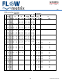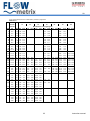
1
09 USER’S GUIDE Installation & Operation Instructions SAFSONIC PORTABLE DOPPLER FLOW METER – PDFM3L Safmag House 498 Sydney Road Congella, Durban South Africa P.O.Box 17143 Congella South Africa, 4013 Reg. No. CK 1986/11597/23 Int Tel.: +27(0)312060630 SA Tel.: 086 110 6028 [email protected] www.flowmetrix.co.za 09 INDEX Introduction 1 Sensor Mounting 1 Surface Preparation 2 Keypad System and Battery 3 Menu System 4 Error Warning Messages 5 Troubleshooting Guide 6 Features and Specifications 7 Flow Rate Guide 8 Questions and Answers 9 Data Logger 10 Logger Setup 15 Logger Data 19 File Saving 21 ASA Pipe Schedules 22 Warranty 24 20/08/2013 4:45 PM 09 Introduction The Safsonic Portable Doppler Flow Meter measures the velocity of liquids in pipelines using a totally non-intrusive principle. The Portable Doppler Flow Meter utilises a high speed, 16-bit microprocessor unit with 32-Kbyte FLASH memory. The user-friendly flowmeter comes with a range of features to ensure easy and reliable flow measurement. The flow signal from the flow sensor is continuously analysed and should the signal quality become unacceptable an error message is displayed. It is designed for use with sewage, waste water, pulp stock, mining slurries, food products and other fluids which contain in excess of 0,1% suspended solids or bubbles. The particle size for successful operation must be greater than 100 microns. Sensor mounting Location Select a location for mounting the sensor at a point where the flow profile is fully developed. Generally the principle of 10 pipe diameters of straight pipe upstream, and 5 pipe diameters downstream will suffice, but should valves or bends exist upstream of the sensor, the amount of straight pipe immediately upstream will need to be increased. Ensure that the sensor is mounted as far as possible from potential noise sources, such as pumps, control valves etc. and mount the sensor at approximately 3/9 o’clock on the pipe (if horizontal) to avoid errors due to air pockets on top, or sediment at the bottom of the pipe. Either vertical or horizontal pipe runs are acceptable for sensor mounting . 1 Instruction Manual 09 Surface preparation Before attaching the transducer head to the pipe surface, an area slightly larger than the flat surface of the transducer must be cleaned to bare metal. (A small amount of pipe pitting, even with spots of paint or rust, will not cause problems). SIDE VIEW - 3 O’CLOCK POSITION ON PIPE IF HORIZONTAL Orientation The transducer must be mounted accurately, parallel to the pipe axis for correct performance, and transducer to pipe contact should be along the centre line of the transducer head. Application of silicon grease coupling to the sensor GOOD Ultrasonic Bonding The sensor must not have any air gap between it and the pipe. Bonding to the pipe is achieved with silicone grease coupling compound. Be sure to fill in any air gaps that may remain at the pipe/transducer interface with additional compound. A pipe clamp kit is included with the flow meter. It includes silicone coupling compound, a Neoprene rubber pad, and straps for pipe diameters up to 600 mm. In applications with excessive vibration it is recommended that the Neoprene rubber pad is inserted between the pipe and the transducer. Coupling compound must be applied to both sides of the pad. Steel band strapping tools and steel strapping for installation of sensors provide excellent sensor strap tension, however care should be taken not to damage sensor with excessive force. 2 Instruction manual 09 Keypad System Pressing the ON/OFF button turns the flowmeter ON and OFF. The Portable Doppler Flow Meter has an easy to use 4-button programming system. The MENU button is used to scroll through the menu structure. The SAVE button is used to save entered changes to the flowmeter programme. The ► and ▲ buttons are used to change numbers and scroll through options. Battery Recharging and battery care The Portable Doppler Flow Meter is supplied with 4 x 1.2V 1000mAh AA size Ni-MH removable cells and a 100-240Vac battery charger. Charge battery fully before first use and thereafter recharge only when fully discharged. The Safsonic Portable Doppler Flow Meter will indicate an error message when battery charge is low and automatically switch off. The Portable Doppler Flow Meter has a constant current circuit controlling the charge current to 150mA. CURRENT 150mA CHARGE TIME 8 hrs The Safsonic Portable Doppler Flow Meter should be switched off during charging. THE CELLS MUST NOT BE OVER CHARGED. Under charging of the cells will reduce the life and capacity of the cells. Low power consumption The Safsonic Portable Doppler Flow Meter is designed for low power consumption allowing over 10 hours operation before re-charging the battery. The Safsonic Portable Doppler Flow Meter features a Low Battery warning with automatic power down. Storage If the Safsonic Portable Doppler Flow Meter is to be stored for an extended time period the cells should be removed. 3 Instruction manual 09 Menu System (Version 1.00) The Safsonic Portable Doppler Flow Meter menu system is easy to use and designed for programming simplicity. With the Safsonic Portable Doppler Flow Meter powered up the instrument will test the suitability of the flow signal. If the signal is suitable the flow total and flow rate are displayed, if not an error message is displayed. 00000000 lt 3.9768 l/s START PROGRAMMING - Press “MENU” Units Mn_1 units? Metric Metric and English units of rate and total measurement are available. Press ▲ until desired value is displayed and MENU to continue. Pipe ID Mn_2 Pipe ID mm 53.4 The precise dimension of the pipe internal diameter (ID) at the point of measurement must be entered. Use the ► button to locate the curser below the number to be changed and press the ▲ button until the desired value is displayed and then press MENU to continue. Rate units Mn_3 rate units? l/s Press ▲ until desired unit is displayed and MENU to continue. Total units Mn_4 tot units? lt Press ▲ until desired unit is displayed and MENU to continue. Clear total? Mn_5 clr total? save total The total can either be cleared or saved. Press ▲ to either save or clear the total and MENU to continue. 4 Instruction manual 09 Damping Mn_6 damping? Medium The level of damping can be selected. Press ▲ until desired unit is displayed and MENU to continue. Cut-off Mn_7 % cutoff 2% The level of cut-off can be entered. Press the ▲ button until the desired value is displayed and MENU to continue. Pulse width Mn_8 puls_width 10-200ms The Safsonic PDFM3 supplies an OCT pulse to the optional logger for every unit of volumetric total eg m3. The pulse width is varied here. The standard is 20ms. The OCT frequency is limited to 100hz, select totaliser units accordingly. Save data Mn_9 save data? Press SAVE Press SAVE to accept all changes made. Error/Warning Messages ERROR MESSAGE ERROR POSSIBLE SOLUTION poor signal Poor signal Increase flow rate Flow rate less than minimum flow rate of 0.3m/s Locate sensor on smaller pipe section No signal Establish flow No flow Inject air into line no signal Particle size and or concentration out of spec charge battery Battery low Charge battery total error counts > 100/s Totaliser count-rate too high Select more suitable total units rate overflow Rate > 999 999 Select more suitable rate units 5 Instruction manual 09 Troubleshooting guide PROBLEM POSSIBLE SOLUTION Meter reading lower than expected Source particles velocity not indicative of average velocity Incorrect mounting of flow sensor Programming error Flow rate lower than expected Insufficient particle size or concentration Relocate sensor to a position where source particles are expected to be moving at the average velocity Remount sensor correctly Review all programmed entries Investigate possible causes and confirm flow rate independently Locate sensor at position where acceptable particle size or concentration is expected. Inject air into the line Meter reading when there is no flow Local ultrasonic noise source Induced signals into sensor cables, e.g. mains voltage 50hz/60hz frequencies Relocate sensor or remove noise source Relocate sensor and or cable away from mains cables or remove noise source Locate sensor at position where acceptable particle size or concentration is expected. Inject air into the line Remount sensor to pipe correctly “Poor signal” displayed when flow exists Insufficient particle size or concentration Sensor coupling to pipe poor Meter reading higher than expected Programming error Flow rate higher than expected Particle velocity at sensor not indicative of average velocity Incorrect mounting of flow sensor Local electrical noise Review all programmed entries Investigate possible causes and confirm flow rate independently Relocate sensor to a position where source particles are expected to be moving at the average velocity Remount sensor correctly Relocate sensor Meter reading erratic Particle velocity at sensor not indicative of average velocity and erratic 6 Relocate sensor to a position where the velocity profile is expected to be suitable Instruction manual 09 Features & Specifications Velocity Range Liquids Pipes Accuracy Repeatability Indication Units Power Supply Battery Charger Carry Case Programming Response Time Electronics enclosure Transducer Temperature limits Cable length Shipping Model No. Standards Calibration 0.25 to 10m/s (0.82 to 30.5ft/s) Containing 0.01% solids >100micron 25-3000mm (1”-120”) Most pipe materials ±2% of Rate for velocities >0.5m/s (1.6ft/s) 2% Rate and Total (password resettable) 2 - Line 16 Character backlit LCD Rate units: m/s, l/s, l/m, l/hr, m3/s, m3/m, m3/hr, ft/s, ft3/s, ft3/m, ft3/hr, USgps, USgpm, USgph, USmgd Total units: l, m 3, Ml, ft3, 103ft3, 106ft3, USG, 103USG, 106USG 4 x AA NICD 1000mA Included 100-240VAC 50/60Hz Included Plugs Available UK, US, EU, AUS Holds meter and all accessories included. 4 Key external keypad 3 Selectable levels of damping Black moulded ABS IP40 (NEMA1) 100 x 196 x 40mm HxWxD (4” x 8” x 1.6”) IP68 (NEMA 6P) Aluminium epoxy-faced 21 x 80 x 28mm HxWxD (0.8” x 3” x 1.1”) Sensor -20 to 90ºC (-4 to 194ºF) Electronics -10 to 50ºC (14 to 122ºF) 3m (9ft) 36 x 20 x 13cm (15” x 10” x 5.2”), 1.4kg (4lbs) PDFM3L CE Certified Certificate with each flow meter 7 Instruction manual 09 FLOW RATE GUIDE PIPE SIZE (mm) 25 40 50 65 80 100 125 150 200 250 300 350 400 450 500 600 700 750 800 PIPE SIZE (INCH) 1 1.6 2 2.6 3.2 4 5 6 8 10 12 14 16 18 20 24 28 30 32 FLOWRATE @ (l/s) m3/hr 0.5 1.8 1.25 4.5 2 7.2 3.3 11.9 5 18.0 8 28.8 12 43.2 18 64.8 31 111.6 49 176.4 70 252.0 96 345.6 125 450.0 159 572.4 196 705.6 283 1018.8 385 1386.0 442 1591.2 500 1800.0 1m/s (3ft/s ) ft3/s gal(US)/s 0.02 0.13 0.04 0.33 0.07 0.53 0.12 0.87 0.18 1.32 0.28 2.11 0.42 3.17 0.64 4.75 1.09 8.19 1.73 12.9 2.47 18.5 3.39 25.4 4.41 33.0 5.62 42.0 6.92 51.8 9.99 74.7 13.60 101.7 15.61 116.7 17.66 132.1 8 (l/s) 5 12.5 20 33 50 80 120 180 310 490 700 960 1250 1590 1960 2830 3850 4420 5000 FLOWRATE @ 10m/s (30ft/s) m3/hr ft3/s gal(US)/s 18 0.18 1.32 45 0.44 3.30 72 0.71 5.28 118.8 1.17 8.72 180 1.77 13.2 288 2.83 21.1 432 4.24 31.7 648 6.36 47.5 1116 10.95 81.9 1764 17.30 129.4 2520 24.72 184.9 3456 33.90 253.5 4500 44.14 330.1 5724 56.15 419.9 7056 69.22 517.6 10188 99.94 747.4 13860 135.96 1016.8 15912 156.09 1167.3 18000 176.57 1320.5 Instruction Manual 09 Questions and Answers The pipe vibrates. Will it affect the flow meter? Common vibration frequencies are far lower than the sonic frequencies used by the flow meter, and will not normally affect accuracy or performance. Will pipe corrosion affect accuracy of the flow meter? Yes. Rust, loose paint etc. must be removed from the outside of the pipe to provide a clean mounting area when installing a Doppler sensor. Severe corrosion/oxidation on the inside of the pipe may prevent the ultrasound signal from penetrating into the flow. If the pipe cannot be cleaned, a spool piece should be installed for sensor mounting. What effect do pipe liners have on the flow meter? The air gap between loose insertion liners and the pipe wall prevent the ultrasound signal from entering the flow. Better results can be expected with bonded liners such as rubber, epoxy or tar, however an on site test is recommended to determine if the application is suitable for a Doppler flow meter. Why is Doppler only recommended for liquids containing suspended solids or gases? The Doppler sensor transmits ultrasound into the flow stream, which must be reflected back to the sensor to indicate flow velocity. Gas bubbles or suspended solids act as reflectors for the Doppler signal. As a guideline, Safsonic Doppler flow meters are recommended for liquids containing solids or bubbles with a minimum size of 100 microns and a minimum concentration of 100 ppm. Can the sensor be submerged in water? Yes, for short periods of time or by accident, but not for continuous operation. The sensor is constructed to withstand submersion without damage, but external liquid moving in contact with the sensor can be interpreted as flow and cause false readings. Can I change the length of the sensor cable? No. A 3m cable is supplied with the Safsonic Portable Doppler Flow Meter as standard. Does the direction of flow matter for Sensor mounting? The Doppler flow meter will measure and totalize flow in either direction. A check valve should be used in applications where backflow may occur. 9 Instruction manual 09 Data Logger Introduction The PDFM3L is a Portable Doppler Flow Meter with a standard logging module.The PDFM3L uses a Real Time Clock (RTC) to time stamp the logs and ensure an accurate logging interval. The Logger is a serial device that connects to a standard PC running Windows and the PDFM3L Logging Software. This user manual steps through the use of the Logger Software. Java is required to run the Logger Software. A Java installation file is included on the CD in “java/”. SECTION 2. PDFM3 Logger Software General To perform logs with the PDFM3L the user needs to connect the PC to the PDFM3L via the serial cable and Logger Software and set the time and date, the log interval and clear the internal memory of the logger. To retrieve logs from the PDFM3L the user needs to connect to the PDFM3L via the serial cable and Logger Software and download the logs. Once the logs are downloaded the user needs to save them in a ‘*.csv’ file. Ensure that the batteries are fully charged before setting up the PDFM3L for logs! Do not remove the batteries after the PDFM3L has been set up as the setup data will be lost! 10 Instruction manual 09 The startup screen of the PDFM3L. Connection and Disconnection To connect to the PDFM3L click on the connection button. 11 Instruction manual 09 In the RS232 Settings dialog select the com port that the serial cable is connected to. To connect click on the ‘Connect’ button. 12 Instruction manual 09 To cancel click on the ‘Cancel’ button. Once a connection has been established to the PDFM3L the disconnection button, date/time button, log interval button, download button, clear button and table button become available. To disconnect from the PDFM3L click on the disconnect button 13 Instruction manual 09 When attempting to disconnect from the PDFM3L a confirmation dialog will appear. Click on ‘Yes’ to disconnect or ‘No’ to remain connected. 14 Instruction manual 09 Logger Setup The date and time of the PDFM3L needs to be setup in preparation for logs. Do not setup the date and time before retrieving the logs first. Always setup the date and time before clearing the internal memory in preparation for logging. In the Real Time Clock setup a snapshot of the PC clock and a snapshot of the PDFM3L is presented. If the date and time are the same click the ‘Cancel’ button. 15 Instruction manual 09 If the date and time differ click the ‘Synchronise’ button to update the PDFM3L. The Real Time Clock must be setup correctly for proper Iogging of logs . 16 Instruction Manual 09 The log interval of the PDFM3L needs to be setup in preparation for logs. Do not setup the log interval before retrieving the logs first. Always setup the log interval before clearing the internal memory in preparation for logging. Select the log interval as required. The log interval is the rate at which logs are taken and saved.The setup of the Log Interval can be cancelled . 17 Instruction manual 09 The log interval can be saved to the PDFM3L to complete the setup of the Logging. The Log Interval must be setup correctly for proper Iogging of logs. Changing the log interval will clear the internal memory of the PDFM3L and begin new logs with the current log interval and date/ time. Do this only once the saved logs have been read from the PDFM3L or data loss will occur. 18 Instruction manual 09 Logger Data To download logs that have been taken and saved click on the download button. Do not setup the log interval before retrieving the logs first. Do not setup the date and time before retrieving the logs first. During the download the table will appear and begin filling with the logs. The circle in the corner indicates that the software is still busy retrieving logs. 19 Instruction manual 09 To clear the PDFM3L internal memory for new logs click on the clear logs button. Do not clear the PDFM3L internal memory before saved logs have been retrieved. Clearing the PDFM3L internal memory does not delete the logs that have been downloaded via the software. However save the downloaded logs as soon as possible to prevent data loss. 20 Instruction Manual 09 File Saving To save the downloaded logs to a file click on the save button . A file save dialog will appear. Type in a filename or select an existing file that has already been created by the PDFM3 Logging Software. If the file does not exist it will be created. If the file does exist it will be appended to. DUPLICATE data can be created if it exists in both the existing file and the data logger. 21 Instruction manual 09 ASA steel pipe schedules ANSI B36.19 ANSI B36.10 Schedule Outside 5S 10S 40S/STD diameter 80S/XS STD XS Wall thickness and weight kg/mm DN mm mm kg/m mm kg/m mm kg/m mm 8 10.3 NPS mm 1/8 kg/m 1.24 0.28 1.73 0.37 2.41 0.48 8 13.7 1/4 1.65 0.50 2.24 0.64 3.02 0.81 10 17.2 3/8 1.65 0.64 2.31 0.86 3.20 1.12 15 21.3 1/2 1.65 0.81 2.11 1.01 2.77 1.28 3.73 1.64 20 26.7 3/4 1.65 1.03 2.11 1.3 2.87 1.71 3.91 2.23 25 33.4 1 1.65 1.31 2.77 2.12 3.38 2.54 4.55 3.28 32 42.2 1 1/4 1.65 1.67 2.77 2.73 3.56 3.44 4.85 4.53 40 48.3 1 1/2 1.65 50 60.3 65 73.0 80 88.9 100 101.6 100 114.3 4 125 141.3 150 168.3 200 250 kg/m mm kg/m 1.92 2.77 3.15 3.68 4.11 5.08 5.49 1.65 2.42 2.77 3.99 3.91 5.51 5.54 7.59 2 1/2 2.11 3.74 3.05 5.34 5.16 8.75 7.01 11.6 2.11 4.58 3.05 6.55 5.49 11.5 7.62 15.5 3 1/2 2.11 5.25 3.05 7.52 5.74 13.8 8.08 18.9 2.11 5.92 3.05 8.49 6.02 16.3 8.56 22.6 5 2.77 9.60 3.40 11.7 6.55 22.1 9.53 31.4 6 2.77 11.5 3.40 14.0 7.11 28.7 10.97 43.2 219.1 8 2.77 15.0 3.76 20.2 8.18 43.1 12.70 65.6 273.0 10 3.4 22.9 4.19 28.2 9.27 61.1 12.70 82.7 300 323.9 12 3.96 31.7 4.57 36.5 9.53 74.9 12.70 98.8 350 355.6 14 3.96 34.8 4.78 41.9 9.53 82.5 12.70 109 400 406.4 16 4.19 42.1 4.78 48.0 9.53 94.6 12.70 125 450 457 18 4.19 47.4 4.78 54.1 9.53 107 12.70 141 500 508 20 4.78 60.2 5.54 69.6 9.53 119 12.70 157 559 22 4.78 66.2 5.54 76.7 9.53 131 12.70 173 610 24 5.54 83.7 6.35 95.9 9.53 143 12.70 190 660 26 9.53 155 12.70 206 711 28 9.53 167 12.70 222 762 30 9.53 179 12.70 238 813 32 9.53 191 12.70 254 864 34 9.53 204 12.70 270 914 36 9.53 216 12.70 286 965 38 9.53 228 12.70 303 1016 40 9.53 240 12.70 319 1067 42 9.53 252 12.70 335 1118 44 9.53 264 12.70 351 1168 46 9.53 276 12.70 367 1219 48 9.53 288 12.70 383 1321 52 9.53 313 12.70 417 1422 56 9.53 339 12.70 449 1524 60 9.53 362 12.70 482 1626 64 9.53 387 12.70 514 600 700 800 900 1000 2 3 6.35 120 7.92 149 The table shows the ANSI B36.19 and a part of the B36.10 standard; 22 Instruction manual 09 some of these dimensions are outside AST's production programme. ANSI B36.10 Schedule Outside 10 20 diameter 30 40 60 80 120 Wall thickness and weight kg/mm DN mm mm kg/m mm kg/m mm kg/m 8 10.3 NPS mm kg/m 1/8 1.24 0.28 mm kg/m mm kg/m 1.73 0.37 2.41 0.48 8 13.7 1/4 1.65 0.50 2.24 0.64 3.02 0.81 10 17.2 3/8 1.65 0.64 2.31 0.86 3.20 1.12 15 21.3 1/2 2.11 1.01 2.77 1.28 3.73 1.64 20 26.7 3/4 2.11 1.30 2.87 1.71 3.91 2.23 25 33.4 1 2.77 2.12 3.38 2.54 4.55 3.28 32 42.2 1 1/4 2.77 2.73 3.56 3.44 4.85 4.53 40 48.3 1 1/2 2.77 3.15 3.68 4.11 5.08 5.49 50 60.3 2.77 3.99 3.91 5.51 5.54 7.59 65 73.0 2 1/2 3.05 5.34 5.16 8.75 7.01 11.6 3.05 6.55 5.49 11.5 7.62 15.5 3 1/2 3.05 7.52 5.74 13.8 8.08 18.9 2 80 88.9 100 101.6 100 114.3 4 3.05 8.49 6.02 16.3 8.56 22.6 11.13 28.7 125 141.3 5 3.40 11.7 6.55 22.1 9.53 31.4 12.70 40.8 150 168.3 6 3.40 14.0 7.11 28.7 10.97 43.2 14.27 55.0 200 219.1 8 3.76 20.2 6.35 33.8 8.18 43.1 10.31 53.8 12.70 65.6 18.26 91.7 250 273.0 10 4.19 28.2 6.35 42.3 7.8 51.7 9.27 61.1 12.70 82.7 15.09 97.3 21.44 135 300 323.9 12 4.57 36.5 6.35 50.4 8.38 66.1 10.31 80.9 14.27 110 17.48 134 25.40 190 350 355.6 14 6.35 55.5 7.92 68.9 9.53 82.5 11.13 95.9 15.09 128 19.05 160 27.79 228 400 406.4 16 6.35 63.5 7.92 78.9 9.53 94.6 12.7 125 16.66 162 21.44 206 30.96 291 450 457 18 6.35 71.6 7.92 88.9 11.13 124 14.27 158 19.05 209 23.83 258 34.93 369 500 508 20 6.35 79.7 9.53 119 12.70 157 15.09 186 20.62 251 26.19 316 38.10 448 559 22 6.35 87.8 9.53 131 12.70 173 22.23 298 28.58 379 41.28 534 610 24 6.35 95.9 9.53 143 14.27 213 24.61 360 30.96 448 46.02 649 660 26 7.92 129 12.70 206 711 28 7.92 139 12.70 222 15.88 276 762 30 7.92 149 12.70 238 15.88 296 813 32 7.92 159 12.70 254 15.88 864 34 7.92 170 12.70 270 15.88 914 36 7.92 179 12.70 286 965 38 9.53 228 12.70 1016 40 9.53 240 1067 42 9.53 252 1118 44 9.53 1168 46 1219 600 700 800 900 1000 3 mm kg/m 17.48 259 317 17.48 348 337 17.48 370 15.88 357 19.05 426 302 15.88 377 12.70 319 15.88 397 12.70 335 15.88 417 264 12.70 351 15.88 438 9.53 276 12.70 367 15.88 458 48 9.53 288 12.70 383 15.88 478 1321 52 9.53 313 12.70 416 15.88 518 1422 56 9.53 337 12.70 448 15.88 558 1524 60 9.53 361 12.70 480 15.88 599 1626 64 9.53 385 12.70 512 15.88 639 23 Instruction manual 09 Warranty Flowmetrix SA CC warrants to the purchaser that the equipment to be delivered hereunder will be free from defects in materials, workmanship and title and will be of the kind and quality designated in the proposal. The foregoing warranty is exclusive and in lieu of all other warranties whether express or implied including any warranty of merchantability or of fitness for a particular purpose. Warranties other than the above will only be effective if written and signed by an officer of Flowmetrix SA CC If within 1 (one) year from the date of delivery, the equipment delivered hereunder does not meet the warranties specified above, Flowmetrix SA CC shall thereupon correct such defects, at its sole discretion, either by repairing or by replacing the instrument in its entirety. The costs of returning the equipment to Flowmetrix SA CC and for the repaired or replaced item being returned to the purchaser shall be for the account of the purchaser. The liability of Flowmetrix SA CC is conditioned upon the equipment covered hereunder being handled, installed, operated, maintained, stored or used, as the case may be, in strict accordance with the written instructions or technical direction supplied by Flowmetrix SA CC, and is further conditioned upon the purchasers prompt written notice (within 30 days) to Flowmetrix SA CC of such defects. Flowmetrix SA CC makes no warranties which extend to the items covered hereby due to improper handling, installation, operation, maintenance, storage or use; abnormal or undisclosed environmental conditions; or operating or use in an otherwise improper manner. The liability of Flowmetrix SA CC to the purchaser, except as to title, arising out of the supplying of the equipment or its use, under this warranty article, shall not, in any case, exceed the cost of correcting defects in the equipment as herein provided and upon the expiration of the warranty described herein, all such warranty liability shall terminate. The foregoing shall constitute sole warranty remedy of the purchaser and the sole warranty liability of Flowmetrix SA CC. Goods Return Procedure Damaged or defective equipment should be returned to the supplier prepaid. Do not return goods until written authorisation to do so has been obtained. Returned goods must have accompanying them a letter stating the following: Your company name and order number The contact person at your company Serial number and name of product Description of damage and cause if known Nature of any repair attempted by the user Type of repair, replacement or adjustment requested 24 Instruction manual