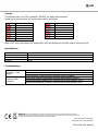
1
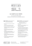
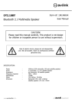
FC4 Item ref: 154.001UK Desktop / Foot Controller Caution: Please read this manual carefully before operating Damage caused by misuse is not covered by the warranty Introduction Thank you for choosing the FC4 controller for your effect lighting setup. This desktop or floor mounted controller is specifically designed to operate QTX SmartLIGHT RGBW and RGBWAV fixtures. Please read this manual to achieve the best results from your product. Unpacking Your FC4 controller should reach you in good condition, supplied with an RJ45 connection lead. If there is any damage or items missing from the packaging, contact your dealer immediately. Warning To prevent risk of fire or electric shock, do not expose electrical parts to rain or moisture. If any liquids are spilled on the housing, allow it to dry out and have checked by qualified personnel. Avoid any impact, dropping or extreme pressure to the housing. No user serviceable parts inside - do not open the case. Refer all servicing to qualified service personnel. Placement The FC4 can be used on the floor as a foot controller or on a desktop, pressing the pads by hand Ensure that the FC4 is positioned on a flat stable surface with adequate clearance for the RJ45 cable Cleaning Use a soft dry or slightly damp to clean the housing Do not use solvents Setting up The FC4 is powered directly from the RJ45 connector of a QTX SmartLIGHT unit. This lead (supplied with the FC4) also carries the control signal back to the SmartLIGHT unit. Up to 32 units can be controlled together from the FC4. After connecting the first SmartLIGHT fixture to the FC4, connect XLR leads from the DMX OUT connector to the DMX IN of the next fixture and then from DMX OUT to DMX IN of the third fixture and so on to connect all SmartLIGHT units in a chain, as shown below. For SL-H7 and SL-H12 six-colour units, set the DMX address on each fixture to “A001” For SL-36, SL-64, SL-Q8 and SL-Q12 quad colour units, set the DMX address on each fixture to “A011” This will ensure that the correct RGBW or RGBWAV instructions are sent to the appropriate fixtures. 154.001UK User Manual Operation The FC4 controller features a minimalist design for ease of use. Once connected to the first SmartLIGHT in line and with the SmartLIGHT powered up, the FC4 should remember the previous selection. If there is no light output, the last selection may have been “BLACKOUT” Press the “BLACKOUT” pad and the fixture(s) will light to the last setting. The LED display on the FC4 will show the current control status. Whilst in BLACKOUT mode, pressing either of the other 2 pads will cause the display to flash with a new mode or colour setting. When BLACKOUT is pressed, the light control will resume to this new selection. Modes The centre pad is labelled “MODE” for accessing internal programs. Repeated pressing of this pad will cycle through the modes, as follows. Auto modes Colour Colour Colour Colour jump cycling through 15 colours scroll through deep colours scroll through pastel colours fade in / fade out Sound activated modes Sound Sound Sound Sound activated activated activated activated colour jump every beat colour jump alternate beats white strobe pulse with fade out For sound activated modes, there is an internal microphone at the rear of the FC4, which can be adjusted using a screwdriver to turn the “SOUND SENSITIVITY” control between MIN and MAX sensitivity. 154.001UK User Manual Colours The leftmost pad on the FC4 is labelled “COLOUR” for static colour selection. Pressing this pad will select one of 15 preset colours, as follows. Red Green Blue White Amber Violet Yellow Magenta Warm White Orange Pink Emerald Aqua Peach Cool White When not in use, power down the SmartLIGHT units and disconnect the RJ45 cable if storing the FC4. Specifications Connection Controls Dimensions Weight 8P8C modular plug (RJ45) Colour, Mode, Blackout, Sound Sens. 230 x 175 x 45mm 950g Troubleshooting No power / light output Incorrect DMX behaviour Check connection to a compatible QTX SmartLIGHT unit using the RJ45 cable Ensure that the SmartLIGHT unit is powered up Press BLACKOUT pad to check if blackout mode is enabled Check RJ45 lead and connectors and XLR leads between fixtures Ensure that RGBW (quad colour) units are set to DMX address “A011” Ensure that RGBWAV (6-colour) units are set to DMX address “A001” Disposal: The “Crossed Wheelie Bin” symbol on the product means that the product is classed as Electrical or Electronic equipment and should not be disposed with other household or commercial waste at the end of its useful life. The goods must be disposed of according to your local council guidelines. Errors and omissions excepted. Copyright© 2015. AVSL Group Ltd 154.001UK User Manual