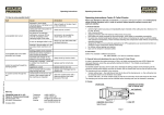
1
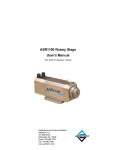
ASR1200 Rotary Stage
User’s Manual
P/N: EDS132 (Revision 1.03.00)
Dedicated to the Science of Motion
Aerotech, Inc.
101 Zeta Drive,
Pittsburgh, PA, 15238
Phone: 412-963-7470
Fax: 412-963-7459
www.aerotech.com
Product Registration
Register online at: http://www.aerotech.com/prodreg.cfm
Technical Support
United States Headquarters:
Phone: (412) 967-6440
Fax: (412) 967-6870
Email: [email protected]
United Kingdom:
Phone: +44 118 940 9400
Fax: +44 118 940 9401
Email: [email protected]
Germany:
Phone: +49 911 967 9370
Fax: +49 911 967 93720
Email: [email protected]
Japan:
Phone: +81(0)47-489-1741 (Sales)
Phone: +81(0)47-489-1742 (Service)
Fax: +81(0)47-489-1743
Email: [email protected]
China:
Phone: +852-3793-3488
Email: [email protected]
Revision History
Revision 1.03.00
February 21, 2011
Revision 1.02.00
August 16, 2010
Revision 1.01.00
December 2, 2008
Revision 1.00.00
October 14, 2008
Product names mentioned herein are used for identification purposes only and may be trademarks of
their respective companies.
© Aerotech, Inc. 2011
ASR1200 Rotary Stage User's Manual
Table of Contents
Table of Contents
Table of Contents
List of Figures
List of Tables
iii
v
vii
Chapter 1: Overview
1
1.1. Standard Features
1.1.1. Rotary Axis
1.1.2. Wet Cut
1.2. Optional Features
1.2.1. Mounting Plate
1.2.2. Wrenches
1.2.3. Electronics Controller
1.2.4. Ringseals
1.3. Model Numbers
1.4. Dimensions
1.5. Safety Procedures and Warnings
1.6. EC Declaration of Incorporation
Chapter 2: Installation
2.1. Unpacking and Handling the Stage
2.2. Preparing the Mounting Surface
2.3. Securing the Stage to the Mounting Surface
2.4. Attaching the Payload to the Stage
2.5. Changing ASR Workholding Devices
2.5.1. Collet Installation and Removal Procedure
2.6. Electrical Installation
2.7. Air Requirements
2.8. Wet Cut Fluid Requirements
2
2
2
3
3
3
3
3
4
5
6
8
9
9
10
11
12
13
13
16
16
16
Chapter 3: Operating Specifications
17
3.1. Environmental Specifications
3.2. Accuracy and Temperature Effects
3.3. Basic Specifications
3.4. Load Capability
17
17
18
20
Chapter 4: Maintenance
4.1. Service and Inspection Schedule
4.2. Cleaning and Lubrication
4.2.1. Collet & Collet Chuck Lubrication and Cleaning
4.3. Seal Replacement
4.3.1. Piston Seal Change Procedure
4.3.2. Ringseal O-Ring Replacement
4.3.3. Wet Cut Rotary Union Seal Replacement
4.4. Wet Cut Rotary Union Removal
21
21
22
22
23
23
23
25
29
Appendix A: Warranty and Field Service
31
Appendix B: Technical Changes
33
Index
35
Reader's Comments
37
www.aerotech.com
iii
Table of Contents
iv
ASR1200 Rotary Stage User's Manual
www.aerotech.com
ASR1200 Rotary Stage User's Manual
List Of Figures
List of Figures
Figure 1-1:
Figure 1-2:
Figure 2-1:
Figure 2-2:
Figure 2-3:
Figure 2-4:
Figure 3-1:
Figure 4-1:
Figure 4-2:
Figure 4-3:
Figure 4-4:
Figure 4-5:
Figure 4-6:
Figure 4-7:
Figure 4-8:
Figure 4-9:
Figure 4-10:
ASR1200 Rotary Stage
ASR1200 Dimensions
ASR1200 Stage Showing Mounting Plate (Top View)
ASR1200 Stage Without Mounting Plate (Bottom View)
Installation of Collet into Collet Nut
Installation Procedure for Collet/Collet Nut
ASR1200 Wet Cut Rotary Union Location
Ringseal Removal and Replacement
Typical Ringseal
Cross-Section View of Ringseal Showing O-Ring
Cross-Section View of Wet Cut Rotary Union Assembly
Rotary Union Hardware Removal
Seal Installation
Seal Retainer Assembly
Wet Cut Rotary Union Shaft Inspection
Wet Cut Rotary Union
Wet Cut Rotary Union Installation
www.aerotech.com
1
5
11
11
14
15
20
23
24
24
25
26
26
27
27
29
30
v
List of Figures
vi
ASR1200 Rotary Stage User's Manual
www.aerotech.com
ASR1200 Rotary Stage User's Manual
List of Tables
List of Tables
Table 1-1:
Table 3-1:
Table 3-2:
Table 3-3:
Table 4-1:
Table B-1:
Table B-2:
Model Numbering System
Environmental Specifications
ASR1200 Series Specifications
ASR1200 Motor Specifications
Recommended Lubricants
Current Changes (1.03.00)
Archived Changes
www.aerotech.com
4
17
18
19
22
33
34
vii
List of Tables
viii
ASR1200 Rotary Stage User's Manual
www.aerotech.com
ASR1200 Rotary Stage User's Manual
Overview
Chapter 1: Overview
Aerotech’s ASR1200 mechanical-bearing rotary stage is a system that combines high precision rotary positioning with an integrated pneumatically controlled collet chuck for material handling. The ASR1200 series utilizes direct-drive brushless motor technology to maximize positioning performance and virtually eliminate the
need for maintenance. The stage is also equipped with a rotary union attachment for wet cutting operations.
These features make the ASR1200 an ideal choice for applications where low maintenance, high throughput,
and low total cost of ownership are essential.
The ASR1200 has been designed with a collet chuck that can support ER16 collets (manufactured to
DIN6499 specs) to allow for a wide range of materials and applications. This product is intended for light
industrial manufacturing or laboratory use.
This chapter introduces standard and optional features of the ASR1200, explains the model numbering system, and gives general safety precautions. Figure 1-1 shows a typical ASR1200.
Figure 1-1:
ASR1200 Rotary Stage
N O T E : Aerotech continually improves its product offerings, and listed options may be superseded at any
time. Refer to the most recent edition of the Aerotech Motion Control Product Guide for the most current
product information at www.aerotech.com.
N O T E : This manual should be read in its entirety before operating the ASR1200 system.
Failure to follow the maintenance procedures outlined in Section 4.3.3. will result in voiding of
warranty.
www.aerotech.com
Chapter 1
1
Overview
ASR1200 Rotary Stage User's Manual
1.1. Standard Features
1.1.1. Rotary Axis
ASR1200 stages come standard with a direct drive brushless motor with a non-contacting integral rotary
union. These features combine to create a low friction, low maintenance rotary stage capable of high accelerations and low positioning error. With a non-contact rotary union, there are no seals to be replaced or lubricated allowing for a lifetime of maintenance free performance. The brushless, slotless motor design allows
for extremely high torque coupled with smooth motion. There are no brushes to wear, no belts to tension, and
no gears to wear resulting in a completely maintenance-free motor.
The ASR1200 is designed with an ER16 style collet chuck. The maximum tube diameter supported by the
ER16 collet chuck is 5.8 mm. The collet is retained with a threaded collet nut enabling quick changeover. It
is configured in a “fail-safe” normally-closed mode where full clamping force is applied when no air pressure
is present.
N O T E : Aerotech recommends using electro-polished collets manufactured to DIN6499 specs.
1.1.2. Wet Cut
The ASR1200 rotary stage has a standard wet cut rotary union that is used for fluid delivery (@ 100 psi max
pressure) in wet laser cutting applications. A 1/4" NPT tapped hole is supplied on the rear of the rotary to
allow for connections of different length pressure vessels depending on the tube length being cut. See Section 3.4. , Section 4.3.3. , and Section 4.4. for details regarding use and maintenance of the wet cut rotary
union.
N O T E : The purchase of a ringseal will also be required based on the tube diameter used in the cutting
application. Consult Aerotech for more information.
2
Chapter 1
www.aerotech.com
ASR1200 Rotary Stage User's Manual
Overview
1.2. Optional Features
1.2.1. Mounting Plate
ASR1200 stages can be configured to include a mounting plate that can use either M6 or 1/4-20 bolts. The bottom of this mounting plate is precision machined and verified for flatness. If the mounting plate is not
selected, a custom mounting option can be attached using the (Qty-4) M6 tapped holes in the bottom of the
stage.
1.2.2. Wrenches
This option is selected when spanner wrenches for removing the collet nut are desired.
1.2.3. Electronics Controller
The ASR1200 stage is part of a complete Aerotech motion control system, which is adjusted at the factory
for optimum performance. Setup involves connecting a stage to the appropriate drives with the cables provided. Refer to your electrical documentation package for further information.
1.2.4. Ringseals
Replaceable O-Ring seals are required to perform wet cut operations using the ASR1200. These ringseals
are sized for specific tube diameters in sizes up to 5.8 mm. Consult Aerotech for supported sizes.
www.aerotech.com
Chapter 1
3
Overview
ASR1200 Rotary Stage User's Manual
1.3. Model Numbers
The stage model number indicates the optional features on a particular stage. To determine the options on
your stage, refer to Table 1-1 for an explanation of the numbering system.
Example: ASR1200-10-HPD-NC-RE2048AS-MP-WRENCH-RINGSEAL-1.08MM
Table 1-1:
Model Numbering System
ASR1200, Direct Drive Rotary Stage
ASR1200
Direct drive rotary stage with integral ER-style collet chuck
Drive Motor
-10
5 N-m peak, 1.95 N-m continuous direct-drive brushless motor
Connector
-HPD
High power D connector for motor power and 25-pin D for feedback
-25D
Dual 25-pin D connectors with bridged pins for motor power
-MS
MS-style connectors for motor power and feedback
Collet Chuck
-NC
Normally Closed Collet Chuck for ER16 Collet
Position Transducer
-RE2048AS
Incremental encoder with 2048 cycles per rev sinusoidal output signal
-RE5000AS
Incremental encoder with 5000 cycles per rev sinusoidal output signal
Rear Seal
-S
Rear shaft seal
-NS
No shaft seal
Options
4
-MP
Mounting plate
-WRENCH
Spanner wrenches for changing ER16 collets
-RINGSEAL
O-ring seal assembly for wet cutting. Consult factory for supported sizes.
Chapter 1
www.aerotech.com
ASR1200 Rotary Stage User's Manual
Overview
1.4. Dimensions
Figure 1-2:
www.aerotech.com
ASR1200 Dimensions
Chapter 1
5
Overview
ASR1200 Rotary Stage User's Manual
1.5. Safety Procedures and Warnings
The following statements apply throughout this manual. Failure to observe these precautions could result in
serious injury to those performing the procedures and damage to the equipment.
This manual and any additional instructions included with the stage should be retained for the lifetime of the
stage.
To minimize the possibility of electrical shock and bodily injury or death, disconnect all electrical power prior to making any electrical connections.
To minimize the possibility of electrical shock and bodily injury or death when any electrical
circuit is in use, ensure that no person comes in contact with the circuitry when the stage is
connected to a power source.
To minimize the possibility of bodily injury or death, disconnect all electrical power prior to
making any mechanical adjustments.
Moving parts of the stage can cause crushing or shearing injuries. All personnel must
remain clear of any moving parts.
Improper use of the stage can cause damage, shock, injury, or death. Read and understand
this manual before operating the stage.
If the stage is used in a manner not specified by the manufacturer, the protection provided
by the stage can be impaired.
Stage cables can pose a tripping hazard. Securely mount and position all stage cables to
avoid potential hazards.
6
Chapter 1
www.aerotech.com
ASR1200 Rotary Stage User's Manual
Overview
Do not expose the stage to environments or conditions outside the specified range of operating environments. Operation in conditions other than those specified can cause damage to
the equipment.
The stage must be mounted securely. Improper mounting can result in injury and damage to
the equipment.
Use care when moving the stage. Manually lifting or transporting stages can result in injury.
Only trained personnel should operate, inspect, and maintain the stage.
This stage is intended for light industrial manufacturing or laboratory use. Use of the stage
for unintended applications can result in injury and damage to the equipment.
Before using this stage, perform an operator risk assessment to determine the needed
safety requirements.
www.aerotech.com
Chapter 1
7
Overview
ASR1200 Rotary Stage User's Manual
1.6. EC Declaration of Incorporation
Manufactorer:
Aerotech, Inc.
101 Zeta Drive
Pittsburgh, PA 15238
USA
herewith declares that the product:
Aerotech, Inc. ASR1200 Stage
is intended to be incorporated into machinery to constitute machinery covered by the Directive
2006/42/EC as amended;
does therefore not in every respect comply with the provisions of this directive;
and that the following harmonized European standards have been applied:
EN ISO 12100-1,-2:2003+A1:2009
Safety of machinery - Basic concepts, general principles for design
ISO 14121-1:2007
Safety of machinery - Risk assessment - Par 1: Principles
EN 60204-1:2005
Safety of machinery - Electrical equipment of machines - Part 1: General requirements
and further more declares that
it is not allowed to put the equipment into service until the machinery into which it
is to be incorporated or of which it is to be a component has been found and
declared to be in conformity with the provisions of the Directive 2006/42/EC and
with national implementing legislation, i.e. as a whole, including the equipment
referred to in this Declaration.
Authorized Representative:
Address:
Manfred Besold
AEROTECH GmbH
Süd-West-Park 90
D-90449 Nürnberg
Name:
Position:
Location:
Date:
8
Alex Weibel /
Engineer Verifying Compliance
Pittsburgh, PA
February 21, 2011
Chapter 1
www.aerotech.com
ASR1200 Rotary Stage User's Manual
Installation
Chapter 2: Installation
This chapter describes the installation procedure for the ASR1200 stage, including handling the stage properly, preparing the mounting surface to accept the stage, securing the stage to the mounting surface, attaching the payload, and making the electrical connections.
Installation must follow the instructions in this chapter. Failure to follow these instructions
could result in injury and damage to the equipment.
2.1. Unpacking and Handling the Stage
Carefully remove the stage from the protective shipping container. Use compressed nitrogen or clean, dry air
to remove any dust or debris that has collected during shipping. If any damage has occurred during shipping,
report it immediately.
Before operating the stage, it is important to let the stage stabilize at room temperature for at least 12 hours.
Allowing the stage to stabilize to room temperature will ensure that all of the alignments, preloads, and tolerances are the same as they were when tested at Aerotech. Set the stage on a smooth, flat, and clean surface.
Each stage has a label listing the system part number and serial number. These numbers contain information
necessary for maintaining or updating system hardware and software. Locate this label and record the information for later reference.
Improper stage handling could adversely affect the stage’s performance. Use care when
moving the stage. Manually lifting or transporting the stage can result in injury
Do not allow the stage to drop onto any surface.
www.aerotech.com
Chapter 2
9
Installation
ASR1200 Rotary Stage User's Manual
2.2. Preparing the Mounting Surface
The mounting surface should be flat and have adequate stiffness in order to achieve the maximum performance from the ASR1200 stage. When a stage is mounted to a non-flat surface, the stage can be distorted as the mounting screws are tightened. This distortion will decrease the overall accuracy of the stage.
Adjustments to the mounting surface must be done before the stage is secured.
N O T E : To maintain accuracy, the mounting surface should be flat within 1 µm per 50 mm.
N O T E : The stage base is precision machined and verified for flatness prior to stage assembly at the factory. If machining is required to achieve the desired flatness, it should be performed on the mounting surface rather than the stage base. Shimming should be avoided if possible. If shimming is required, it should
be minimized to improve the rigidity of the system.
10
Chapter 2
www.aerotech.com
ASR1200 Rotary Stage User's Manual
Installation
2.3. Securing the Stage to the Mounting Surface
If a mounting plate is included on the stage, mount using (Qty-4) M6 or 1/4-20 bolts (refer to Figure 2-1). If the
stage is configured without a mounting plate, use the (Qty-4) M6 tapped holes on the bottom of the stage to
attach an alternative means of mounting (see Figure 2-2).
The stage must be mounted securely. Improper mounting can result in injury and damage to
the equipment.
Figure 2-1:
Figure 2-2:
www.aerotech.com
ASR1200 Stage Showing Mounting Plate (Top View)
ASR1200 Stage Without Mounting Plate (Bottom View)
Chapter 2
11
Installation
ASR1200 Rotary Stage User's Manual
2.4. Attaching the Payload to the Stage
To prevent damage to the stage or parts, test the operation of the stage before any material is held in the collet. Proceed with the electrical installation and test the motion control system.
To operate the collet, clean compressed air or nitrogen must be supplied to the stage (see Section 2.7. ). The
one-touch air inlet fitting accepts 4 mm or 5/32” OD plastic air line.
Once air is supplied, material of the appropriate size can be placed in the collet. All collets supplied by Aerotech are clearly labeled with their clamping size range and collet style. Be sure to use only the correct size
material in the collet. If an incorrect material size is clamped, the accuracy of the collet could be compromised. Never clamp material or tools that are larger than the specified range. It is also important to have
the material or tool inserted at least 2/3 the length of the collet bore. Any less than this could cause permanent deformation of the collet and reduce accuracy (see Section 2.5.1. for collet installation).
12
Chapter 2
www.aerotech.com
ASR1200 Rotary Stage User's Manual
Installation
2.5. Changing ASR Workholding Devices
ASR1200 stages are equipped with an ER16 style collet. It is important that only the collets designed for a
particular collet holder are used. Aerotech collet chucks are designed for use with ER collets manufactured to
DIN6499 specifications. Aerotech recommends the use of ultra precision electroplated collets only. Contact
the factory for more details.
N O T E : Various grip diameters are commonly available and can be interchanged following the collet
removal and installation procedure detailed in Section 2.5.1.
2.5.1. Collet Installation and Removal Procedure
To minimize the possibility of bodily injury, confirm that all electrical power is disconnected
prior to making any mechanical adjustments.
1. Before any collet change operation, remove power to the stage.
2. Apply air pressure to loosen the collet chuck.
3. Unscrew the collet nut. If necessary, use a spanner wrench (available from Aerotech).
4. For installation of a collet, first clean the collet housing, collet nut threads, collet nut, and new collet. Acetone or isopropyl alcohol may be used to clean the metal components. A small amount of any general-purpose, high viscosity grease can be applied to collet taper to help reduce friction and decrease wear.
5. Noting the orientation of the spot drill on the back side of the collet nut, refer to the instructions in Figure
2-3 to install the collet.
6. Guide the collet using the nut into the stage (Figure 2-4) making sure that the collet seats properly in its
taper. Be sure that air pressure is still being supplied to the stage so the collet chuck is in the open position.
7. Tighten the collet nut. Tightening by hand is sufficient as the clamping force is not determined by the
torque of the nut, but by the force of internal springs. Spanner wrenches may be used if desired.
8. Restore power to the stage.
9. For removal of a collet from the collet nut, apply pressure to the front of the collet while tilting it towards
the spot drill.
www.aerotech.com
Chapter 2
13
Installation
ASR1200 Rotary Stage User's Manual
Figure 2-3:
14
Installation of Collet into Collet Nut
Chapter 2
www.aerotech.com
ASR1200 Rotary Stage User's Manual
Figure 2-4:
Installation
Installation Procedure for Collet/Collet Nut
Do not install the collet into the taper and then thread the collet nut on. Damage to the collet
and/or collet nut could result.
www.aerotech.com
Chapter 2
15
Installation
ASR1200 Rotary Stage User's Manual
2.6. Electrical Installation
Aerotech motion control systems are adjusted at the factory for optimum performance. The ASR1200 series
stage is part of a complete Aerotech motion control system. Setup involves connecting the stage and motor
combination to the appropriate drive chassis with the cables provided. Connect the provided cables to the
feedback and motor connectors on the stage.
Labels on the drive indicate the appropriate connections. Refer to your drive manuals and documentation for
additional installation and operation information. In some cases, if the system is uniquely configured, a drawing showing system interconnects is supplied.
Never connect or disconnect any electrical component or connecting cable while power is
applied, or serious damage may result.
Use only the cables provided by Aerotech as part of the complete motion control system.
2.7. Air Requirements
The air pressure supplied to the collet chuck is important in ensuring that the material or tool is released properly.
l
If compressed air is used, it must be filtered to 0.25 microns, dry to 0º F dew point, and oil free.
l
If nitrogen is used, it must be 99.99% pure and filtered to 0.25 microns.
The chuck becomes fully open at approximately 4-5.5 bar (60-80 psig) depending on the collet size. Higher
pressures will not cause damage to the rotary union, but high flow rates will result. Because of the noncontact rotary union design on collet-equipped stages, a small amount of leakage will occur. Approximate
leakage rates of between 10 Lpm (0.5 CFM) and 40 Lpm (1.4 CFM), depending on pressure, will be observed
when the collet is open.
N O T E : When operating the ASR1200 it is recommended that 5 psi be supplied to the collet at all times.
This will act as an air purge and help prevent contaminants from entering rotary union.
2.8. Wet Cut Fluid Requirements
Water or cutting fluid used during wet cut operations must be conditioned to meet certain requirements ensuring seal functionality and service life of the wet cut rotary union.
l
Water or cutting fluid must be filtered to 5 microns or better.
l
Fluid filter must be installed upstream of the rotary union between pump outlet and rotary union inlet.
16
Chapter 2
www.aerotech.com
ASR1200 Rotary Stage User's Manual
Operating Specifications
Chapter 3: Operating Specifications
The surrounding environment and operating conditions can affect the performance and service life of the
stage. This chapter contains general technical information about the ASR1200 on ideal environmental, operating, and basic product specifications.
3.1. Environmental Specifications
The environmental specifications for the ASR1200 are listed in the following table.
Table 3-1:
Environmental Specifications
Ambient
Temperature
Operating: 16° to 25° C (61° to 77° F)
The optimal operating temperature is 20° C ±2° C (68° F ±4° F). If at any time the operating temperature deviates from 20° C degradation in performance could occur. Contact Aerotech for
information regarding your specific application and environment.
Storage: 0° to 40° C (32° to 104° F) in original shipping packaging
Humidity
Operating: 40 percent to 60 percent RH
The optimal operating humidity is 50 percent RH.
Storage: 30 percent to 60 percent RH, non-condensing in original packaging
Altitude
Operating: 0 to 2,000 m (0 to 6,562 ft) above sea level
Contact Aerotech if your specific application involves use above 2,000 m or below sea level.
Vibration
Use the system in a low vibration environment. Excessive floor or acoustical vibration can affect
stage and system performance. Contact Aerotech for information regarding your specific application.
Dust Exposure
The ASR1200 stages have limited protection against dust, but not water. This equates to an
ingress protection rating of IP50.
Use
Indoor use only
Do not expose the stage to environments or conditions outside the specified range of operating environments. Operation in conditions other than those specified can cause damage to
the equipment.
3.2. Accuracy and Temperature Effects
Extreme temperature changes could cause a decrease in performance or permanent damage to the stage.
Aerotech stages are designed for and built in a 20° C (68° F) environment.
www.aerotech.com
Chapter 3
17
Operating Specifications
ASR1200 Rotary Stage User's Manual
3.3. Basic Specifications
ASR1200 stage specifications are shown in Table 3-2. Motor specifications are given in tab.
Table 3-2:
ASR1200 Series Specifications
Rotary Travel
Maximum Speed
Units
degrees
ASR1200
360º continuous
rpm
600
(1)
n/a
ER16
Maximum Aperture (ER16)
mm
5.8
Accuracy
arc-sec
±15.0
Repeatability
arc-sec
±3.0
kg-m2
15 x 10-5 (0.014 oz-in-s2)
microns
<25
kg
3
Collet Type
Inertia
Rotary Pin / Collet Runout (2)
Maximum Load (3)
Axial
Radial
kg
2
N-m
3
APK
amps
10
ARMS
amps
7.1
kg
5
Moment
Continuous Current
Stage Mass
Minimum System Air Pressure
Finish
(4)
psig
100
Stage / Body
n/a
Electroless Nickel plated Al
Collet Chuck
n/a
Hardened 440C stainless steel/NiCoTef
(1) ASR1100 collet chuck accepts Rego-Fix ER collets manufactured to DIN6499 specifications only.
(2) Measured TIR of precision gage pin chucked with an ultra precision ER collet (DIN6499) 10 mm away from collet face.
(3) Maximum loads are mutually exclusive. Loading limits are due to the collet chuck mechanism. Contact Aerotech directly if part load
requirement exceeds specifications.
(4) Collet chuck mechanism is normally-closed. Collet mechanism requires air to open collet chuck. Air supply must be dry (0ºF dewpoint) oil-less air OR 99.99% pure Nitrogen. Air or nitrogen must be filtered to 0.25 micron particle size or better.
18
Chapter 3
www.aerotech.com
ASR1200 Rotary Stage User's Manual
Table 3-3:
Operating Specifications
ASR1200 Motor Specifications
BM250
Model
Performance Specifications
(1,5)
Stall Torque, Continuous (2,8)
Peak Torque
(3)
N-m
2.0
oz-in
285
N-m
5.0
oz-in
712
Rated Speed
rpm
4,000
Rated Power Output, Continuous
watts
671
Volts pk / krpm
28.0
Amp pk
10.5
Electrical Specifications
(5)
BEMF Constant (line to line, max)
Continuous Current, Stall (2,8)
Peak Current, Stall (3)
Torque
Motor
Constant (4,9)
Constant (2,4)
Amp rms
7.4
Amp pk
26.3
Amp rms
18.6
N-m / Amp pk
0.19
oz-in / Amp pk
27.1
N-m / Amp rms
0.27
oz-in / Amp rms
38.4
N-m / √W
0.171
oz-in / √W
24.24
ohms
1.1
Inductance (line to line)
mH
1.30
Maximum Bus Voltage
VDC
340
°C / W
0.94
P
8
Resistance, 25 °C (line to line)
Thermal Resistance
Number of Poles
(1) Performance is dependent upon heat sink configuration, system cooling conditions, and ambient temperature
(2) Values shown @ 130 °C rise above a 25 °C ambient temperature, with motor mounted to a 250 mm x 250 mm x 6 mm aluminum
heat sink
(3) Peak torque assumes correct rms current, consult Aerotech
(4) Torque Constant and Motor Constant specified at stall
(5) All performance and electrical specifications +/- 10 percent
(6) Maximum winding temperature is 155 °C
(7) Ambient operating temperature range: 0 °C - 25 °C, consult Aerotech for performance in elevated ambient temperatures
(8) De-rate continuous torque and continuous current by 10 percent when using an encoder
(9) All Aerotech amplifiers are rated Apk; use torque constant in N-m / Apk when sizing
www.aerotech.com
Chapter 3
19
Operating Specifications
ASR1200 Rotary Stage User's Manual
3.4. Load Capability
The ASR1200 is designed for tubular manufacturing applications. With this in mind, the tubes loaded into the
collet chuck of the rotary axis must fall within the max load parameters outlined in Table 3-2.
N O T E : Maximum loads are mutually exclusive; loading limits are due to the collet chuck mechanism.
Contact Aerotech directly if part load requirement exceeds specifications.
ASR1200 stages will contain a rotary union attached to the end of the rotary shaft, as pictured below in Figure 3-1. A 1/4" NPT tapped hole is provided on the end of the rotary union shaft to allow for connecting a pressure vessel or extension tube. To prevent damage or performance degradation of the stage, the unsupported
length and weight of the attached pressure vessel is limited.
N O T E : Aerotech recommends the following limitations on the size and weight of an unsupported pressure
vessel:
Length past end of rotary union (L): <250 mm
Moment about end of rotary union (M): <1.0 N-m
If these limits are exceeded, it is recommended that an external steady-rest or support be implemented.
Figure 3-1:
20
ASR1200 Wet Cut Rotary Union Location
Chapter 3
www.aerotech.com
ASR1200 Rotary Stage User's Manual
Maintenance
Chapter 4: Maintenance
This chapter will cover information about component replacement, intervals between lubrications, detail the
lubrication and inspection process, and cover which lubricants are recommended for use.
To minimize the possibility of bodily injury, confirm that all electrical power is disconnected
prior to making any mechanical adjustments.
Although the ASR1200 is designed to be low maintenance, there are a few items that may require preventative maintenance during the lifetime of the stage. This chapter will detail the lubrication, inspection, and
replacement process of various components.
It is recommended that rotary seals be replaced at a minimum of every 1000 hours of service or until a definitive trend develops. Refer to Section 4.3.3. for more details.
4.1. Service and Inspection Schedule
Seal inspection and replacement in ASR1200 series stages depends on conditions such as duty cycle,
speed, and the environment. A frequent inspection interval is recommended until a trend develops for the
application. As part of this inspection interval, the seals should be examined for excessive air or water leakage. The application will determine the required replacement interval for the seals. The bearings, motor, and
encoder require no lubrication or maintenance.
www.aerotech.com
Chapter 4
21
Maintenance
ASR1200 Rotary Stage User's Manual
4.2. Cleaning and Lubrication
O-rings and collet piston seals should be lubricated with with Parker O-Lube lubricant or an equivalent o-ring
lubricant. See Section 4.3.3. for details regarding lubrication of the wet cut rotary union seals.
Any metal parts may be cleaned with either acetone or isopropyl alcohol. Seals and o-rings may be wiped
with a small amount of isopropyl alcohol if necessary.
Acetone should never be used to clean the o-rings or seals.
4.2.1. Collet & Collet Chuck Lubrication and Cleaning
For the collet chuck and collet to operate properly, preventative maintenance and regular cleaning is
required.
Failure to lubricate and clean the collet interface surfaces will cause premature failure and
wear that can void the warranty.
Before inserting any collet into the chuck, clean the chuck taper and the collet with acetone or isopropyl alcohol with a lint free cloth a rag. If necessary, you can use compressed air to clean out the collet grooves.
Inspect the collet and the chuck interface surfaces to confirm that no marks are present. If wear or fret marks
(copper colored oxide marks) are present, you can lightly polish the taper with a fine grit crocus cloth. You
should clean the surface without removing an excessive amount of material. If the wear marks are large or
excessive polishing is required to remove these marks, the taper and the collet might need to be replaced.
Contact Aerotech customer service for more information.
After inspection and cleaning, grease the chuck taper and collet taper with a small amount of lubricant and
insert the collet. Table 4-1 shows the lubricants recommended by Aerotech.
Table 4-1:
Recommended Lubricants
Vender
Henkel Technologies
Product
Loctite
Item #
80209
Description
Silver Grade Anti-Seize
Henkel Technologies
Loctite
51168
Food Grade Anti-Seize
Jet Lube
White Knight
16404
Food Grade Anti-Seize
Lubricant inspection and replenishment depends on conditions such as collet chuck duty cycle and the surrounding environment. An inspection interval of once every eight hours is recommended until a trend develops for the application. Longer or shorter intervals might be required to maintain a film of lubricant on the
collet taper. Every time you remove a collet you should clean, inspect, and grease the collet and chuck interface surfaces.
22
Chapter 4
www.aerotech.com
ASR1200 Rotary Stage User's Manual
Maintenance
4.3. Seal Replacement
4.3.1. Piston Seal Change Procedure
The collet chuck on the ASR1200 is equipped with o-ring piston seals that are designed to last many collet
chuck (open/close) cycles. However, due to regular wear, the seals may require replacement during the lifetime of the product. If trouble with the piston seals is suspected, it is recommended that you contact Aerotech customer service. The seals should only be replaced by a qualified Aerotech technician.
4.3.2. Ringseal O-Ring Replacement
During the lifetime of the stage, it may be necessary to change the ringseal o-rings. A typical ringseal insert is
shown in Figure 4-2. Depending on the size, the ringseal may be one or two pieces. The ringseal screws into
the center of the shaft, from the front of the stage and is replaced by the following steps.
To minimize the possibility of bodily injury, confirm that all electrical power is disconnected
prior to making any mechanical adjustments.
Figure 4-1:
www.aerotech.com
Ringseal Removal and Replacement
Chapter 4
23
Maintenance
ASR1200 Rotary Stage User's Manual
Figure 4-2:
Typical Ringseal
1. Remove power to the stage.
2. Open the collet chuck. Since the collet holder is in the normally closed position, this will require air pressure supplied to the air inlet.
3. Once the collet has been released, unscrew the collet nut as shown in Figure 4-1. If necessary, use a
spanner wrench available from Aerotech.
4. With the collet and collet nut removed, the ringseal will now be exposed. Unscrew the ringseal from the
shaft.
5. Remove the damaged or worn o-ring and replace it with a properly sized and lubricated new o-ring (as
shown in Figure 4-3). A long pick or thin screwdriver will be necessary to remove the o-ring and replace
it. Contact Aerotech for the appropriate o-ring size and type.
6. Re-insert the ringseal into the inner collet housing and tighten it into position.
7. Replace collet and collet nut.
Figure 4-3:
24
Cross-Section View of Ringseal Showing O-Ring
Chapter 4
www.aerotech.com
ASR1200 Rotary Stage User's Manual
Maintenance
4.3.3. Wet Cut Rotary Union Seal Replacement
There is a rotary seal in the wet cut rotary union that requires periodic replacement. Aerotech recommends
replacing this seal before 1000 hours of stage run time. Contact Aerotech for obtaining appropriate replacement seals. Figure 4-4 shows a cross section of the rotary union assembly. The procedure for seal replacement is as follows:
To minimize the possibility of bodily injury, confirm that all electrical power is disconnected
prior to making any mechanical adjustments.
The wet cut rotary union seal should be replaced and relubricated at a minimum of
every 1000 hours of stage operation. For heavy use or three shift operation this corresponds to replacement every month. For lighter use or single shift operation, this
corresponds to replacement every three months. Failure to do so will void the stage
warranty.
Figure 4-4:
www.aerotech.com
Cross-Section View of Wet Cut Rotary Union Assembly
Chapter 4
25
Maintenance
ASR1200 Rotary Stage User's Manual
1. Remove power and disconnect water from the stage
2. To access the rotary union seal assembly, first remove the water inlet fitting (see Figure 4-5).
Figure 4-5:
Rotary Union Hardware Removal
3. Remove the six seal assembly screws from the rear end of the rotary union (see Figure 4-5).
4. Carefully pull the seal assembly off of the stage. Figure 4-6 shows an exploded view of the seal
assembly.
Figure 4-6:
26
Seal Installation
Chapter 4
www.aerotech.com
ASR1200 Rotary Stage User's Manual
Maintenance
5. Remove the four seal retainer screws and remove the seal retainer. The seal will now be exposed.
6. Pry the rotary seal from its housing using care not to damage the sealing surfaces (see Figure 4-7).
Inspect the shaft and seal surface for scratches or nicks (see Figure 4-8). Small wear marks are normal.
If the shaft and sealing surface are undamaged, clean both the shaft and seal assembly surfaces with a
lint-free rag and isopropyl alcohol.
If the shaft sealing surface is scratched (you can feel it with your fingernail), contact Aerotech customer
service.
If advised to remove the rotary union, see Section 4.4. for instructions.
Figure 4-7:
Figure 4-8:
www.aerotech.com
Seal Retainer Assembly
Wet Cut Rotary Union Shaft Inspection
Chapter 4
27
Maintenance
ASR1200 Rotary Stage User's Manual
7. Lubricate the new seal with a generous amount of Parker O-Lube and press it uniformly into its housing.
8. Reattach the seal retainer to the end cap and tighten all screws in a cross pattern.
9. Apply Parker O-Lube to the exposed end of the rotary union shaft shown in Figure 4-8.
10. Press the seal assembly back over the rotary union shaft. Use care so that damage does not occur to
the newly installed seal.
11. Tighten the seal assembly screws and reattach the cover and fitting.
12. Restore power to the stage.
28
Chapter 4
www.aerotech.com
ASR1200 Rotary Stage User's Manual
Maintenance
4.4. Wet Cut Rotary Union Removal
If the rotary union shaft becomes scratched or damaged, it will be necessary for the rotary union to be
replaced in order to properly seal the system. Figure 4-9 shows a view of the rotary union assembly. The procedure for replacement is as follows.
To minimize the possibility of bodily injury, confirm that all electrical power is disconnected
prior to making any mechanical adjustments.
Figure 4-9:
Wet Cut Rotary Union
1. Remove power and disconnect water from the stage.
2. Remove water inlet fitting and rotary union cover (see Section 4.3.3. for the removal procedure).
www.aerotech.com
Chapter 4
29
Maintenance
ASR1200 Rotary Stage User's Manual
3. Remove shoulder bolt and bushing (see Figure 4-10).
4. Using two 19 mm wrenches (one on rotary union shaft nut, the other on ASR1200 shaft flats) coming in
from the top of the carriage, unscrew the rotary union from ASR1200 shaft (see Figure 4-10).
Figure 4-10:
Wet Cut Rotary Union Installation
5. Install a new rotary union assembly by attaching to rear of ASR1200. Tighten to 10 ft-lbs.
6. Tighten shoulder bolt and bushing.
7. Attach the rotary union cover and water fitting.
8. Restore power to the stage.
30
Chapter 4
www.aerotech.com
ASR1200 Rotary Stage User's Manual
Warranty and Field Service
Appendix A: Warranty and Field Service
Aerotech, Inc. warrants its products to be free from defects caused by faulty materials or poor workmanship for a minimum period of one year from date of shipment
from Aerotech. Aerotech's liability is limited to replacing, repairing or issuing credit,
at its option, for any products that are returned by the original purchaser during the
warranty period. Aerotech makes no warranty that its products are fit for the use or
purpose to which they may be put by the buyer, where or not such use or purpose
has been disclosed to Aerotech in specifications or drawings previously or subsequently provided, or whether or not Aerotech's products are specifically
designed and/or manufactured for buyer's use or purpose. Aerotech's liability or
any claim for loss or damage arising out of the sale, resale or use of any of its products shall in no event exceed the selling price of the unit.
Aerotech, Inc. warrants its laser products to the original purchaser for a minimum
period of one year from date of shipment. This warranty covers defects in workmanship and material and is voided for all laser power supplies, plasma tubes and
laser systems subject to electrical or physical abuse, tampering (such as opening
the housing or removal of the serial tag) or improper operation as determined by
Aerotech. This warranty is also voided for failure to comply with Aerotech's return
procedures.
Laser Products
Claims for shipment damage (evident or concealed) must be filed with the carrier
Return Procedure
by the buyer. Aerotech must be notified within (30) days of shipment of incorrect
materials. No product may be returned, whether in warranty or out of warranty, without first obtaining approval from Aerotech. No credit will be given nor repairs made
for products returned without such approval. Any returned product(s) must be
accompanied by a return authorization number. The return authorization number
may be obtained by calling an Aerotech service center. Products must be returned,
prepaid, to an Aerotech service center (no C.O.D. or Collect Freight accepted).
The status of any product returned later than (30) days after the issuance of a
return authorization number will be subject to review.
After Aerotech's examination, warranty or out-of-warranty status will be determined. If upon Aerotech's examination a warranted defect exists, then the product(s) will be repaired at no charge and shipped, prepaid, back to the buyer. If the
buyer desires an airfreight return, the product(s) will be shipped collect. Warranty
repairs do not extend the original warranty period.
Returned Product Warranty Determination
After Aerotech's examination, the buyer shall be notified of the repair cost. At such Returned Product
time, the buyer must issue a valid purchase order to cover the cost of the repair and Non-warranty Deterfreight, or authorize the product(s) to be shipped back as is, at the buyer's
mination
expense. Failure to obtain a purchase order number or approval within (30) days of
notification will result in the product(s) being returned as is, at the buyer's expense.
Repair work is warranted for (90) days from date of shipment. Replacement components are warranted for one year from date of shipment.
At times, the buyer may desire to expedite a repair. Regardless of warranty or outof-warranty status, the buyer must issue a valid purchase order to cover the added
rush service cost. Rush service is subject to Aerotech's approval.
www.aerotech.com
Appendix A
Rush Service
31
Warranty and Field Service
ASR1200 Rotary Stage User's Manual
On-site Warranty If an Aerotech product cannot be made functional by telephone assistance or by
Repair sending and having the customer install replacement parts, and cannot be returned
to the Aerotech service center for repair, and if Aerotech determines the problem
could be warranty-related, then the following policy applies:
Aerotech will provide an on-site field service representative in a reasonable amount
of time, provided that the customer issues a valid purchase order to Aerotech covering all transportation and subsistence costs. For warranty field repairs, the customer will not be charged for the cost of labor and material. If service is rendered at
times other than normal work periods, then special service rates apply.
If during the on-site repair it is determined the problem is not warranty related, then
the terms and conditions stated in the following "On-Site Non-Warranty Repair"
section apply.
On-site Non-warranty If any Aerotech product cannot be made functional by telephone assistance or purRepair chased replacement parts, and cannot be returned to the Aerotech service center
for repair, then the following field service policy applies:
Aerotech will provide an on-site field service representative in a reasonable amount
of time, provided that the customer issues a valid purchase order to Aerotech covering all transportation and subsistence costs and the prevailing labor cost, including travel time, necessary to complete the repair.
Company Address Aerotech, Inc.
101 Zeta Drive
Pittsburgh, PA
15238-2897
32
Phone: (412) 963-7470
Fax: (412) 963-7459
Appendix A
www.aerotech.com
ASR1200 Rotary Stage User's Manual
Technical Changes
Appendix B: Technical Changes
Table B-1:
Current Changes (1.03.00)
Section(s) Affected
Section 1.6.
General Information
Section added
Section 3.1.
Section added
Chapter 2: Installation, Section 2.1. , Section 2.3. , Section 2.6. , and Section 1.5.
Section 3.3.
www.aerotech.com
Safety information and warnings added
Motor specifications added
Appendix B
33
Technical Changes
Table B-2:
34
ASR1200 Rotary Stage User's Manual
Archived Changes
Revision
1.00.00
Section(s)
Affected
--
General Information
New Manual
1.01.00
Section 2.8.
Wet Cut Fluid Requirements section added
1.01.00
Section 1.4.
Dimensions section added
1.02.00
Section 4.2.1.
Collet cleaning and lubrication procedure updated
Appendix B
www.aerotech.com
Index
ASR1200 Rotary Stage User's Manual
Index
E
A
accuracy
10
accuracy and temperature
17
Electrical Installation
16
Environmental Specifications
17
I
air
inspection schedule
compressed
16
nitrogen
16
requirements
16
21
installation
9
collet
air leakage
16
Attaching the Payload
12
13
L
leakage (air)
16
load capability
20
C
lubrication
cable
3, 16
changing ASR workholding devices
collet/collet chuck
22
o-rings
22
piston seals
22
13
cleaning
collet/collet chuck
22
metal
22
Cleaning
22
Lubrication
collet chuck option
4
collet installtion
13
collet removal
13
M
maintenance
21
model numbers
4
N
collet/collet chuck
cleaning
22
lubrication
22
compressed air
16
connector options
4
D
Declaration of Incorporation
8
Dimensions
5
drive motor options
4
www.aerotech.com
22
Index
nitrogen
16
O
operating specifications
options
17
3-4
-10 drive motor
4
-MP mounting plate
4
-NC collet chuck
4
-WRENCH
4
controller
3
electronics
3
35
ASR1200 Rotary Stage User's Manual
mounting plate
3
rear seals
4
ringseals
3
wrenches
3
Index
T
overview
1
temperature and accuracy
17
U
Unpacking and Handling the Stage
P
9
W
performance (temperature)
17
Warnings
6
piston seal replacement
23
wet cut
2
position transducer options
Preparing the Mounting Surface
4
10
R
rear seal options
4
wet cut fluid requirements
16
wet cut rotary union removal
29
wet cut rotary union seal replacement
25
workholding devices
13
wrenches
requirements
air
3
16
ringseal o-ring replacement
23
ringseals
3
rotary axis
2
S
safety procedures
6
seal replacement
23
Securing the Stage to the Mounting Surface
11
service schedule
21
specifications
overview
17
temperature
17
Specifications
18
stage distortion
10
standard features
wet cut
Standard Features
36
2
2
Index
www.aerotech.com
Reader's Comments
ASR1200 Series Stage Manual
P/N: EDS132, February 21, 2011
Revision 1.03.00
Please answer the questions below and add any suggestions for improving this document.
Is the manual:
Yes
No
Adequate to the subject
Well organized
Clearly presented
Well illustrated
How do you use this document in your job? Does it meet your needs? What improvements, if any, would you
like to see? Please be specific or cite examples.
Stage/Product Details
Name
Model #
Title
Serial #
Company Name
Date Shipped
Address
Customer Order #
Aerotech Subsidiary
Order #
Email
Mail your comments to:
Fax to:
Aerotech, Inc.
101 Zeta Drive
Pittsburgh, PA
15238 U.S.A.
412-967-6870
Email:
[email protected]