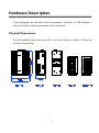
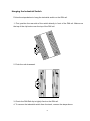
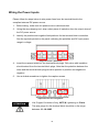
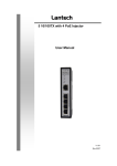
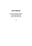
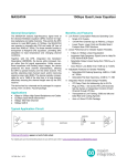
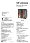
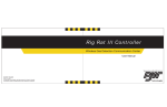
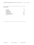
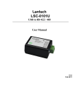
1
Lantech IPGS-0204G 4 10/100/1000T + 2 Giga SFP Industrial Switch w/4 PoE 802.3at Injectors User Manual FCC Warning This Equipment has been tested and found to comply with the limits for a Class-A digital device, pursuant to Part 15 of the FCC rules. These limits are designed to provide reasonable protection against harmful interference in a residential installation. This equipment generates, uses, and can radiate radio frequency energy. It may cause harmful interference to radio communications if the equipment is not installed and used in accordance with the instructions. However, there is no guarantee that interference will not occur in a particular installation. If this equipment does cause harmful interference to radio or television reception, which can be determined by turning the equipment off and on, the user is encouraged to try to correct the interference by one or more of the following measures: Reorient or relocate the receiving antenna. Increase the separation between the equipment and receiver. Connect the equipment into an outlet on a circuit different from that to which the receiver is connected. Consult the dealer or an experienced radio/TV technician for help. CE Mark Warning This is a Class-A product. In a domestic environment this product may cause radio interference in which case the user may be required to take adequate measures. Content Introduction ................................................................ 1 Features ................................................................... 1 Package Contents ................................................... 2 Hardware Description ............................................... 3 Physical Dimensions ............................................... 3 LED Indicators ......................................................... 4 RJ-45 Pin Assignments .......................................... 5 Installation .................................................................. 8 DIN-Rail Mounting ................................................... 8 Wall Mounting........................................................ 10 Grounding the Industrial Switch ............................ 11 Wiring the Power Inputs ...................................... 12 Wiring the Fault Alarm Contacts ......................... 13 Ethernet Cabling ................................................... 14 Troubleshooting ...................................................... 17 Technical Specifications ......................................... 18 Introduction The High-Power PoE Industrial Switch is a cost-effective solution, which meets the high reliability requirements demanded by industrial applications. To solve the inconvenience of wall outlet access, the equipment is designed with power over Ethernet ports complying with the IEEE 802.3at standard, providing each PoE port up to 30 watts for connected Powered Devices that need higher power consumption to receive power as well as data over the conventional RJ-45 cables. Features System Interface/Performance RJ-45 ports support Auto MDI/MDI-X Function Embedded 4-port PoE Injection Store-and-Forward Switching Architecture Back-plane (Switching Fabric): 12Gbps MAC Address Table with 8K entries Power Input DC 48V (48 ~ 57V) Redundant Power Input Case/Installation IP-30 Protection Installation in a Pollution Degree 2 environment DIN-rail and Wall mountings Design 1 Package Contents Please refer to the package contents list below to verify them against the checklist. PoE Industrial Switch x 1 User manual (CD-ROM) x 1 Removable Terminal Block x 1 Wall-mount Kit (2 wall-mount brackets with screws) x 1 Compare the contents of the industrial switch with the standard checklist above. If any item is damaged or missing, please contact the local dealer for service. 2 Hardware Description In this paragraph, the Industrial switch’s dimensions, definitions for LED indicators, cabling information, and wiring installation will be described. Physical Dimensions The PoE Industrial Switch dimensions (W x H x D) are 59.6mm x 152mm x 105mm as the figure shown below. 3 LED Indicators The diagnostic LED indicators located on the front panel of the industrial switch provide real-time system information and operation status. The table below provides the description status and definitions of the LED indicators for the switch. LED Color On Power input 1 is active Off Power input 1 is inactive On Power input 2 is active Off Power input 2 is inactive On Power input 1 or 2 has failed Off No failure occurs On The port is supplying power to the powered-device Off No powered-device attached or power supplying fails On Connected to network Flashing Networking is active Off Not connected to network Green On 1000M (lower) Off 100/10M On Connected to network Flashing Networking is active Off Not connected to network Power1 Green Power2 Green P-Fail Red PoE indicator (Port 1 ~ 4) Green Green 1~4 (upper) (RJ-45) 5, 6 (mini-GBIC) Description Green LED Indication Definition 4 RJ-45 Pin Assignments The UTP/STP ports will automatically sense for Fast Ethernet (10Base-T/100Base-TX) or Gigabit Ethernet (10Base-T/100Base-TX/1000Base-T) connection. Auto MDI/MDIX means that the switch can connect to another switch or workstation without changing straight through or crossover cabling. See the figures below for straight through and crossover cable schema. Note 10/100Base-TX Pinouts Pin Number Assignment 1 Tx+ 2 Tx- 3 Rx+ 6 Rx- “+” and “-” signs represent the polarity of the wires that make up each wire pair. The table below shows the 10Base-T/100Base-TX MDI and MDI-X port pinouts. Pin Number MDI-X Signal Name MDI Signal Name 1 Receive Data plus (RD+) Transmit Data plus (TD+) 2 Receive Data minus (RD-) Transmit Data minus (TD-) 3 Transmit Data plus (TD+) Receive Data plus (RD+) 6 Transmit Data minus (TD-) Receive Data minus (RD-) 5 10/100Base-TX Cable Schema Straight Through Cable Schema Crossover Cable Schema 10/100/1000Base-T Pinouts The table below describes the gigabit Ethernet RJ-45 pinouts. Pin Signal name Description 1 BI_DA+ Bi-directional pair A+ 2 BI_DA- Bi-directional pair A- 3 BI_DB+ Bi-directional pair B+ 4 BI_DC+ Bi-directional pair C+ 5 BI_DC- Bi-directional pair C- 6 BI_DB- Bi-directional pair B- 7 BI_DD+ Bi-directional pair D+ 8 BI_DD- Bi-directional pair D- 6 10/100/1000Base-T Cable Schema The following two figures illustrate the 10/100/1000Base-T cable schema. Straight Through Cable Schema Crossover Cable Schema 7 Installation ATTENTION This equipment is intended for use in a Pollution Degree 2 industrial environment. DIN-Rail Mounting Assembling the DIN-Rail Clip The DIN-rail clip is screwed on the industrial switch when out of factory. If not, please refer to the following steps to secure the DIN-rail clip on the switch. 1. Use the included screws to secure the DIN-rail clip on the industrial switch. 2. To remove the DIN-rail clip, reverse step 1. DIN-Rail Clip Rear side of the Switch 8 Hanging the Industrial Switch Follow the steps below to hang the industrial switch on the DIN rail. 1. First, position the rear side of the switch directly in front of the DIN rail. Make sure the top of the clip hooks over the top of the DIN rail. 2. Push the unit downward. 3. Check the DIN-Rail clip is tightly fixed on the DIN rail. 4. To remove the industrial switch from the track, reverse the steps above. 9 Wall Mounting To hang the Ethernet switch on the wall, please follow the steps below. 1. Remove the DIN-rail clip. 2. Prepare the two wall-mount plates and six screws included. 3. Align the screw holes bewteen the wall-mount plates and the unit as the figure illustrated. 4. Secure the plates to the unit with the accompanying screws. 10 Grounding the Industrial Switch Follow the instructions below to attach the industrial switch to ground. ATTENTION When installing the industrial switch, the ground connection must always be made first and disconnected last. 1. On the top of the industrial switch, locate and remove the dome screw which has a ground symbol beside it. 2. Attach the ground wire to the screw hole with the dome screw. 11 Wiring the Power Inputs Please follow the steps below to wire power lines from the terminal block to the compliant external DC power source. 1. Before wiring, make sure the power source is disconnected. 2. Using the wire-stripping tool, strip a short piece of insulation from the output wires of the DC power source. 3. Identify the positive and negative feed positions for the terminal block connection. See the symbols printed on the panel indicating the polarities and DC input power range in voltage. Plugs for Power 1 & Power 2 4. Insert the exposed wires into the terminal block plugs. Only wires with insulation should extend from the terminal block plugs. Note that the polarities between the wires and the terminal block plugs must be positive to positive and negative to negative. 5. Use a slotted screwdriver to tighten the captive screws. Captive Screws for Fixing Wires ATTENTION Use Copper Conductors Only, 60/75C, tightening to 5 lb-in The wire gauge for the terminal block should be in the range between 12~ 18 AWG. 12 Wiring the Fault Alarm Contacts The fault alarm plugs are in the middle of the terminal block, as the left picture shown below. With a Normally Close circuit formed by wiring with an external power and a warning device (a buzzer or a flashing LED), system will detect the fault status including the port linking failure (managed industrial switch only) and the power failure. Please refer to the right picture below, a wiring example for the fault alarm application. Terminal Block Plugs for Fault Alarm Contacts 24Vdc, 1A Resistance Fault Alarm Wiring Example 13 Ethernet Cabling Use the four twisted-pair, Category 5e or above cabling for RJ-45 port connection. The cable between the switch and the link partner (switch, hub, workstation, etc.) must be less than 100 meters (328 ft.) long. The small form-factor pluggable (SFP) is a compact optical transceiver used in optical communications for both telecommunication and data communication. Connecting the SFP Port To connect the transceiver and LC cable, please take the steps shown as follows: First, insert the transceiver into the SFP slot. Notice that the triangle mark indicates the bottom of the slot. Transceiver to the SFP slot 14 Transceiver Inserted Second, insert the fiber cable of LC connector into the transceiver. LC connected to the transceiver 15 Disconnecting the SFP Port To remove the LC connector from the transceiver, please follow the steps shown below: First, press the upper side of the LC connector from the transceiver and pull it out to release. Remove LC connector Second, push down the metal loop and pull the transceiver out by the plastic part. Pull out from the SFP slot 16 Troubleshooting Verify that you are using the included or appropriate power cord/supplier/adapter. Please don’t use the power supplier/adapter with a non-compliant DC output voltage, or it will burn the equipment. Select the proper UTP/STP cable to construct your network. Please check that you are using the right cable. Use unshielded twisted-pair (UTP) or shield twisted-pair (STP) cable for RJ-45 connections: 100Ω Category 3, 4 or 5 cable for 10Mbps connections, 100Ω Category 5 cable for 100Mbps connections, or 100Ω Category 5e/above cable for 1000Mbps. Also be sure that the length of any twisted-pair connection does not exceed 100 meters (328 feet). Diagnosing LED Indicators: To assist in identifying problems, the Switch can be easily monitored through LED indicators on the front panel, which describe common problems the user may encounter and where the user can find possible solutions. If the power indicator does not light on when the power cord is plugged in, users may have a problem with the power cord. Then check for loose power connections, power losses or surges at power outlet. If you still cannot resolve the problem, contact the local dealer for assistance. If the Ethernet LED indicators are normal and the connected cables are correct but the packets still cannot transmit, please check your system’s Ethernet devices’ configuration or status. 17 Technical Specifications IEEE 802.3 10Base-T Ethernet IEEE 802.3u 100Base-TX Fast Ethernet Standard IEEE 802.3ab 1000Base-T Gigabit Ethernet IEEE 802.3z 1000Base-X Gigabit Ethernet over Fiber-Optic IEEE802.3x Flow Control and Back Pressure IEEE802.3at Power over Ethernet Protocol Switch Architecture CSMA/CD Back-plane (Switching Fabric): 12Gbps Packet throughput ability (Full-Duplex): 17.85Mpps@64bytes 14,880 pps for Ethernet port Transfer Rate 148,800 pps for Fast Ethernet port 1,488,000 pps for Gigabit Ethernet port MAC Address Connector 8K-entry MAC address table 10/100/1000Base-T: 4 x RJ-45 1000Base-X: 2 x SFP RJ-45 port #1 ~ # 4 support IEEE 802.3at End-point, PoE Pin Assignments Alternative A mode. Each port provides 30W@55V power carring ability. Positive (VCC+): RJ-45 pin 1, 2. Negative (VCC-): RJ-45 pin 3, 6. Per unit: Power 1 (Green), Power 2 (Green), P-Fail (Red) LED Ethernet: Link/Activity (Green), Speed (Green), mini-GBIC: Link/Activity (Green), PoE (Green) 18 10Base-T: 2-pair UTP/STP Cat. 3, 4, 5, 5e, 6 cable EIA/TIA-568 100-ohm (100m) Network Cable 100Base-TX: 2-pair UTP/STP Cat. 5, 5e, 6 cable EIA/TIA-568 100-ohm (100m) 1000Base-T: 2-pair UTP/STP Cat. 5E/6 or above cable EIA/TIA-568 100-ohm (100m) Power Supply Power Consumption DC 48V (48~57V), redundant power with polarity reverse protection 129.9W Installation DIN-Rail mounting, Wall mounting Operating Temp. -40 to 75ºC (-40 to 167ºF) Operating Humidity 5% to 95% (Non-condensing) Storage Temp. -40 to 85ºC Dimensions IP-30, 59.6mm (W) x 152mm (H) x 105mm (D) FCC Class A EMC CE EN61000-4-2/3/4/5/6/8 CE EN61000-6-2 CE EN61000-6-4 IEC60068-2-32 (Free fall) Stability Testing IEC60068-2-27 (Shock) IEC60068-2-6 (Vibration) 19