1
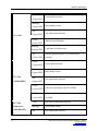
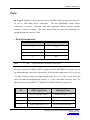
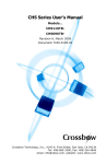
EIR418-2SFP-T User Manual Manual Documentation Number EIR418-2SFP-T – 0912m www.bb-elec.com www.bb-europe.com EIR418-2SFP-T Documentation Number: EIR418-2SFP-T- 0912m Using domestic and imported parts by International Headquarters B&B Electronics Mfg. Co. Inc. 707 Dayton Road Ottawa, IL 61350 USA Phone (815) 433-5100 -- General Fax (815) 433-5105 Website: www.bb-elec.com European Headquarters B&B Electronics Ltd. Westlink Commercial Park Oranmore, Co. Galway, Ireland Phone +353 91-792444 -- Fax +353 91-792445 Website: www.bb-europe.com ©2008 B& B Electronics Mfg. Co. Inc. No part of this publication may be reproduced or transmitted in any form or by any means, electronic or mechanical, including photography, recording, or any information storage and retrieval system without written consent. Information in this manual is subject to change without notice, and does not represent a commitment on the part of B&B Electronics Mfg. Co. Inc. B&B Electronics Mfg. Co. Inc. shall not be liable for incidental or consequential damages resulting from the furnishing, performance, or use of this manual. All Brand names used in this manual are the registered trademarks of their respective owners. The use of trademarks or other designations in this publication is for reference purposes only and does not constitute an endorsement by the trademark holder i Manual Documentation Number EIR418-2SFP-T – 0912m www.bb-elec.com www.bb-europe.com Table of Contents Table of Contents 1. Introduction ..................................................................................................................... 1 Features......................................................................................................................... 1 Package Contents ......................................................................................................... 2 2. Hardware Description..................................................................................................... 3 Physical Dimension ....................................................................................................... 3 Front Panel .................................................................................................................... 3 Top View ........................................................................................................................ 4 LED Indicators ............................................................................................................... 4 Ports .............................................................................................................................. 6 Cabling......................................................................................................................... 12 Wiring the Power Inputs .............................................................................................. 12 Wiring the Fault Alarm Contact.................................................................................... 13 3. Mounting Installation.................................................................................................... 14 DIN-Rail Mounting ....................................................................................................... 14 Wall Mount Plate Mounting.......................................................................................... 16 4. Hardware Installation ................................................................................................... 17 Installation Steps ......................................................................................................... 17 ii 5. Network Application ..................................................................................................... 18 6. Troubles shooting ........................................................................................................ 19 7. Technical Specification ................................................................................................ 20 Manual Documentation Number EIR418-2SFP-T – 0912m www.bb-elec.com www.bb-europe.com Introduction Introduction The EIR418-2SFP-T is an industrial DIN mount, unmanaged 18 port Ethernet switch with Gigabit capability. It has (16) 10/100 copper Ethernet ports and (2) Gigabit Combo ports that support copper or SFP module connections. Features • System Interface/Performance o RJ-45 ports support Auto MDI/MDI-X Function o SFP (mini-GBIC) supports 100/1000 Dual Mode o Store-and-Forward Switching Architecture o Back-plane (Switching Fabric): 7.2Gbps o 1Mbits Packet Buffer o 8K MAC Address Table o Supports Wide Operating Temperature -40oC to 75oC • Case/Installation o IP30 Protection o DIN-Rail and Wall Mount Design • Power Supply o Wide Range Redundant Power Design o Power Reverse Polarity Protected o Overload Current Protection 1 • Provides EFT protection 3,000 VDC for power line • Supports 6,000 VDC Ethernet ESD protection Manual Documentation Number EIR418-2SFP-T – 0912m www.bb-elec.com www.bb-europe.com Introduction Package Contents 2 • (1) EIR418-2SFP-T, 18 Port Gigabit Industrial Ethernet Switch • (1) Quick Start Guide • (1) CD ROM with User Manual • (2) Wall Mounting Bracket and Screws Manual Documentation Number EIR418-2SFP-T – 0912m www.bb-elec.com www.bb-europe.com Hardware Description Hardware Description Physical Dimension (W x D x H) is 72mm x 105mm x 152mm (2.8 x 4.1 x 6.0 inches) Front Panel The front panel of the EIR418-2SFP-T is shown below. 3 Manual Documentation Number EIR418-2SFP-T – 0912m www.bb-elec.com www.bb-europe.com Hardware Description Top View The top panel view of the EIR418-2SFP-T is equipped with one terminal block connector that consists of two 12 to 48 VDC power inputs and the fault alarm output. LED Indicators LED Status Meaning Green Power 1 is active Off No power at input 1 Green Power 2 is active Off No power at input 2 Red PWR1 or PWR2 has failed PWR1 PWR2 Fault Off 4 PWR1 & PWR2 are both active or no power is applied Manual Documentation Number EIR418-2SFP-T – 0912m www.bb-elec.com www.bb-europe.com Hardware Description Green (Upper LED) Connected to network Blinking (Upper LED) Off P1 to P16 (Upper LED) Yellow (Lower LED) Blinking (Lower LED) Not connected to network Ethernet port full duplex Collision of packets occurs Off Ethernet port half duplex or not connected to (Lower LED) network Green (Upper LED) Blinking (Upper LED) P17, P18 Off (10/100/1000T) (Upper LED) Green (Lower LED) Connected to network Networking is active Not connected to network The port is operating at speed of 1000M Off The port is disconnected or operates at speed of (Lower LED) 10/100M P17, P18 Green SFP port is connected to network Link/Active Blinking Networking is active Off Not connected to network (100/1000 SFP) 5 Networking is active Manual Documentation Number EIR418-2SFP-T – 0912m www.bb-elec.com www.bb-europe.com Hardware Description Ports RJ-45 ports: Eight RJ-45 ports auto-sense for 10, 100 Mbps while two ports auto-sense for 10, 100 or 1000 Mbps device connections. The auto MDI/MDIX feature allows connections to switches, workstation and other equipment without changing straight through or crossover cabling. The charts below show the cable pin assignments for straight through and crossover cables. • RJ-45 Pin Assignments Pin Number Assignment 1 Tx+ 2 Tx- 3 Rx+ 6 Rx- “+” and “-” signs represent the polarity of wire pair. Note All copper ports on the EIR418-2SFP-T support automatic MDI/MDI-X operation, you can use straight-through cables (See Figure below) for all network connections to PCs or servers, or to other switches or hubs. In straight-through cables, pins 1, 2, 3, and 6, at one end of the cable, are connected straight through to pins 1, 2, 3 and 6 at the other end of the cable. The table below shows the 10BASE-T / 100BASE-TX MDI and MDI-X port pin outs. 6 Pin MDI-X Signal Name MDI Signal Name 1 Receive Data plus (RD+) Transmit Data plus (TD+) 2 Receive Data minus (RD-) Transmit Data minus (TD-) 3 Transmit Data plus (TD+) Receive Data plus (RD+) 6 Transmit Data minus (TD-) Receive Data minus (RD-) Manual Documentation Number EIR418-2SFP-T – 0912m www.bb-elec.com www.bb-europe.com Hardware Description Straight Through Cable Schematic Cross Over Cable Schematic • 2 Gigabit Copper/SFP (Mini-GBIC) combo port: The EIR418-2SFP-T has two auto-detect Giga ports—copper/Fiber combo ports. The Gigabit Copper (10/100/1000T) ports should use Category 5e or above UTP/STP cable for connection. The SFP slots support dual mode which can switch the connection speed between 100 and 1000Mbps. These SFP slots can be used to connect the network segment with single or multi-mode fiber. You must choose appropriate mini-GBIC module to plug into the slots. Make sure the module is aligned correctly and then slide the module into the SFP slot until a click is heard. With the SFP module (fiber optic connection), the switch can transmits speed up to 1000 Mbps and you can prevent noise interference from the system and get extended transmission distance, depending on the SFP module used. Note The SFP/Copper Combo port can’t both be used at the same time. The SFP module has the highest priority. If a 1000M SFP transceiver is inserted into the SFP cage and a remote device is connected to the SFP port, the copper combo 7 Manual Documentation Number EIR418-2SFP-T – 0912m www.bb-elec.com www.bb-europe.com Hardware Description port will link down. If a 1OOM SFP transceiver is inserted into the SFP cage the copper combo port will link down regardless of the connection status of the remote device. RJ-45 Male Plug 8765432 1 12345678 12345678 RJ-45 Female Color standard EIAfTIA T568A Ethernet Patch Cable RJ45 Pin# TX+ r:.ill"':ii Green!White Tracer 1 TXGreen Orange!White 2 RX+ lt"Zl2] r:.ill"':ii - RX-[===:J r:.ill"':ii Color standard EIAfTIA T568A Tracer Blue 3 4 Blue!White Tracer 5 Orange 6 Brown!White Tracer 7 Brown 8 1 Green!White Tracer 2 Green 3 Orange!White Tracer 4 Blue 5 Blue!White Tracer 6 Orange 7 Brown!White Tracer 8 Brown Ethernet Crossover Cable RJ45 Pin# Green!White Tracer 1 Green 2 [t272] Orange!White Tracer 3 Blue 4 Blue!White Tracer 5 r:.ill"':ii Orange 6 [===:J r:.ill"':ii Brown!White Tracer 7 Brown 8 r:.ill"':ii Pin# RJ45 Pin# RJ45 1 Orange!White Tracer 2 Orange 3 Green!White Tracer 4 Brown!White Tracer 5 Brown 6 Green 7 Blue 8 Blue!White Tracer "A" is earlier 8 Manual Documentation Number EIR418-2SFP-T- 0912m \fVININ. bb-elec.com \fVININ. bb-europe.com Hardware Description Color standard EIAfTIA T568B TX+ I.?Z72J T><-c=::J R><+ R)(- ,........ Ethernet Patch Cable RJ45 Pin# Orange!White Tracer 1 Orange 2 Green!White Tracer J Blue 4 Green 6 Blue!White Tracer 5 - Pin# RJ45 1 Orange!White Tracer ]PR2 2 Orange J Green!White Tracer 4 Blue 6 Green -PRJ 5 Blue!White Tracer Brown!White Tracer 7 7 Brown!White Tracer 8 Brown Brown 8 Color standard Ethernet Crossover Cable EIAfTIA T568B RJ45 Pin# Green!White Tracer J Orange!White Tracer 1 Orange 2 Blue Blue!White Tracer Green Brown!White Tracer Brown "B" is most recent 9 4 5 6 Jl PR 1 riii"'\\\\J PR4 ,........ Pin# RJ45 1 Green!White Tracer 2 Green J Orange!White Tracer l7llZl 4 Brown!White Tracer 5 Brown 6 Orange c=::J 7 Blue 8 Blue!White Tracer ,........ ,........ 7 8 Common Ethernet Crossover Cables may only cross connect the Orange & Green pairs Manual Documentation Number EIR418-2SFP-T- 0912m \fVININ. bb-elec.com \fVININ. bb-europe.com Hardware Description To connect the transceiver and fiber cable, follow the steps shown below. (Note: SFP modules typically terminate with an LC fiber connector) First, insert the SFP transceiver into the SFP module cage. Notice that the triangle mark is at the bottom of the module. Make sure the module is aligned correctly and then slide the module into the SFP slot until a click is heard. Transceiver Inserted 10 Manual Documentation Number EIR418-2SFP-T – 0912m www.bb-elec.com www.bb-europe.com Hardware Description Second, insert the fiber cable into the transceiver. LC connector to the transceiver To remove the LC connector and SFP transceiver, follow the steps below: First, press the upper side of the LC connector down and pull it out before releasing Remove LC connector 11 Manual Documentation Number EIR418-2SFP-T – 0912m www.bb-elec.com www.bb-europe.com Hardware Description Second, swivel the metal latch away from the switch and pull the transceiver out. Pull out from the SFP module Cabling Use unshielded twisted-pair (UTP) or shielded twisted-pair (STP) cable. 10Mbps: Use category 3, 4, 5 or greater cable 100Mbps: Use category 5 or greater 1000Mbps: Use category 5e or greater cable Cable distances should be less than 100 meters (328 ft.) long. Wiring the Power Inputs Follow the steps below to insert the power wire. 1. Insert the positive and negative wires into the V+ and V- contacts on the terminal block connector. 12 Manual Documentation Number EIR418-2SFP-T – 0912m www.bb-elec.com www.bb-europe.com Hardware Description 2. Tighten the wire-clamp screws for prevent the wires from becoming loose. Wiring the Fault Alarm Contact The fault alarm contact is in the middle of the terminal block connector as shown below. If one of the power sources fails a fault will be detected causing the circuit to open. Insert the wires into the fault alarm contact (No. 3 & 4) Note 13 The wire gauge for the terminal block should be 12 to 24 AWG. Manual Documentation Number EIR418-2SFP-T – 0912m www.bb-elec.com www.bb-europe.com Mounting Installation Mounting Installation DIN-Rail Mounting The DIN rail clip comes screwed on to the switch, from the factory. If the DIN rail clip is not screwed on the switch, please see the following figure to re-attach the DIN-Rail clip. Then follow the steps below to hang the switch onto a DIN rail. 14 1. Use the screws to screw the DIN rail clip onto the switch. 2. To remove the DIN rail clip, reverse step 1. Manual Documentation Number EIR418-2SFP-T – 0912m www.bb-elec.com www.bb-europe.com Mounting Installation 3. First, insert the top of DIN rail clip onto the piece of the DIN rail track. 4. Then, lightly push the bottom of the switch so it can snap the rest of the way onto the DIN rail track. 5. Check that the switch is held tightly to the DIN rail track. 6. To remove the switch from the track, reverse the steps above. • First pushing down lightly on the switch will give enough room for the bottom of the switch to clear the bottom of the DIN rail track. 15 Manual Documentation Number EIR418-2SFP-T – 0912m www.bb-elec.com www.bb-europe.com Mounting Installation • Pulling slowly at the bottom of the switch will bring the switch out so that the switch can now be carefully lifted off the DIN rail track. Wall or Panel Mount Plate Mounting Follow the steps below to mount the switch with the wall mount plate. 1. Remove the DIN rail clip from the switch; loose the screws to remove the DIN rail clip. 2. Place the wall mount plate on the rear panel of the switch. 3. Use the screws to screw the wall mount plate onto the switch. 4. Use the hook holes at the corners of the wall mount plates to hang the industrial switch on the wall. 5. To remove the wall mount plate, reverse the above steps. 16 Manual Documentation Number EIR418-2SFP-T – 0912m www.bb-elec.com www.bb-europe.com Hardware Installation Hardware Installation Installation Steps 1. Unpack the switch. 2. Check if the DIN rail clip is screwed on the Industrial switch or not. If the DIN rail clip is not screwed onto switch, please refer to DIN-Rail Mounting section for DIN-Rail installation. If the user wants to wall mount or panel mount the switch, then please refer to Wall or Panel Mount Plate Mounting section for wall plate installation. 3. To hang the Industrial switch on the DIN-Rail track or wall, please refer to the Mounting Installation section. 4. Power on the Industrial switch. Please refer to the Wiring the Power Inputs section for knowing the information about how to wire the power. The power LED on the Industrial switch will light up. Please refer to the LED Indicators section for indication of LED lights. 5. Prepare the twisted-pair, straight through Category 5/above cable for Ethernet connection. 6. Insert one end of UTP/STP cable into the Industrial switch RJ-45 port and the other end to the network device’s RJ-45 port, e.g. Switch PC or Server. The RJ-45 port LED on the Industrial switch will light up when the cable is connected with the network device. Please refer to the LED Indicators section for LED light indication. 7. When all connections are set and LED lights all show in normal, the installation is complete. 17 Manual Documentation Number EIR418-2SFP-T – 0912m www.bb-elec.com www.bb-europe.com Network Application Network Application The diagram below shows a typical switch installation for the EIR418-2SFP-T. 18 Manual Documentation Number EIR418-2SFP-T – 0912m www.bb-elec.com www.bb-europe.com Troubleshooting Troubleshooting • Verify that you are using a power supply ranging from 12 to 48VDC. Applying more than 48VDC could cause damage to the switch. • Be sure the proper cable is used in your network. Refer to the Cabling section of this manual for help. • Diagnosing LED Indicators: The switch can be monitored through the LED indicators on the front panel of the switch. The LED’s can help describes common problems you may encounter and where you may find possible solutions, to assist in identifying problems. • If the power indicators do not light on when power is applied, you may have a problem with the power supply. Check for loose power connections, power losses or surges at the power outlet. • If the switch LED’s represent normal operating mode and the cable connections are correct and no data is transmitted or received through the switch, contact your Network Administrator for network configuration and status help. 19 Manual Documentation Number EIR418-2SFP-T – 0912m www.bb-elec.com www.bb-europe.com Technical Specification Technical Specification IEEE 802.3 10Base-T IEEE 802.3u 100Base-TX Standard IEEE 802.3ab 1000Base-T IEEE 802.3z Gigabit fiber IEEE 802.3x Flow Control and Back-pressure Protocol CSMA/CD 14,880 pps for 10Base-T Ethernet port Transfer Rate 148,800 pps for 100Base-TX/FX Fast Ethernet port 1,488,000 pps for Gigabit Fiber Ethernet port MAC address 8K MAC address table Packet Buffer 1Mbits Per unit: Power 1 (Green), Power 2 (Green), Fault (Red) 16 10/100TX: Link/Activity (Green), Full duplex/Collision LED (Yellow) Gigabit Copper: Link/Activity (Green), speed (1000M Green) SFP: Link/Activity (Green) 10Base-T: 2-pair UTP/STP Cat. 3, 4, 5 cable EIA/TIA-568 100-ohm (100m) Network Cable 100Base-TX: 2-pair UTP/STP Cat. 5 cable EIA/TIA-568 100-ohm (100m) 1000Base-T: 2-pair UTP/STP Cat. 5e or 6 cable EIA/TIA-568 100-ohm (100m) 20 Manual Documentation Number EIR418-2SFP-T – 0912m www.bb-elec.com www.bb-europe.com Technical Specification Optical cable Back-plane Packet throughput ability Multi-mode: 50/125um or 62.5/125um Single mode: 9/125um 7.2Gbps 10.7Mpps at 64bytes 12 to 48 VDC Power Supply Redundant power with polarity reverse protection and removable terminal block Power Consumption Install 9 Watts DIN rail kit for DIN-type cabinet and wall mount ear for wall mount install Operating Temp. -40oC to 75oC Operating Humidity 5% to 95% (Non-condensing) Storage Temperature Case Dimension -40oC to 85oC IP30, 72 mm (W) x 105 mm (D) x 152mm (H) (2.8 x 4.1 x 6.0 inches) FCC Class A CE EN61000-4-2 (ESD) CE EN61000-4-3 (RS) EMI CE EN61000-4-4 (EFT) CE EN61000-4-5 (Surge) CE EN61000-4-6 (CS) CE EN61000-4-8 21 Manual Documentation Number EIR418-2SFP-T – 0912m www.bb-elec.com www.bb-europe.com Technical Specification CE EN61000-4-11 CE EN61000-4-12 CE EN61000-6-2 CE EN61000-6-4 UL cUL Safety CE/EN60950-1 IEC60068-2-32 (Free fall) Stability testing IEC60068-2-27 (Shock) IEC60068-2-6 (Vibration) 22 Manual Documentation Number EIR418-2SFP-T – 0912m www.bb-elec.com www.bb-europe.com