1
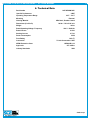
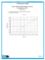
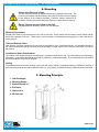
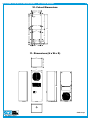
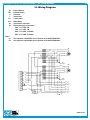
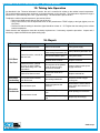
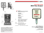
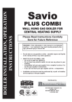
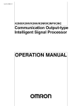
BSAGINAW
CONTROL & ENGINEERING • A/C USER MANUAL
User Manual SCE-HE04W120V
1. User Manual............................................................................................. p. 2
2. Legal Regulations.................................................................................... p. 2
3. Safety Instructions.................................................................................. p. 3
4. Technical Information.............................................................................. p. 4
5. Functional Principle................................................................................ p. 4
6. Technical Data.......................................................................................... p. 5
7. Performance Graph................................................................................. p. 6
8. Mounting................................................................................................... p. 7
9. Mounting Principle.................................................................................. p. 7
10. Cutout Dimensions.................................................................................. p. 8
11.Dimensions (H x W x D).......................................................................... p. 8
12. Electrical Connection.............................................................................. p. 9
13.Controller Programming......................................................................... p. 9
14.Wiring Diagram........................................................................................ p. 10
15.Taking Into Operation.............................................................................. p. 11
16. Repair........................................................................................................ p. 11
17.Maintenance & Cleaning......................................................................... p. 12
18.Transportation & Storage........................................................................ p. 13
19. Parts Supplied.......................................................................................... p. 13
20. Warranty / Limits of Liability.................................................................. p. 14
1
BSAGINAW
CONTROL & ENGINEERING • A/C USER MANUAL
2
1. User Manual
This instruction manual contains information and instructions to enable the user to work safely, correctly and economically
on the unit. Understanding and adhering to the manual can help one:
• Avoid any dangers
• Reduce repair costs and stoppages
• Extend and improve the reliability and working life of the unit
PLEASE ENSURE TO USE THE RIGHT VERSION OF THE INSTRUCTION MANUAL SUITABLE FOR YOUR UNIT
Conditions of Use
The unit is to be used exclusively for the dissipation of heat from control cabinets and enclosures in order to protect
temperature sensitive components in an industrial environment. To meet the conditions of use, all the information and
instructions in the instruction manual must be adhered to.
General Danger
Indicates compulsory safety regulations which are not covered by a specific pictogram such
as one of the following.
High Electric Voltage
Indicates electric shock danger.
Important Safety Instruction
Indicates instructions for safe maintenance and operation of the unit.
Attention
Indicates possible burns from hot components.
Attention
Indicates possible damage to the unit.
Instruction
Indicates possible danger to the environment.
2. Legal Regulations
Liability
The information, data and instructions contained in this instruction manual are current at the time of going to press. We
reserve the right to make technical changes to the unit in the course of its development. Therefore, no claims can be
accepted for previously delivered units based on the information, diagrams or descriptions contained in this manual. No
liability can be accepted for damage and production caused by:
• Disregarding the instruction manual
• Operation error
• Inappropriate work on or with the unit
• The use of non-specified spare parts and accessories
• Unauthorized modifications or changes to the unit by the user or his personnel
Saginaw Control & Engineering is only liable for errors and omissions as outlined in the guarantee conditions contained in
the main contractual agreement. Claims for damages on any grounds are excluded.
back to top
BSAGINAW
CONTROL & ENGINEERING • A/C USER MANUAL
3
3. Safety Instructions
Upon delivery the unit is already meeting current technical standards, therefore it can be safely taken into operation. Only
trained specialists are allowed to work on the unit. Unauthorized personnel must be prohibited from working on the unit.
Operating personnel must inform their superiors immediately if any malfunction of the unit becomes apparent.
Please note that before starting to work on or with the unit, a procedure must be carried out inside the cabinet on which the
unit is to be mounted.
Before commencing work inside the cabinet, the control cabinet manufacturer’s instruction must be read with regards to:
• Safety instructions
• Instructions on taking the cabinet out of operation
• Instructions on the prevention of unauthorized cabinet reconnection
The electric equipment meets the valid safety regulations. One can find dangerous voltage (above 50V AC or above 100V
DC):
• Behind the control cabinet doors
• On the power supply in the unit housing
The units have to be fused according to the type plate and the wiring diagram. Switch the unit off immediately if the electric
power supply is interrupted.
Danger Through Incorrect Work on the Unit
Only specialized personnel are allowed to maintain and clean the unit. Regular maintenance
and cleaning must be kept in order to ensure that the unit remains in perfect working condition
and has a long working life.
Danger from Electric Voltage
Only specialized personnel are allowed to maintain and clean the unit. The personnel must
ensure that for the duration of the maintenance and cleaning, the unit is disconnected from
the electrical supply.
Attention
Damage to the unit through the use of inappropriate cleaning materials. Please do not use
aggressive cleaning material.
Instruction
Damage to the environment through unauthorized disposal. All spare parts and associated
material must be disposed of according to the environmental laws.
back to top
BSAGINAW
CONTROL & ENGINEERING • A/C USER MANUAL
4
4. Technical Information
Concise Unit Description
Heat Exchangers are used where the heat generated by energy losses in control cabinets must be conducted away to
protect temperature-sensitive components. The characteristics graph shown in the “Performance Characteristics” section
applies to external (ambient) air as the coolant
In Air-to-Air Heat Exchangers, the internal temperature of the control cabinet cannot be cooler than the ambient temperature.
There are natural limits to the cooling performance, dependent on the air supply temperature and the requirement for a
temperature difference of at least 9° F. Unlike systems in which the heat generated is allowed to escape by air convection
through ventilation slots, with the Heat Exchanger, the clean air inside the control cabinet is prevented from mixing with the
air outside, which may well be unclean.
5. Functional Principle
Functional Principle
The Heat Exchanger is a cooling device that creates a heat-transfer through a large area of thin aluminum sheet metal
folded up in the Heat Exchanger core by means of forced convection. Used within an enclosure, it uses the ambient air as
the cooling medium, thus avoiding the utilization of refrigerant.
The cooling performance of the Heat Exchanger is dependant on the ambient (external) air temperature. The internal fan
is set to be always on. The external fan is controlled via a controller. When the cabinet temperature increases beyond the
pre-set thermostat temperature, the external fan is switched on and the Heat Exchanger starts cooling. Cooling stops when
the cabinet temperature cools below the pre-set temperature. Switching difference is 5.4° F.
back to top
BSAGINAW
CONTROL & ENGINEERING • A/C USER MANUAL
5
6. Technical Data
Part Number
Specific Performance
Operating Temperature Range Mounting Housing Material Dimensions (H x W x D) Weight
Rated Operating Voltage / Frequency SCE-HE04W120V
4 W/F
23°F - 131°F
External
Mild Steel, Powder Coated
20.00 x 7.50 x 5.95 inch
14 lbs
120 V - 50/60 Hz
Rated Current
0.48 A
Starting Current
0.70 A
Power Consumption
55 W
Fuse Rating
1.6 A (T)
Connection 70 inch Connection Cable
NEMA Protection Class
Approvals
Industry Standards
NEMA 3R & 12
CE / cURus
IS22
back to top
CONTROL & ENGINEERING • A/C USER MANUAL
6
7. Performance Graph
Enviro-Therm Heat Exchangers 4 W/F
Performance Curve
®
SCE-HE04W120V
T = Temperature difference between ambient and internal temperature
P = Heat Exchanger performance
Δ T (°C)
1100
-18
-12
-7
-1
4
10
16
21
27
0
10
20
30
40
50
60
70
80
1000
900
800
P (BTU/hr)
BSAGINAW
700
600
500
400
300
200
100
0
Δ T (°F)
back to top
BSAGINAW
CONTROL & ENGINEERING • A/C USER MANUAL
7
8. Mounting
Danger from Electrical Voltage
The unit must be mounted by specialized personnel (qualified electricians). The
personnel must ensure that the cabinet is disconnected from the electrical supply
for the duration of the mounting operation. Therefore, take the cabinet out of
operation, following the relevant instructions before mounting work commences.
Danger Through Incorrect Work on the Unit
Only specialists are allowed to put the unit into operation.
Mounting Preparations
Several points must be checked before the unit can be mounted. These checks must be made to ensure safety and the
trouble-free operation of the unit. These checks must be carried out with absolute thoroughness to ensure that the unit
works perfectly.
Transport Damage Check
Upon delivery, the carton containing the unit must be examined for signs of transport damage. Any transport damage to
the carton could indicate that the unit itself has been damaged in transit, which in the worst case could mean the unit will
not function.
Location and Space Requirements
The location of the cabinet must allow for sufficient air circulation to and from the unit. The unit should be mounted roughly
horizontally. It is therefore advisable to check that the cabinet is in a horizontal position. The max deviation from the vertical
or horizontal should not exceed 20 degrees.
Sealing
To guarantee that the unit works perfectly, ensure that the control cabinet is completely sealed (min NEMA 12) and that a
good seal exists between the control cabinet and the unit. If necessary, the cabinet mounting surface should be reinforced.
9. Mounting Principle
1. Heat Exchanger
2. Mounting Gasket
3. Slotted Stud M6 x 1”
4.Enclosure
5. Washer A6.4
6. M6 Lock Nut
back to top
BSAGINAW
CONTROL & ENGINEERING • A/C USER MANUAL
8
10. Cutout Dimensions
7.50
6.00
.75
.75
.75
.312
(x6)
9.90
8.50
6.63
.43
.43
.65
20.00
6.00
.75
.75
10.00
9.67
1.56
1.56
4.38
.43
1.40
.75
.75
6.00
.75
11. Dimensions (H x W x D)
7.50
6.00
7.74
20.16
back to top
BSAGINAW
CONTROL & ENGINEERING • A/C USER MANUAL
9
12. Electrical Connection
Door Switch
The unit can be switched on and of via a door contact switch. When delivered the door contact terminals are bridged on the
female connector. To connect the door contact switch, remove the bridge and connect door contact switch. The contact must
be closed when the cabinet door is closed.
13. Controller Programming
Controller
The unit is equipped with a temperature controller which regulates the function of the refrigeration cycle. In normal working
conditions, the display shows the temperature inside the enclosure. The controller “set point” for the interior of the enclosure
(parameter St / St1) is pre-set at 95°F and can be adjusted between 68°F and 122°F.
The High Temperature Alarm (parameter AH) is preset at 131°F. The High Temperature Alarm relay is delivered as “normally
closed” (H1=1). If you need to change it to “normally open”, please modify value of parameter H1 (H1=2).
Modifying Controller Parameters
1. Press the SET button for more than 3 sec. (if there are active alarms, mute the buzzer).The display shows the parameter
code ‘PS’ (password).
2. Only for parameters requiring password: Press the SET button to access the password setting, use the UP and DOWN
buttons to scroll the numbers until displaying, “22” (default password to access the parameters), press the SET button to
confirm the password.
3. Use the UP and DOWN buttons to scroll the parameters. The LED corresponding to the category of parameters will be on.
4. Press SET to display the value associated with the parameter.
5. Increase or decrease the value using the UP or DOWN button respectively.
6. Press SET to temporarily save the new value.
7. Press the SET button for more than 3 sec. to permanently save the new parameters and exit the parameter setting
procedure.
If no button is pressed for 60 sec. all changes made to the parameters, temporarily saved in the RAM, will be cancelled and
the previous settings restored. The cooling unit manufacturer is in no way liable for any alterations the customer may make
to the factory set parameters, unless the manufacturer has authorized the customer in writing to change them.
This manual is intended as quick reference for controller programming, for a full controller manual or if you need to restore
the factory parameters please go to our website to download the full manual or to locate your nearest servicing office.
back to top
BSAGINAW
CONTROL & ENGINEERING • A/C USER MANUAL
10
14. Wiring Diagram
IB
Internal Blower
EB
External Blower
CController
TTransformer
CC
7-Core Cable
AR
Alarm Relay
X3
Transformer Connector
X4
Electrical Supply Connections
230V 1: L1 230V, 3:N
120V 1: L1 120V, 3:N
460V 1: L1 460V, 3:L2 460V
400V 1: L1 400V, 3:L2 400V
Notes:
#1
The Capacitor and BN Wire are not present in the SCE-HE04W120V
#2
The Capacitor and BN Wire are not present in the SCE-HE04W120V
IB
GNYE
GNYE
BU
GNYE
BU
BK
BU
BK
BN
BU
BK
#1
EB
GNYE
BU
BK
1
BN
2
GY
3
WH
BN
4
5
BK
6
GY
7
BU
#2
8
RD
C
BK
10
11
P1
GY
P2
GNYE E
YE
9
BN
PK
230V
N
115V
T
BU
N
BK
L
RD
T1
PK
T2
CC
back to top
BSAGINAW
CONTROL & ENGINEERING • A/C USER MANUAL
11
15. Taking Into Operation
As described in the “Technical Information” section, the unit is controlled in relation to the cabinet internal temperature.
The required cabinet temperature can be set on the potentiometer on the controller. The temperature adjustment range is
between 32°F (left-hand stop) and 140°F (right-hand stop). The thermostat is pre-set at 95°F.
To adjust the cabinet internal temperature, proceed as follows:
• Remove the MCB access plate on the front of the unit
• Using a screw driver, turn the adjustment wheel on the potentiometer “TEMP” slightly to the right (higher) or to the
left (lower)
• Please note that the setting for the alarm signal should be at least 41 - 50°F higher than the setting for the cabinet
internal temperature
Check that the new adjustment meets the necessary requirements. If necessary, repeat the procedure. Inspect and, if
necessary, replace the MCB Access plate sealing tape.
16. Repair
Failure
Condition
Cause
Solution
Internal fan does not work
Power not connected.
Verify power supply
Enclosure temperature is
below setting temperature (St)
Verify values of parameter "St"
Door switch contact is open
Verify door switch
Controller does not work
Replace controller
Internal fan works, external
fan does not work. Display
shows alternating "OFF" and
temperature
The sequence of the phases
inside the power supply
connector is incorrect
Change phases inside power
supply connector
External fan does not work
External fan needs to be
replaced
Replace external fan
Unit cooling undersized
Enclosure needs a bigger
cooling unit
Ambient air gets into the
enclosure
Ensure door is closed, add a
door switch and connect it to
controller
Enclosure IP degree minimum
IP54
Seal openings on enclosure
Damaged/misplaced sealing
strip
Repair strip accordingly
Internal fan works, external fan
does not work
Unit Does
Not Cool
Enclosure Fans (external and internal)
Overheating work all the time
Door enclosure open
Excessive
Condensate
Door enclosure closed
back to top
BSAGINAW
CONTROL & ENGINEERING • A/C USER MANUAL
12
17. Maintenance & Cleaning
Danger from Electrical Voltage
Maintenance and cleaning must be carried out by specialists (electricians). The
personnel must ensure that for the duration of this work, the unit and the cabinet
are disconnected from the electrical supply and protected against unauthorized
reactivation.
Danger Through Incorrect Work on the Unit
The instructions in the cabinet manufacturer’s manual must be adhered to!
Damage to the Unit Through Maintenance and Repair
Maintenance and repair must be carried out by the manufacturer or another specialist.
Fan Replacement
The rated life expectancy of the fan is L10 = 30,000 hours under normal operating conditions.
To replace the internal or external fan, please proceed with the following:
• Remove the internal access panel by unscrewing the 10 fixing screws
• Disconnect the blower cables from the connectors
• Unscrew the four screws fixing the blower bracket to the cabinet
• Unscrew the fan from the bracket
• Re-assemble with the new blower in reverse order
Make sure that the blower cable length is the same as the one on the fan removed to ensure that the cable does not come
in contact with the blower while in operation. Make sure that the correct polarity is maintained (refer to circuit diagram). Inspect and, if necessary, replace the internal access panel sealing tape.
back to top
BSAGINAW
CONTROL & ENGINEERING • A/C USER MANUAL
13
18. Transportation & Storage
Malfunction Due to Transport Damage
On delivery the carton containing the unit must be examined for signs of transport
damage. Any transport damage to the carton could indicate that the unit itself has
been damaged in transit, which in the worst case could mean that the unit will not
function.
Storage Conditions
The unit can only be stored in locations which meet the following conditions:
Temperature Range: 104˚F to 158˚F
Relative Humidity (at 77˚F): Max 95%
Returning the Unit
Damage to the Unit Through Incorrect Transport
To avoid transport damage the unit should be returned in the original packaging or in
a packing case and must be strapped to a pallet!
If the unit cannot be returned in the original packaging, please ensure that:
• A space of at least 30 mm. must be maintained at all points between the unit and the external packaging
• The unit must be firmly fixed in the packaging
• The unit must be protected sufficiently by shock absorbing padding (hard foam corner pieces, strips, or cardboard
corner pieces)
19. Parts Supplied
1 x Heat Exchanger
1 x Instruction Manual with technical information
1 x EC Declaration
1 x Installation pack containing:
6 x Slotted Studs M6 x 25
6 x Washers A6.4 DIN 125
6 x Lock Nuts M6 DIN 985
1 x Tight Tape
1 x Drain Connector
1 x O-ring
Saginaw Control and Engineering
95 Midland Road
Saginaw, MI 48638-5770
Phone: (989) 799-6871
Fax: (989) 799-4524
[email protected]
back to top
BSAGINAW
CONTROL & ENGINEERING • A/C USER MANUAL
14
20. Warranty / Limits of Liability
All goods manufactured by SCE shall be warranted to be free of defects in material or workmanship for a period of two years
from the date of shipment. Should the product be proven to SCE to be defective, we shall option to repair or replace the
product. At no time will SCE reimburse purchaser for unauthorized rework on any product.
Air Conditioners & Heat Exchangers are warranted on parts and service for a period of two years from the date of shipment
by Saginaw Control and subject to the following conditions and exclusions:
All Goods must be installed and operated according to the following specifications: Maximum voltage variation no
greater than plus or minus 10% of nominal rating; Maximum frequency variation no greater than plus or minus 3
Hz. from nominal rating; Must not exceed minimum and maximum rated temperatures; Must not exceed (BTU/Hr)
rating; Filters must be cleaned regularly; Must be installed and grounded in accordance with all relevant electrical
and safety codes, as well as the National Electric Code and OSHA rules and regulations; Must be installed in a
stationery application, free of vibration.
Our warranty does not warranty product that has been modified, subjected to abuse, negligence in operation or
maintenance, or if product is used in a manner that exceeds its designed capabilities and rating.
Warranty related claims will be returned to the factory for evaluation and final disposition of the claim, any replacement parts
will be invoiced at standard pricing and credit issued for the returned product. If the product has been found to have been
modified, subjected to abuse, negligence in operation or maintenance, or if product has been used in a manner that exceeds
its designed capabilities and rating, credit may be reduced, denied or additional cost may be assessed and passed on to the
purchaser, such as return freight.
back to top