1
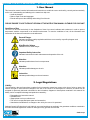
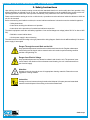
BSAGINAW
CONTROL & ENGINEERING • A/C USER MANUAL
User Manual SCE-AC1870B120V & SCE-AC1870B120VSS
1. User Manual............................................................................................. p. 2
2. Legal Regulations.................................................................................... p. 2
3. Safety Instructions.................................................................................. p. 3
4. Functional Principle................................................................................ p. 4
5. Technical Data.......................................................................................... p. 5
6. Performance Graph................................................................................. p. 6
7. Mounting................................................................................................... p. 7
8. Mounting Principle.................................................................................. p. 7
9. Cutout Dimensions.................................................................................. p. 8
10.Dimensions (H x W x D).......................................................................... p. 8
11. Electrical Connection.............................................................................. p. 9
12.Controller Programming......................................................................... p. 9
13.Wiring Diagram........................................................................................ p. 10
14.Taking Into Operation.............................................................................. p. 11
15. Repair........................................................................................................ p. 11
16.Maintenance & Cleaning......................................................................... p. 12
17.Transport & Storage................................................................................ p. 12
18. Parts Supplied.......................................................................................... p. 12
19. Warranty / Limits of Liability.................................................................. p. 13
1
BSAGINAW
CONTROL & ENGINEERING • A/C USER MANUAL
2
1. User Manual
This instruction manual contains information and instructions to enable the user to work safely, correctly and economically
on the unit. Understanding and adhering to the manual can help one:
• Avoid any dangers
• Reduce repair costs and stoppages
• Extend and improve the reliability and working life of the unit
PLEASE ENSURE TO USE THE RIGHT VERSION OF THE INSTRUCTION MANUAL SUITABLE FOR YOUR UNIT
Conditions of Use
The unit is to be used exclusively for the dissipation of heat from control cabinets and enclosures in order to protect
temperature sensitive components in an industrial environment. To meet the conditions of use, all the information and
instructions in the instruction manual must be adhered to.
General Danger
Indicates compulsory safety regulations which are not covered by a specific pictogram such
as one of the following.
High Electric Voltage
Indicates electric shock danger.
Important Safety Instruction
Indicates instructions for safe maintenance and operation of the unit.
Attention
Indicates possible burns from hot components.
Attention
Indicates possible damage to the unit.
Instruction
Indicates possible danger to the environment.
2. Legal Regulations
Liability
The information, data and instructions contained in this instruction manual are current at the time of going to press. We
reserve the right to make technical changes to the unit in the course of its development. Therefore, no claims can be
accepted for previously delivered units based on the information, diagrams or descriptions contained in this manual. No
liability can be accepted for damage and production caused by:
• Disregarding the instruction manual
• Operation error
• Inappropriate work on or with the unit
• The use of non-specified spare parts and accessories
• Unauthorized modifications or changes to the unit by the user or his personnel
Saginaw Control & Engineering is only liable for errors and omissions as outlined in the guarantee conditions contained in
the main contractual agreement. Claims for damages on any grounds are excluded.
back to top
BSAGINAW
CONTROL & ENGINEERING • A/C USER MANUAL
3
3. Safety Instructions
Upon delivery the unit is already meeting current technical standards therefore it can be safely taken into operation. Only
trained specialists are allowed to work on the unit. Unauthorized personnel must be prohibited from working on the unit.
Operating personnel must inform their superiors immediately if any malfunction of the unit becomes apparent.
Please note that before starting to work on or with the unit, a procedure must be carried out inside the cabinet on which the
unit is to be mounted.
Before commencing work inside the cabinet, the control cabinet manufacturer’s instruction must be read with regards to:
• Safety instructions
• Instructions on taking the cabinet out of operation
• Instructions on the prevention of unauthorized cabinet reconnection
The electric equipment meets the valid safety regulations. One can find dangerous voltage (above 50V AC or above 100V
DC):
• Behind the control cabinet doors
• On the power supply in the unit housing
The units have to be fused according to the type plate and the wiring diagram. Switch the unit off immediately if the electric
power supply is interrupted.
Danger Through Incorrect Work on the Unit
Only specialized personnel are allowed to maintain and clean the unit. Regular maintenance
and cleaning must be kept in order to ensure that the unit remains in perfect working condition
and has a long working life.
Danger from Electric Voltage
Only specialized personnel are allowed to maintain and clean the unit. The personnel must
ensure that for the duration of the maintenance and cleaning, the unit is disconnected from
the electrical supply.
Attention
Damage to the unit through the use of inappropriate cleaning materials. Please do not use
aggressive cleaning material.
Instruction
Damage to the environment through unauthorized disposal. All spare parts and associated
material must be disposed of according to the environmental laws.
back to top
BSAGINAW
CONTROL & ENGINEERING • A/C USER MANUAL
4
4. Functional Principle
The unit functions on the principle of the compression refrigerator. The main components are: refrigerant compressor,
condenser, choke and evaporator. These four components of the refrigerant plant are connected with each other by pipes
to form a hermetically sealed system in which the refrigerant (R134a) circulates.
1. Air Intake, Cabinet Side
2. Radial Fan, Cabinet Side
3.Evaporator
4. Air Outlet, Cabinet Side
5.Compressor
6. Air Intake, Ambient Side
7. Radial Fan, Ambient Side
8.Condenser
9. Air Outlet, Ambient Side
10. Filter Dryer
11. Expansion Valve
back to top
BSAGINAW
CONTROL & ENGINEERING • A/C USER MANUAL
5
5. Technical Data
Part Numbers
SCE-AC1870B120V
SCE-AC1870B120VSS
Cooling Capacity @ 95°F / 95°F
1870 BTU (548 Watts)
Cooling Capacity @ 131°F / 131°F
1877 BTU (550 Watts)
Heating Capacity 400 W
Compressor Reciprocating Compressor
Refrigerant R134a
Refrigerant Charge 5.29 oz
Max. Pressure
348 psig
Operating Temperature Range Max. Air Volume Flow
Ambient Air Circuit: 185 cfm
Cabinet Air Circuit: 97 cfm
Mounting External
Housing Material Mild Steel, Powder Coated
SS: Stainless Steel AISI 304 (1.4301)
Dimensions (H x W x D) 32.68 x 12.00 x 10.63 inch
Weight
71.5 lbs
Cutout Dimensions 10.43 x 7.09 inch
10.43 x 6.30 inch
Rated Operating Voltage / Frequency Rated Current @ 95°F / 95°F
-4°F - 131°F
120 V - 60 Hz
5.6 A
Starting Current
20 A
Max. Current
5.3 A
Power Consumption @ 95°F / 95°F
440 W
Max. Power Consumption 560 W
Fuse Rating
8 A (T)
Connection Connection Terminal Block
NEMA Protection Class
NEMA 3, 3R, 4 & 12
SS: NEMA 3, 3R, 4, 4X & 12
Approvals
Industry Standards
CE / cURus
IS19
SS: IS20
back to top
BSAGINAW
CONTROL & ENGINEERING • A/C USER MANUAL
6
6. Performance Graph
Enviro-Therm Air Conditioners 1870 BTU/HR (548Watts)
Performance Curve
®
SCE-AC1870B230V, SCE-AC1870B120V, SCE-AC1870B460V
SCE-AC1870B230VSS, SCE-AC1870B120VSS, SCE-AC1870B460VSS
Enclosure Air Temp
131°F/55°C
122°F/50°C
95°F/35°C
68°F/20°C
Ambient Temperature (°C)
18
24
29
35
41
46
52
57
879
2000
586
1500
439
1000
293
(BTU)
732
500
65
75
85
95
105
115
125
(Watt)
2500
Cooling Capacity
Cooling Capacity
3000
146
135
Ambient Temperature (°F)
back to top
BSAGINAW
CONTROL & ENGINEERING • A/C USER MANUAL
7
7. Mounting
Always disconnect the power supply before opening the unit.
Heat load to be dissipated from enclosure should not exceed specific cooling output of the unit at any condition. When
selecting a cooling unit, always allow for a safety margin of at least 15% extra cooling output in the worst conditions. Air
inlets and outlets must be completely free from obstruction.
Ensure that flows of air leaving and entering the cooling unit, internal and external, are not obstructed. Cooling unit enclosure
air suction hole must be installed at the highest possible point. When installing the unit on a door ensure it can take the
weight.
Before drilling the enclosure, ensure the fixing elements and couplings will not interfere with the equipment inside the
enclosure itself. Disconnect power before starting any work inside the enclosure. Following this 1:1 Scale Drilling Template,
drill the holes and make the required cuts on the enclosure. This template may have been affected by storage conditions,
please check this template by verifying values of the largest dimensions before drilling. Fit the sealing strip to the cooling
unit on the side connected to the enclosure and follow the installation diagram.
8. Mounting Principle
1. M6 Bolts
2. M6 Toothed Washers
3. M6 Flat Washers
4.Enclosure
5. Mounting Gasket
6. Cooling Unit
back to top
BSAGINAW
CONTROL & ENGINEERING • A/C USER MANUAL
8
9. Cutout Dimensions
12.00
.79
.47
10.43
1.26
7.87
INTERNAL AIR INLET &
ELECTRICAL CONNECTIONS
7.09
1.97
9.25
INTERNAL AIR OUTLET
6.30
32.70
.312
(x8)
16.09
13.80
.98
MOUNTING PATTERN
10. Dimensions (H x W x D)
12.00
4° SLOPE
32.70
10.70
back to top
BSAGINAW
CONTROL & ENGINEERING • A/C USER MANUAL
9
11. Electrical Connection
The cooling unit is used where heat needs to be dissipated from electrical control cabinets or similar enclosures in order to
protect heat sensitive components. The unit has two completely separate air circuits which ensure that the clean cabinet
air does not come into contact with the ambient air which may well be dirty or polluted. Control cabinet air conditioners can
dissipate large quantities of heat from sealed enclosures, such as control cabinets, into the ambient air and at the same time
reduce the cabinet internal temperature to below that of the ambient air.
The control cabinet air conditioner can function without problems in extreme ambient conditions (e.g. dusty and oily air)
with a standard operating temperature ranging between -4°F and 131°F. The stated cooling capacities are according to DIN
3168.
Door Switch
The unit can be switched on and of via a door contact switch. When delivered the door contact terminals are bridged on the
female connector. To connect the door contact switch, remove the bridge and connect door contact switch. The contact must
be closed when the cabinet door is closed.
12. Controller Progamming
Controller
The unit is equipped with a temperature controller which regulates the function of the refrigeration cycle. In normal working
conditions, the display shows the temperature inside the enclosure. The controller “set point” for the interior of the enclosure
(parameter St / St1) is pre-set at 95°F and can be adjusted between 68°F and 122°F.
The controller heating “set point” for the heating of the enclosure (parameter St2) is pre-set at 41°F and can be adjusted
between -4°F and 68°F.
The High Temperature Alarm (parameter AH) is preset at 131°F. The High Temperature Alarm relay is delivered as “normally
closed” (H1=1). If you need to change it to “normally open”, please modify value of parameter H1 (H1=2).
Modifying Controller Parameters
1. Press the SET button for more than 3 sec. (if there are active alarms, mute the buzzer).The display shows the parameter
code ‘PS’ (password).
2. Only for parameters requiring password: Press the SET button to access the password setting, use the UP and DOWN
buttons to scroll the numbers until displaying, “22” (default password to access the parameters), press the SET button to
confirm the password.
3. Use the UP and DOWN buttons to scroll the parameters. The LED corresponding to the category of parameters will be on.
4. Press SET to display the value associated with the parameter.
5. Increase or decrease the value using the UP or DOWN button respectively.
6. Press SET to temporarily save the new value.
7. Press the SET button for more than 3 sec. to permanently save the new parameters and exit the parameter setting
procedure.
If no button is pressed for 60 sec. all changes made to the parameters, temporarily saved in the RAM, will be cancelled and
the previous settings restored. The cooling unit manufacturer is in no way liable for any alterations the customer may make
to the factory set parameters, unless the manufacturer has authorized the customer in writing to change them.
This manual is intended as quick reference for controller programming, for a full controller manual or if you need to restore
the factory parameters please go to our website to download the full manual or to locate your nearest servicing office.
back to top
BSAGINAW
CONTROL & ENGINEERING • A/C USER MANUAL
10
13. Wiring Diagram
McCompressor
Ma
Ambient Fan
Mi
Internal Fan
Cc Compressor Capacitor
Ca Ambient fan Capacitor
Ci
Internal Fan Capacitor
IH
Internal Heater
TS
Temperature Sensor
CE
Condensate Evaporator
CH
Compressor Heater
CController
AR
Alarm Relay
X3
Transformer Connector
X4
Electrical Supply Connections
230V 1: L1 230V, 3:N
120V 1: L1 120V, 3:N
460V 1: L1 460V, 3:L2 460V
400V 1: L1 400V, 3:L2 400V
Notes:
#1
Ci not used in SCE-AC1870B120V/SS
#2
X6 is plugged into X5 for units with heater
#3
Ma1 + Ca1 not used in SCE-AC1870B120V/SS
#3
Mc
~
Cc
Ca1
Ma
~1
400V
230V
Ca
120/460V
Ma
~
N
1
CH
t
85˚C
X3
85˚C
#1
Mi
~
X5
#2
Mi
~1
CE
TS
+t˚C
-t˚C
N/L2
Ci
230V
400V
X6
1
230/120/460V
IH
X5
#2
AR
11 10 9 8 7 6 5 4 3 2 1
C
L1 LX
1
2
L2
N
3
PE
4
5
P1 P2 T1 T2
6
7
8
X4
9
back to top
BSAGINAW
CONTROL & ENGINEERING • A/C USER MANUAL
11
14. Taking Into Operation
Attention!
The unit can be damaged by lack of lubricant. To ensure that the compressor is adequately lubricated, the oil, which has
been displaced during transport, must be allowed to flow back into it. The unit must therefore be allowed to stand for at
least 30 minutes before being connected to the mains and taken into operation. Upon connection the internal fan will start
working. If the temperature inside the enclosure is higher than the set value of the controller, both the compressor and
external air fan start working. Once the air inside the enclosure reaches the set temperature, the compressor and external
fan will stop.
The unit is pre-set at 95°F, which is suitable for most of the electronic devices.
15. Repair
Failure
Condition
Cause
Solution
Internal fan does not work
Power not connected.
Verify power supply
Enclosure temperature is
below setting temperature (St)
Verify values of parameter "St"
Door switch contact is open
Verify door switch
Controller does not work
Replace controller
The sequence of the phases
inside the power supply
connector is incorrect
Change phases inside power
supply connector
Compressor motor electrical
failure
Verify external fan, verify
ambient temperature, clean
condenser
Internal fan works, external fan
and compressor do not work
Unit Does
Not Cool
Internal fan works, external
fan and compressor do not
work Display shows alternating
"OFF" and temperature
External and internal fan work,
compressor does not work
Capacitor for compressor failed Replace capacitor
Enclosure
Compressor works, external
fan does not work
External fan needs to be
replaced
Replace external fan
Compressor and fans (external
and internal) work all the time
Unit cooling undersized
Enclosure needs a bigger
cooling unit
Thermal compressor protector
triggered
Verify ambient temperature,
clean condenser
Refrigerant leakage
Contact dealer/service center
Ambient air gets into the
enclosure
Ensure door is closed, add a
door switch and connect it to
controller
Enclosure IP degree minimum
IP54
Seal openings on enclosure
Damaged/misplaced sealing
strip
Repair strip accordingly
Overheating Enclosure needs a bigger
cooling unit
Door enclosure open
Excessive
Condensate
Door enclosure closed
back to top
BSAGINAW
CONTROL & ENGINEERING • A/C USER MANUAL
12
16. Maintenance & Cleaning
Always switch power supply off before starting any maintenance on the unit.
Any repairs that may be needed must only be done by qualified personnel. The cooling unit is a low maintenance type and
for most environments, no filter is required. If an air filter is installed, check it periodically for dirt and clogs. Clean or replace
filter when necessary.
Disposal
The cooling unit contains R134a refrigerant and small quantities of lubricating oil. Replacement, repairs and final disposal
must be done according to the regulations of each country for these substances.
17. Transportation & Storage
During transport and storage the cooling unit must be kept in the position marked on the box and at a temperature between
-40˚F and 158˚F and a relative humidity of max. 95% (at 77°F). Check that the packaging has not been damaged during
transport.
18. Parts Supplied
1 x Air Conditioner
1 x Instruction Manual with technical information
1 x Mounting Template in 1:1 scale
1 x Installation pack containing:
8 x M6 Bolts
8 x A6.4 Toothed Washers
8 x A6.4 Washers
1 x Female Connector with shorted wired positions for door contact
Saginaw Control and Engineering
95 Midland Road
Saginaw, MI 48638-5770
Phone: (989) 799-6871
Fax: (989) 799-4524
[email protected]
back to top
BSAGINAW
CONTROL & ENGINEERING • A/C USER MANUAL
13
19. Warranty / Limits of Liability
All goods manufactured by SCE shall be warranted to be free of defects in material or workmanship for a period of two years
from the date of shipment. Should the product be proven to SCE to be defective, we shall option to repair or replace the
product. At no time will SCE reimburse purchaser for unauthorized rework on any product.
Air Conditioners & Heat Exchangers are warranted on parts and service for a period of two years from the date of shipment
by Saginaw Control and subject to the following conditions and exclusions:
All Goods must be installed and operated according to the following specifications: Maximum voltage variation no
greater than plus or minus 10% of nominal rating; Maximum frequency variation no greater than plus or minus 3
Hz. from nominal rating; Must not exceed minimum and maximum rated temperatures; Must not exceed (BTU/Hr)
rating; Filters must be cleaned regularly; Must be installed and grounded in accordance with all relevant electrical
and safety codes, as well as the National Electric Code and OSHA rules and regulations; Must be installed in a
stationery application, free of vibration.
Our warranty does not warranty product that has been modified, subjected to abuse, negligence in operation or
maintenance, or if product is used in a manner that exceeds its designed capabilities and rating.
Warranty related claims will be returned to the factory for evaluation and final disposition of the claim, any replacement parts
will be invoiced at standard pricing and credit issued for the returned product. If the product has been found to have been
modified, subjected to abuse, negligence in operation or maintenance, or if product has been used in a manner that exceeds
its designed capabilities and rating, credit may be reduced, denied or additional cost may be assessed and passed on to the
purchaser, such as return freight.
back to top