1
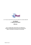
Unit 17 Denmore Industrial Estate, Denmore Road, Bridge of Don, Aberdeen AB23 8JW
User Manual
Telescopic Lubricator
113-2486-HV0
OPS-2486 Rev B
User Manual
Telescopic Lubricator
113-2486-HV0
Table of Contents
Revision History .............................................................................................. iii
Safety.............................................................................................................. iv
1 Introduction ............................................................................................... 1
1.1
General .............................................................................................. 1
1.2
Product Identification ......................................................................... 1
2 Technical Specification ............................................................................. 2
3 Technical Description ............................................................................... 4
3.1
Lubricator........................................................................................... 4
3.2
Collar Safe-Lok .................................................................................. 4
3.2.1
Preparing the Safe-Lok Collar .................................................... 4
3.2.2
Making up the Safe-Lok Collar ................................................... 5
3.2.3
Breaking the Safe-Lok Collar ...................................................... 6
3.3
Test Port Saver Sub .......................................................................... 6
4 Operation .................................................................................................. 7
4.1
Lifting ................................................................................................. 7
4.1.1
Vertical ....................................................................................... 7
4.1.2
Horizontal ................................................................................... 7
4.2
Setting Up Riser (to correct length) ................................................... 7
4.2.1
Vertical Position [Recommended]............................................... 7
4.2.2
Horizontal Position...................................................................... 8
4.3
Making Up the Riser .......................................................................... 8
4.4
Breaking the connection .................................................................... 9
4.5
Replacing the Saver Sub ................................................................... 9
4.6
Pre Job ............................................................................................ 10
4.7
During Job ....................................................................................... 10
4.8
Post Job........................................................................................... 10
5 Maintenance ........................................................................................... 11
5.1
Introduction ...................................................................................... 11
5.2
Schedule.......................................................................................... 11
5.2.1
Pre & Post Job.......................................................................... 11
5.2.2
Yearly ....................................................................................... 11
5.2.3
Five Yearly ............................................................................... 11
5.3
Safety .............................................................................................. 12
5.4
Tools ................................................................................................ 12
5.5
Redress Procedure .......................................................................... 12
5.5.1
Dis-assembly ............................................................................ 12
5.5.2
Assembly .................................................................................. 13
5.6
Maintenance Record Sheet ............................................................. 15
6 Testing .................................................................................................... 16
7 Parts List and Drawings .......................................................................... 17
8 Spares .................................................................................................... 19
8.1.1
Individual Items......................................................................... 19
8.1.2
Supporting Equipment .............................................................. 19
OPS-2486 Rev B
i
User Manual
Telescopic Lubricator
113-2486-HV0
Table 1:Technical Data .................................................................................... 2
Table 2: Setting Up Guide ................................................................................ 3
Table 3: Maintenance Record ........................................................................ 15
Table 4: Parts List .......................................................................................... 17
Table 5 : Redress Kit Part No RDK-2486-HV0 .............................................. 19
Table 6 : Supporting Equipment..................................................................... 19
Figure 1: Lubricator Safety .............................................................................. iv
Figure 2: Telescopic Lubricator Retracted ....................................................... 2
Figure 3: Telescopic Lubricator Extended ........................................................ 3
Figure 4 : NPT Saver Sub ................................................................................ 6
Figure 5: Telescopic Lubricator Assembly ..................................................... 18
OPS-2486 Rev B
ii
User Manual
Telescopic Lubricator
113-2486-HV0
Revision History
Issue, Release Date
Rev A, 10 Feb 09
Rev B, 16 Oct 09
OPS-2486 Rev B
Description
Initial Issue
Change of direction for Dog Nut
operation
iii
User Manual
Telescopic Lubricator
113-2486-HV0
Safety
WARNING: Trapped air requires considerable time to compress and
when it is compressed is highly dangerous. It has enough stored
energy to separate parts with considerable force.
All pressure equipment has a particular pressure rating and care must be
taken to ensure that no item is used in a situation that may cause its working
pressure to be exceeded.
All personnel involved in pressure testing must be formally trained, competent
and utilising the appropriate PPE.
Never attempt to retract the dogs unless the weight of the Housing is safely
supported
Ensure the identification band/plate is fitted and is displaying the correct
information as per the Tag Sheet/Index
This equipment and the equipment it is attached to is heavy never position
yourself below a suspended load
Finger, Glove and
loose clothing trap
area
Care to be taken to
avoid trapping fingers,
gloves and loose
clothing during stabbing
procedure
Figure 1: Lubricator Safety
OPS-2486 Rev B
iv
User Manual
Telescopic Lubricator
113-2486-HV0
1 Introduction
1.1 General
The Phuel Telescopic Lubricator is designed to be used when a non standard
lubricator is required or when lubricators of differing lengths are required for
multiple jobs.
This user manual serves as an introduction to the equipment and contains the
relevant specifications, operation, planning and maintenance instructions,
parts list and drawings.
1.2 Product Identification
Phuel products are identified by a unique serial number that facilitates full
product traceability. Each product is supplied with a documentation pack that
contains product certification and material/inspection reports. The serial
number is always etched on the surface of the product but can sometimes be
difficult to find or read after painting. A customer identification number is also
included to allow the customer to track the asset in their system.
A stainless steel band secures the nameplate tag that is stamped with the
information shown below. This tag should be located in the first instance to
ensure that this manual refers to the correct equipment.
PHUEL OIL TOOLS LTD
DESCRIPTION & SIZE
CUSTOMER ID No
PHUEL ID No 06-XXX-XX
MWP & SERVICE
TEST DATE
OPS-2486 Rev B
1
User Manual
Telescopic Lubricator
113-2486-HV0
2 Technical Specification
Part Number
Connection
Maximum Working Pressure (MWP)
Design Test Pressure
Service
Weight
Overall Length
Make up Length
Inner Diameter
113-2486-HV0
9 – 4 Otis Type Connection
½’’NPT
10,000 Psi
15,000 Psi
H2S
983lbs/445.88kg
Fully Retracted
Fully Extended
75.37”/1.91m
111.41”/2.83m
71.78”/1.82m
107.82”/2.74m
5.13”/0.13m
Table 1:Technical Data
Figure 2: Telescopic Lubricator Retracted
OPS-2486 Rev B
2
User Manual
Telescopic Lubricator
113-2486-HV0
Figure 3: Telescopic Lubricator Extended
Align Groove
0
1
2
3
4
5
6
7
8
9
10
11
Set Groove
1
2
3
4
5
6
7
8
9
10
11
12
MUL (m)
1.900
1.976
2.052
2.129
2.205
2.281
2.357
2.433
2.510
2.586
2.662
2.738
OAL (m)
1.990
2.066
2.142
2.219
2.295
2.371
2.447
2.523
2.600
2.676
2.752
2.828
Table 2: Setting Up Guide
OPS-2486 Rev B
3
User Manual
Telescopic Lubricator
113-2486-HV0
3 Technical Description
3.1 Lubricator
3.2 Collar Safe-Lok
The safe collar lock is designed to provide safe handling of the union collars.
In addition it can be used to prevent accidental back off of the collar. The
following shows the sequence for correct operation.
3.2.1 Preparing the Safe-Lok Collar
After removing the thread protector
the collar will be set in the lower
position and must be moved to the
high position before making up the
connection.
With both hands raise the collar
ensuring the Stop Pins go through the
gaps in the raised rim
Rotate the collar through 90° and
gently lower onto the raised rim.
Ensure collar rests into the grooved
area
OPS-2486 Rev B
4
User Manual
Telescopic Lubricator
113-2486-HV0
3.2.2 Making up the Safe-Lok Collar
Lift and stab the pin into the mating
box and check that there are no signs
of damage to the o-ring (caused by
being misaligned while stabbing in).
With both hands raise the collar clear
of the grooved area on the raised rim
and rotate through 90°. Lower the
collar until it reaches the top of the
threads. Turn the collar anticlockwise
until the start of the thread is found
and then start turning clockwise to
make up the collar to the box thread.
When almost made up fully release
the plungers from the locked open
position.
Tighten the collar down.
OPS-2486 Rev B
5
User Manual
Telescopic Lubricator
113-2486-HV0
3.2.3 Breaking the Safe-Lok Collar
Unscrew the collar completely
Lift the collar up, ensure the stop pins
go through the gaps in the raised rim.
Rotate the collar 90° and lower gently
so that the pins rest in the grooved
portion of the raised rim.
The connection can now be
separated without any risk of
dropping the collar.
3.3 Test Port Saver Sub
The saver sub provides the ability to change a damaged pressure fitting
without repairing or replacing a major component. The saver sub is held in
place by two socket head cap screws and is sealed by means of an o-ring.
The Saver sub can be replaced with a blank version to avoid the need to fit a
pressure blanking plug that would otherwise protrude from Riser assembly.
NPT Saver Sub
Figure 4 : NPT Saver Sub
OPS-2486 Rev B
6
User Manual
Telescopic Lubricator
113-2486-HV0
4 Operation
All operations to be carried out by suitably qualified and competent
personnel
4.1 Lifting
Thread protectors should always be fitted when lifting or moving the riser.
4.1.1 Vertical
The Riser should be lifted with a suitable lifting clamp or cap that is rated for
the total lifting load. (Follow the operating procedures for the clamp or cap
being used.)
If practical leave the thread protectors fitted until ready to make up the
connections.
4.1.2 Horizontal
Suitable slings can be wrapped around either end of the riser to allow
horizontal lifting for means of transportation or fitting. Always pay attention to
the centre of gravity and do not continue to lift if the lubricator is not sitting
horizontal as it might slip through the slings.
4.2 Setting Up Riser (to correct length)
4.2.1 Vertical Position [Recommended]
•
•
•
•
•
•
Set up the Lubricator in a vertical position secured to a test stump with
a lift cap attached to the top thread
Take the weight of the Outer Housing – there is some play within the
grooves so it is possible to see when the weight is taken by the crane
by moving slowly up and down – stop in the mid travel position.
Unscrew the Locking Ring (9) 1-1/4 to 1-1/2 full turns – It is important
that it is within this as this item is used to align the groove later
Remove each of the dogs by turning the Dog Nut (12) anticlockwise. It
is common for the driver to be a little stuck at first and the box spanner
can be used to dislodge the mechanism. DO NOT FORCE THE
DRIVER as this can cause the roll pin to shear. If the dogs cannot be
moved by hand then it is likely that the weight is still on the dogs.
Adjust the crane until all dogs can be fully retracted by hand.
Lift the crane (or lower) to the desired position (see Table above)
The lower face of the Locking Ring should be used to help position the
dogs correctly. Adjust the crane until the face is level with the lower
OPS-2486 Rev B
7
User Manual
Telescopic Lubricator
113-2486-HV0
•
•
•
edge of the groove below where you want to set the dogs (see Table 2:
Setting Up Guide.
Engage the dogs by turning the Dog Nut (12) clockwise. Make sure that
all four fully engage by hand – if they become stuck then it is an
indication that the position is not correct – adjust accordingly until it is
possible to make up all four dogs. The Dog Driver pin should now be
flush with the Nut (12)
Make up the Locking Ring (9) again and ensure that it makes up fully
with the Dog Housing (3)
The position is now set and the weight can now be relaxed from the
crane.
4.2.2 Horizontal Position
•
•
•
•
•
•
•
•
Set up the Lubricator in a horizontal position with the Housing fixed in a
vice and the weight of the Union Mandrel supported with roller stands.
Unscrew the Locking Ring (9) 1-1/4 to 1-1/2 full turns – It is important
that it is within this as this item is used to align the groove later
Remove each of the dogs by turning the Dog Nut (12) anticlockwise. It
is common for the driver to be a little stuck at first and the box spanner
can be used to dislodge the mechanism. DO NOT FORCE THE
DRIVER as this can cause the roll pin to shear. If the dogs cannot be
moved by hand then it is likely that the weight is still on the dogs.
Adjust the stroke of the Mandrel by knocking on the end with a hammer
until all dogs can be fully retracted by hand.
Stroke out to the desire position using a rotation and sideways
movement with the pipe wrench until the desired stroke is achieved.
The lower face of the Locking Ring should be used to help position the
dogs correctly. Adjust the stroke until the face is level with the lower
edge of the groove below where you want to set the dogs (see Table 2:
Setting Up Guide.
Engage the dogs by turning the Dog Nut (12) clockwise. Make sure that
all four fully engage by hand – if they become stuck then it is an
indication that the position is not correct – adjust accordingly until it is
possible to make up all four dogs. The Dog Driver pin should now be
flush with the Nut (12)
Make up the Locking Ring (9) again and ensure that it makes up fully
with the Dog Housing (3)
The position is now set and the Lubricator is ready to use.
4.3 Making Up the Riser
•
•
With the riser hanging vertically above the mating connection, remove
the thread protectors of both ends.
Set the Safe-lok collar to the high position ready for stabbing in.
OPS-2486 Rev B
8
User Manual
Telescopic Lubricator
113-2486-HV0
•
•
•
•
•
Inspect the o-ring for any signs of damage and apply grease if required
Inspect the mating bore and thread for any signs of damage or debris
and clean and grease if necessary
Lower the connection and centralise to ensure that the o-ring is not
loaded on one side. Ensure that the connection has stabbed fully home
and that there are no signs of o-ring debris.
Release the Safe-lok collar and make up the threads until the Safe-lok
engages in the lower groove.
Store the thread protectors in a safe place for use later.
4.4 Breaking the connection
•
•
•
•
•
•
Ensure that all pressure is bled off. The free movement of the collar is
an indication of this.
Unscrew the collar fully
Lift the collar and ensure the Stop Pins pass through the gaps in the
raised rim rotate the collar 90° and lower gently into the grooved area
of the rim. Release the weight of the collar and ensure that it is
supported correctly.
Lift up the riser to break the connection. Visually inspect the o-ring and
male end to make sure that no damage has occurred. Report if
necessary.
Fit the thread protector to the bottom of the riser at this time to prevent
damage when moving. To do this the Safe-Lok collar must be set to the
low position. Take care to support the weight of the collar before
releasing the plungers.
Fit the thread protector to the other thread unless a lifting cap is being
used.
4.5 Replacing the Saver Sub
It is not expected that the save sub would need to be replaced during normal
operations but if damage occurs to a pressure fitting or a leak is found during
pressure testing then this procedure should be followed.
•
•
•
•
•
Ensure that the pressure is bled off.
Do not remove the pressure fittings at this time as they can be used to
provide grip to remove the plug.
Remove the two socket head cap screws and lock washers. (If they
appear unusually tight or difficult to move re-check that the pressure
has been removed).
Grip the pressure fitting and pull out the saver sub with a pulling and
rocking motion. If the pressure fitting has been removed already then
two ¼-20 UNC screws (not supplied) can be used to jack out the sub.
Inspect the o-ring for signs of damage and replace if necessary
OPS-2486 Rev B
9
User Manual
Telescopic Lubricator
113-2486-HV0
•
•
•
•
•
•
Inspect the seal bore for signs of damage and report if necessary
If required, remove the pressure fitting – clean and inspect the pressure
port.
To re-fit the sub, first apply grease to the o-ring and seal bore.
Push the sub into the bore by hand as far as possible, ensuring that the
part is centralised in the bore.
Fit the screws and washers and tighten to drive the o-ring into the bore.
Make up each screw equally to ensure that the sub does not become
twisted.
Fully tighten the screws.
4.6 Pre Job
•
•
•
•
•
•
•
•
•
•
•
Ensure thread protectors are fitted
Check maintenance record sheet and ensure the equipment has been
maintained by competent personnel
Check all certification is in date
Confirm information band is fitted and correct
Ensure equipment is suitable for the maximum working pressures and
services involved
Ensure ‘O’ ring (27) is seated correctly and there are no signs of
damage
Ensure threads are clean
Inspect for signs of damage
Pressure test to maximum working pressure
Carry out a collar lock test and ensure correct operation
Ensure all connections are tight and that the test port is tightly fitted
4.7 During Job
•
•
Ensure collar lock has operated correctly and the collar is locked in
position
Avoid excessive movement
4.8 Post Job
•
•
•
•
•
Inspect for signs of damage
Ensure threads are clean
Ensure thread protectors are fitted
Ensure that any exposed grooves on the Union Mandrel (2) are well
lubricated with grease
If practical fully extend the Lubricator – clean and grease all the
grooves and the lower and set in the lowest position.
OPS-2486 Rev B
10
User Manual
Telescopic Lubricator
113-2486-HV0
5 Maintenance
All maintenance to be carried out by suitably qualified and competent
personnel
5.1 Introduction
Regular maintenance of the equipment using Phuel redress kits or Phuel
approved parts is essential to its continued safe operation. Ensure that the pre
and post job operating procedures are followed and that maintenance records
are kept.
5.2 Schedule
The maintenance schedule may be governed by international or company
standards and the following is considered to be the minimum requirements.
5.2.1 Pre & Post Job
Refer to Section 4.6 and Section 4.8 for details
5.2.2 Yearly
•
•
•
•
•
•
•
•
Disassemble Lubricator (see section 5.5.1) clean and degrease all
components
Inspect the condition of all sealing surfaces and surface coatings
Re-coat threads and sealing surfaces if necessary. If in doubt contact
Phuel Oil Tools Ltd
Replace all elastomeric seals with items from redress kit (Table 5)
Regrease components
Re-assemble (see section 5.5.2)
Pressure test to maximum working pressure in accordance to testing
procedure (see section 6)
Inspect paint work and repair as necessary
5.2.3 Five Yearly
•
•
•
Yearly Maintenance (plus the following)
Carry out surface NDE on all component threads and damaged
surfaces
Pressure test to maximum working pressure (witnessed by certifying
authority where applicable)
OPS-2486 Rev B
11
User Manual
Telescopic Lubricator
113-2486-HV0
5.3 Safety
•
•
•
•
•
•
Many of the components are heavy and should not be lifted without
lifting aids.
Ensure all pressure testing is carried out in the appropriate testing area
by suitably qualified personnel.
Wear appropriate personal protective equipment.
Do not over exert yourself while using torque wrenches. Use
appropriate mechanical advantages when available.
Ensure that all tools and equipment are in good condition and are
suitable for the intended use.
Clear up any fluid spills immediately to avoid slips.
5.4 Tools
The following tools/equipment is required:
• Test Stump
• Lift/Test Cap
• Crane or other suitable lifting device
• Pipe wrench suitable for 10.5” diameter (non marking preferred)
• 24mm Box Spanner
• 3/8 Hex Key
5.5 Redress Procedure
5.5.1 Dis-assembly
• Attach Lift Cap to Top Sub (4) and support with crane. Back up on the
Outer Housing (1) and then turn the Dog Housing (3) to break the
connection - while making height adjustments with the crane to support
the weight. When free lift the Outer Housing off the Union Mandel (2)
• Remove the top sub (4) from the Outer Housing (1)
• Remove Scrapers (15) and T-Seals (16) from the Union Mandel (2)
• Remove Bottom Sub (5) from Union Mandel (2)
• Remove Save Sub Port (10) from Bottom Sub (5) and remove the ORing (24)
• Remove Stop Pins (19) and washers (20) from collar, remove the Split
Ring (7) and remove collar from the Bottom Sub (5)
• Mount the Union Mandrel horizontally in a vice and remove the Locking
Ring (9) and screw out Dogs (8) by turning the Drive Nut (12)
clockwise. Slide Dog Housing (3) off Union Mandel (2)
• From each of the 4 holes on the dog housing remove the Circlip (18)
then extract the Spacer (11) and Thrust Bearing assembly(17) by
unscrewing the Drive Nut (12) from the Dog Driver (13)
OPS-2486 Rev B
12
User Manual
Telescopic Lubricator
113-2486-HV0
• Extract the Dog (8) and Dog Driver (13) from inside the Dog Housing
(3) then remove the remaining Thrust Bearing assembly (17) and
Debris Washer (14)
• If necessary, carefully remove the Roll Pin (29) from each of the Dogs
(8) and separate the Dogs (8) from the Dog Driver (13)
• Remove and Discard all Elastomers
5.5.2 Assembly
5.5.2.1 Dog Housing Sub-Assembly
• Align the hole at the bottom of the Dog Driver (13) with hole of the Dog
(8).
• Carefully knock in Roll Pin (29) through both holes, ensure that the end
of the pin is flush with the Dog (8). Repeat for the other three Dogs (8).
• Position all four Dogs (8) with assembled Dog Drivers (13) in the Dog
Housing (3), directing the ends of the Dog Driver (13) though the holes.
• Insert Thrust Bearing (17) and Debris Washer (14) into the hole,
around the Dog Driver (13).
• Screw the Drive Nut (12) onto the Dog Driver (13), and then place
Thrust Bearing (17) around the Drive Nut (12).
• Assemble O-Ring (22) and (23) to Spacer (11), and then push into the
hole, around Drive Nut (12).
• Insert Circlip (18) into groove.
• Repeat steps four to seven with the remaining three holes.
• Turn Drive Nut (12) clockwise to retract the Dogs (8), and then
assemble Locking Ring (9), DO NOT TIGHTEN
• Sub-assembly is complete, set to one side.
5.5.2.2 Bottom Sub Assembly
• Slide Collar (6) over Bottom Sub (5), and then assemble Split Ring (7)
to Collar (6) until flush – back off to align the holes
• Insert Stop Pins (19) and Washers (20) into Collar (6) and Split Ring (7)
• Insert O-Ring (24) to Saver Sub Port (10).
• Insert Saver Sub Port (10) into Bottom Sub (5) with Socket Head Cap
Screw (21) and washers (20).
• Assemble O-Ring (27) to Bottom Sub (5) and lightly grease.
• Sub-assembly is complete, set to one side.
5.5.2.3 Final Assembly
• Slide Dog Housing (3) over the Union Mandel (2) with the Locking Ring
(9) at the bottom.
OPS-2486 Rev B
13
User Manual
Telescopic Lubricator
113-2486-HV0
• Align the bottom face of the Locking Ring with the lower edge of the
lowermost groove (a higher setting can be used if required). Screw the
Dogs (8) into the groove up by turning the Drive Nut (12) anticlockwise, and then tighten Locking Ring (9) fully to lock the dogs. Do
not force the dogs at this point – it should be possible to drive the dogs
by hand – if more force is required the reposition the dog housing.
• Insert O-Ring (26) to Phuel thread end of Union Mandel (2) and lightly
grease.
• Make up the Bottom Sub (5) to the Inner Mandrel and tighten with pipe
wrench to activate metal seal.
• Ensure that the collar is set in the upper lock position. Lift the Union
Mandrel from the vice and stab into the test stump – make up the collar
• Insert T-Seals + Back-ups (16) and Scrapers (15) to other end of Union
Mandel (2) and lightly grease. Ensure that the sharp edge of the lower
scraper is at the bottom and the edge of the upper one is at the top.
• Insert O-Ring (26) to Outer Housing (1) and lightly grease.
• Assemble Top Sub (4) to Outer Housing (1). Make up with a pipe
wrench to activate the metal seal
• Attach the Lift Cap into Top Sub (4) and lift with Forklift / Crane
• Allow the Outer Housing (1) to slide over Union Mandel (2), once
thread reaches Dog Housing (3), turn the Dog Housing (3) to make up
the thread whilst gradually lowering the Forklift / Crane.
• Assembly complete. Refer to Operation section for details on how to
set to the desired height.
OPS-2486 Rev B
14
User Manual
Telescopic Lubricator
113-2486-HV0
5.6 Maintenance Record Sheet
Date
Type of
Performed
Performed Maintenance
By
Verified
By
Comments
Table 3: Maintenance Record
OPS-2486 Rev B
15
User Manual
Telescopic Lubricator
113-2486-HV0
6 Testing
All testing is to be carried out in the designated test area and by suitably
qualified and competent personnel.
WARNING: Trapped air requires considerable time to compress and
when it is compressed is highly dangerous. It has enough stored
energy to separate parts with considerable force.
•
•
•
•
•
•
•
•
Fit appropriate test caps and blanking plugs
Fill with testing fluid bleeding off any air within the system
Apply a pressure of 500 psi and ensure pressure holds for a minimum
of 10 minutes
Increase pressure to 10,000 psi (Maximum Working Pressure), allow to
stabilise and maintain this pressure until it is evident there are no
apparent leaks.
Bleed off pressure, drain test fluid and dry
Remove test caps
Apply coating of de-watering solution to protect the bore and threads
Fit thread protectors
On completion of all maintenance ensure the maintenance record sheet (Para
5.6) is completed
OPS-2486 Rev B
16
User Manual
Telescopic Lubricator
113-2486-HV0
7 Parts List and Drawings
Item Number
1
2
3
4
5
6
7
8
9
10
11
12
13
14
15
16
17
18
19
20
21
22
23
24
25
26
27
28
29
100
101
Part Number
113-2444-480
113-2468-480
113-2465-480
113-2466-480
110-2289-480
110-2053-480
110-2054-480
113-2463-480
113-2464-480
145-2176-480
113-2489-N66
113-2469-PLA
113-2470-STL
113-2490-PU8
113-2467-PEK
802-2471-V80
113-2487-STL
113-2503-STL
110-2329-3A4
WNL-0580-STL
SHC-0583-3A4
801-0024-V90
801-0031-V90
801-0119-V90
801-0361-V90
801-0369-V90
801-0438-V90
113-2488-STL
113-2545-STL
910-2155-N66
910-2156-N66
Quantity
1
1
1
1
1
1
1
1
1
1
4
4
4
4
2
2
8
16
4
6
2
4
4
1
1
2
1
4
4
1
1
Description
OUTER HOUSING (7.25" BORE)
UNION MANDEL
DOG HOUSING
TOP SUB
BOTTOM SUB
COLLAR 9-4 (SPLIT TYPE)
SPLIT RING (9-4)
DOGS
LOCKING RING
SAVER SUB PORT
SPACER
DRIVE NUT
DOG DRIVER
DEBRIS WASHER
SCRAPER
PISTON T-SEAL (7.250 BORE)
THRUST BEARING (INA-535 - TC2031)
BEARING WASHER (INA-535 - TWA2031)
STOP PIN
Nord Lock Washer (M12)
Soc Hd Cap Size 1/2 Length 0.75 in
O-Ring - B.S Size 024
O-Ring - B.S Size 031
O-Ring - B.S Size 119
O-Ring - B.S Size 361
O-Ring - B.S Size 369
O-Ring - B.S Size 438
CIRCLIP (DHO-50)
ROLL PIN (SPLIT) 1/8 X 1." LONG
9-4 ACME MALE PROTECTOR
9-4 ACME FEMALE PROTECTOR
Table 4: Parts List
Note: Thread Protectors (item100 and 101) not shown in assembly drawing
Figure 5
OPS-2486 Rev B
17
User Manual
Telescopic Lubricator
113-2486-HV0
Figure 5: Telescopic Lubricator Assembly
OPS-2486 Rev B
18
User Manual
Telescopic Lubricator
113-2486-HV0
8 Spares
Use only spares supplied or approved by Phuel Oil Tools Ltd.
It is recommended that sufficient quantities of the following spares be
maintained to ensure that the equipment is always available when required.
Elastomeric spares are supplied in Viton material as standard. Many other
materials are available please specify when ordering.
Part No
Qty
801-0024-V90
801-0031-V90
801-0119-V90
801-0361-V90
801-0369-V90
801-0438-V90
802-2471-V80
4
4
1
1
2
1
2
Description
Comments
O-Ring - B.S Size 024
O-Ring - B.S Size 031
O-Ring - B.S Size 119
O-Ring - B.S Size 361
O-Ring - B.S Size 369
O-Ring - B.S Size 438
PISTON T-SEAL (7.250 BORE)
Table 5 : Redress Kit Part No RDK-2486-HV0
8.1.1 Individual Items
Individual items may be ordered as required using the part number specified
Note: O-Rings conform to industry standards and may be substituted with
those from other suppliers -– at the sole risk of the user.
8.1.2 Supporting Equipment
The following test fixtures are available for order directly from Phuel Oil Tools
Ltd
Part No.
205-2105-480
111-2493-HV0
Item Description
Blank Test Sub
Lubricator Manifold Valve
Comments
Table 6 : Supporting Equipment
OPS-2486 Rev B
19