1
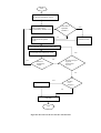
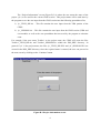
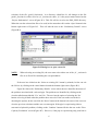
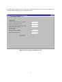
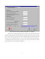
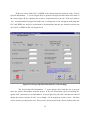
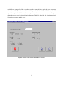
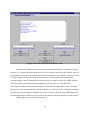
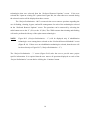
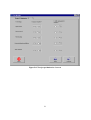
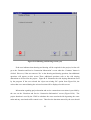
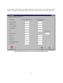
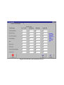
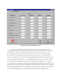
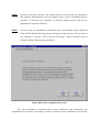
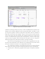
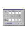
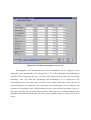
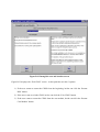
APPENDIX B - USER INTERFACE WITH THE CDSS The software for the Comprehensive Decision Support System (CDSS) is written in Microsoft® Visual Basic 6.0 and runs in the Windows 95 /98 environment. It also requires the use of Microsoft® Excel, preferably Excel 97. The PC should have a Pentium 100 MHz processor, or better, and a minimum of 32 MB RAM for efficient processing. The software by itself occupies approximately 4 MB of space on the hard drive. Familiarity with Microsoft® Excel is assumed in the design of this software package. User friendly screens facilitate data entry, analysis and output. The user should familiarize him/herself with the details given in this user manual before attempting to execute of the software. Components Microsoft® Visual Basic 6.0 has been used to create the Graphical User Interface for this software package. This works as the front-end of the program and provides the interface between the user and the cost spreadsheet program. The cost spreadsheet program is a Microsoft® Excel file, which is used for data storage and computation. Installation The CDSS is distributed along with a user-friendly SETUP program that aids in the installation of the software. Upon executing the SETUP program, the user will be prompted for the selection of an appropriate folder (directory) for the installation. Within this user specified installation directory, a subdirectory named DSS_PIPE, will be created with the files necessary to run the program. These files include: 1) DSS.exe - the executable file to run the CDSS 2) cost.xls – a cost spreadsheet which stores data for cost computation and analysis 3) water.xls - a template file used to generate the output for the technology selection module (TSM) The presence of the above files implies successful installation and the user can proceed with the execution of the software. NOTE: Because the original cost spreadsheet (cost.xls) will be modified by the CDSS upon execution of the program, the user is advised to make a backup copy of the ‘cost.xls’ 1 file into a directory different from the installation directory, prior to running the program. Running the CDSS Double clicking on the “water – tap” icon in the DSS_PIPE directory, initiates the CDSS. Figure B.1 shows the first screen that appears in the program. Clicking on the ‘START’ button starts the program. When the user starts the program he/she will first go through the TSM portion of the CDSS, which selects the appropriate renewal technologies for the project based on pipe and site specific information provided by the user. Once the appropriate renewal technologies have been selected, the user can utilize the cost module portion of the CDSS to perform present worth cost analysis of each selected technology to assist in the final selection process. Figure B.2 provides a flow chart of the user interface with the TSM portion of the CDSS. Figure B.1 Start screen 2 Start Enter Project Name (fn) on Project Information screen Identify type of problem pipe is experiencing on Preliminary Details screen Structural or Hydraulic Problem ? Yes No Display Renewal Options on the Renewal Options screen Flow Capacity Evaluation Screen Project Specific Information screens 1 & 2 Yes Preferred Renewal Methods screen Yes No Return to Project Specific Information Screen? Return to Preliminary Details No Yes Perform Cost Analysis? Cost Module No Exit DSS End Figure B.2 Flow chart of the user interface with the TSM 3 The “Project Information” screen (Figure B.3) is where the user enters the name of the project (‘fn’) to be used for the current CDSS session. This project name will be used later by the program to save the user input from the CDSS session into the following spreadsheet files: 1) ‘fn’_TECH_INP.xls – This file contains the user input from the TSM portion of the CDSS. 2) ‘fn’_SESSION.xls. – This file contains the user input from the CDSS session (TSM and cost module) as well as the cost spreadsheet that was used by the program to calculate costs. For example if the user enters TestNo.1 as the project name, the CDSS will create the files TestNo.1_TECH_INP.xls and TestNo.1_SESSION.xls within the DSS_PIPE directory. In general if ‘fn’ is the project name, the files ‘fn’_TECH_INP.XLS and ‘fn’_SESSION.XLS are created in the DSS_PIPE directory. Once the required name is entered, the user can proceed to the next screen by clicking on the ‘Continue’ button. Figure B.3 Project information screen 4 The “Selection of Cost Spreadsheet” screen (Figure B.4) is where the CDSS is instructed on which cost spreadsheet to use. If the user selects the ‘Start a new session’ option, the user input from the CDSS session will be written to the ‘cost.xls’ cost spreadsheet by default and the user will be taken to the next screen. NOTE: First time users must select the ‘Start a new session’ option. Figure B.4 Selection of cost spreadsheet screen However, if the user has previously completed a CDSS session (which has been saved as ‘fn’_Session.xls) he/she can select the ‘Open an existing file’ option and select the appropriate file to be used by the CDSS. By selecting this option, many of the user inputs provided during the previous session will automatically be displayed by the CDSS. Upon selecting the ‘Open an existing file’ option, the user is led to the file box displaying all of the Microsoft® Excel files in DSS_PIPE directory (see Figure B.5). If the desired file is not in the DSS_PIPE directory, the user should open the appropriate directory and select the file. For example, Figure B.5 shows the 5 selection of the file ‘good1_Session.xls.’ in a directory called Dss-36. All changes to the file good1_Session.xls will be saved as ‘fn’_Session.xls where ‘fn’ is the project name entered on the “Project Information” screen (Figure B.3). This file will be saved to the DSS_PIPE directory. When the user has selected the file to be used, he/she must then click on the ‘Open’ button in the bottom right corner of Figure B.5. This will take the user to the “Preliminary Details” screen (Figure B.6). Figure B.5 Dialog box to open a new file NOTE: When selecting an existing file, the user must select either one of the ‘fn’_session.xls files or an Excel file containing the cost spreadsheet. If the user has clicked on the ‘Select an existing file’ button by mistake, he/she can exit the file box by clicking on the cancel button located the bottom right corner (Figure B.5). Figure B.6 shows the “Preliminary Details” screen where the user identifies the nature of the problem associated with a selected pipe. The problems are identified by clicking on the circular radio buttons labeled ‘Yes’ and ‘No’. The user has the option of selecting the ‘No’ button or leaving it blank when the problem does not exist. If the user makes a mistake in choosing the options, he/she can click the ‘Reset’ button at the bottom left corner of the screen to clear the previous selections and the user can start again. If the pipe is experiencing either a structural or hydraulic problem, clicking on the ‘Continue’ button will take the user to the “Flow Capacity Evaluation” screen (Figure B.7). However, if the pipe is experiencing only joint leak or 6 water quality problems the user is directed to the “Renewal Option Category” screen (Figure B.9). Figure B.6 Preliminary details The “Flow Capacity Evaluation” screen (Figure B.7) allows the user to determine whether the existing pipe and renewed pipe are undersized. The user must provide information about the original pipe (at the time of its original installation as well as in its present condition) and the renewal pipe/liner. Once the required information has been entered, the user must hit the ‘Flow evaluation’ button so that he/she can calculate the percent of original flow capacity for the existing pipe and the percent of original flow capacity for the renewed pipe. An example is provided in Figure B.8. Based on the flow evaluation the user is asked to decide if the pipe is undersized or not. After answering either ‘Yes’ or “No’ to the “Is the pipe undersized?” question, the user can proceed to the “Renewal Option Category” screen which will display the appropriate 7 renewal option categories based on the type of problem indicated by the user and whether the user has determined the pipe to be undersized or not. Figure B.7 Flow capacity evaluation screen 8 Figure B.8 Flow capacity evaluation screen (after flow evaluation) With the pipe problems identified and flow capacity evaluated (for structural and hydraulic problems only) the CDSS will display the applicable renewal option categories (Figure B.9). At this point the user can select the ‘Back to Preliminary Details” option which will take the user back to the “Preliminary Details” screen to modify the information regarding the types of problems associated with the pipe or the ‘Renew Pipe’ option to proceed to the “Project Specific Information” screens (Figures B.10 and B.12). 9 Figure B.9 Renewal option categories screen The “Project Specific Information” screens (Figures B.10 and B.12 respectively) are where the user must provide the pipe and site specific information for the project. The user must select the existing and replacement pipe material by clicking on the correct radio button and also manually enter all of the values in the blank boxes. The ‘Diameter of the New Pipe” must be selected by the user by clicking the down arrow on the adjacent text box. This will show a pull down menu with the available replacement pipe diameters. If the user selected the ‘Open an existing file’ option for the “Selection of Cost Spreadsheet” screen (Figure B.4), then the values that were entered during the selected session will be displayed on this screen, with the exception of the ‘Soil Conditions’. If the user would like to change all of the values that were previously entered, he/she can click on the ‘Reset’ button. To aid the user in selecting the type of ‘Soil Conditions’ applicable to their particular project, Table B.1 is provided. The user should consult the appropriate soil map of the area for proper selection. 10 Figure B.10 Project specific information-1 screen Table B.1 - Soil type by size Soil type Size (millimeters) Hard ground mixed gravel and cobble; hard to drill Clay less than 0.002 Sand 0.05 – 1.0 Source: (U.S. Dept. of Agriculture 1985) The user must enter values for each field on this screen before clicking on the ‘Continue’ button. If the user has left any of the required fields blank and tries to proceed to the next screen, a message will appear asking the user to provide the missing information. 11 If the user selects either PVC or HDPE as the replacement pipe material on the “Project Specific Information – 1” screen (Figure B.10) a question will appear at the bottom left corner of the screen (Figure B.11) regarding the presence of hydrocarbons at the site. If the user answers ‘Yes’ to hydrocarbons being present in the soil, a warning note in red will appear indicating that PVC and HDPE are subject to permeation by hydrocarbons and the user should reevaluate the use of PVC or HDPE at this site (Figure B.11). Figure B.11 Project Specific Information-1 (with warning) The “Project Specific Information – 2” screen (Figure B.12) asks the user to provide more site specific information about the project. If the user selected the ‘Open an existing file’ option at the “Selection of Cost Spreadsheet” screen (Figure B.4), then the value that was entered during the selected session for the ‘Cover Depth’ will be displayed on this screen. All other values must be provided by the user. This screen is also provided with a ‘Reset’ button if the user 12 would like to change all of the values that have been entered. Once again, the user must enter values for each field on this screen before clicking on the ‘Continue’ button. If the user has left any of the required fields blank and tries to proceed to the next screen, a message will appear asking the user to provide the missing information. Table B.2 describes the site characteristic information requested on this screen. Figure B.12 Project specific information–2 screen 13 Table B.2 - Definition site specific information from Figure B.12 Factor Rural Definition Re-paving and extensive traffic management are not needed; work space is not limited Urban Re-paving and traffic management needed Limited work space Insufficient work space available at the ground surface to operate machinery Unrestricted work space Sufficient work space available at the ground surface to operate machinery Major obstructions There are other underground utilities within 3-ft. of the pipe; presence of building foundations in the path of the pipe to be renewed; or underground boulders High water table Groundwater can seep into the trench and/or entrance and exit pits. Cover depth Depth of soil to the top of the pipe. The information from the two project specific information screens is used by the CDSS to select the appropriate renewal technologies using the knowledge base discussed in briefly Section 1.0 of the user’s manual and in more detail in Chapter 5 of the Decision Support System for Distribution Piping Replacement and Rehabilitation Report. The renewal technologies selected by the CDSS are displayed on the “Preferred Renewal Methods” screen (Figure B.13). The renewal technologies are grouped into rehabilitation and replacement technologies. 14 Figure B.13 Preferred renewal methods screen If portions of the pipe to be renewed are considered inaccessible (i.e. highway crossings, streams, etc.), the user should treat the project as two separate scenarios in the CDSS in order for the program to select the most appropriate renewal technologies. For example, a project involves a 500 foot length of pipe to be renewed that crosses a 50 foot stream (in the middle of the renewal length). If the user attempts to treat the project as a single scenario, the CDSS will not select any of the trenched replacement technologies for the project, even though these technologies could be used to replace a majority of the renewal length. While if the user treats the project as two separate scenarios, he/she could have a wide variety of technologies to choose from for the portion of the pipe that does not cross the stream, and at have the CDSS determine the most appropriate technologies to be used for the portion of the pipe that involves the stream. At this stage the user is offered four choices: 15 1) Return to the “Preliminary Details” screen is selected if the user wants to restart the whole selection process. This will take the user back to Figure B.6. 2) Return to the “Project Specific Information – 1” screen is selected if the user wants to modify only pipe and site characteristic information. This will take the user back to Figure B.10. 3) Exit the CDSS is selected if the user does not want to make any changes to the existing session, and does not want to perform the cost analysis. 4) Continue with the cost calculation is selected if the user want to perform a present worth cost analysis on the technologies displayed on this screen. If the CDSS did not select one or more technologies that the user would like to include in the cost analysis, the user can include these technologies by using the pull down menus below the selected rehabilitation and replacement technologies. For example, to add a rehabilitation technology, the user clicks on the down arrow located under the box that displays the selected rehabilitation technologies. This activates a pull down menu showing the list of remaining rehabilitation technologies. The user selects a technology by clicking on it with the mouse and then clicking the ‘Add’ button. This technology will then be displayed in the main ‘Rehabilitation Technologies’ box. In the example shown in Figure B.14 ‘Cathodic protection’, ‘Conventional sliplining’ and ‘Close-fit sliplining’ have been added to the selected rehabilitation technologies. The technologies displayed on the “Preferred Renewal Methods” screen at the time the user clicks on the ‘Perform Cost Analysis’ button, will be the technologies that the model performs a present worth cost analysis for. At this stage of the program all of the user input and the recommended technologies are written to an output file which is named ‘fn’TECH_INP.xls (where ‘fn’ is the project name that the user entered on the “Project Information” screen (Figure B.3) and saved in the DSS_PIPE directory. 16 Figure B.14 Preferred renewal methods screen (with addition of new technologies) Present Worth Cost Analysis The cost module portion of the CDSS asks the user project specific information regarding the technologies that were selected by the TSM. This information, along with the pipe and site characteristic information that was entered by the user in the TSM, is written to a cost spreadsheet that calculates the present worth cost of each selected technology. The cost spreadsheet is either the ‘cost.xls’ file or the spreadsheet selected by the user from Figure B.5. A flow chart of the user interface with the cost module portion of the CDSS is provided in Figure B.16. Once the user has selected ‘Perform Cost Analysis’ option from the “Preferred Renewal Options” screen (Figure B.14), the CDSS will display the “Project Preliminaries” screens (Figures B.15, B.17 and B.18). The program only asks the user to provide information for those 17 technologies that were selected from the “Preferred Renewal Options” screen. If the user selected the “Open an existing file” option from Figure B.4, the values that were entered during the selected session will be displayed on these screens. The “Project Preliminaries –1&2” screens ask the user to answer questions regarding the use of flushing, cleaning, bypass, and traffic management for each of the technologies selected on the “Preferred Renewal Options” screen. The questions can be answered by selecting the radio button next to the ‘Y’ (Yes) or the ‘N’ (No). The CDSS assumes that cleaning and flushing will not be performed with any of the replacement technologies. NOTE: Figure B.15 (“Project Preliminaries – 1”) will be displayed only if rehabilitation technologies were among those selected on the “Preferred Renewal Methods” screen (Figure B.14). If there were no rehabilitation technologies selected, then the user will be taken directly to Figure B.17 (“Project Preliminaries – 2”). The “Project Preliminaries – 3” screen (Figure B.18) asks the user to provide more project specific information. It is required that the user answer all questions displayed on each of the “Project Preliminaries” screens before clicking the ‘Continue’ button. 18 Figure B.15 Cost module - project preliminaries-1 screen 19 Start Technology Selection Module (TSM) Project Preliminary screens1, 2 and 3 Sheeting and Shoring screen Duration Service Connection Information Screen Entrance and Exit Pit Information screens Annual Maintenance Costs screen Change Unit Costs? Yes Edit Cost Spreadsheet No Construction Cost Factors screen Display Raw Costs and Marked up Costs Intangible Costs and Benefits screen Yes No Restart DSS? DSS Inputs and Cost Spreadsheet Written to fn*SESSION.xls Restart Cost Module? Yes No Exit DSS End Figure B.16 Flow chart of the user interface with the cost module 20 Figure B.17 Project preliminaries-2 screen 21 Figure B.18 Project preliminaries-3 screen Once all of the required project preliminary information has been provided by the user, the CDSS will take the user to the “Sheeting and Shoring” screen (Figure B.19). This screen asks the user whether sheeting and shoring will be required for the project. It should be noted that sheeting and shoring will apply to any trenches as well as any entrance and exit pits required for the selected technologies. This information is used by the program to calculate the trench and entrance/exit pit volumes. The CDSS assumes that all trenches and entrance/exit pits are rectangular when viewed from the side (i.e. trench depth does not increase or decrease over the length of the trench). 22 Figure B.19 Sheeting and shoring screen (yes) If the user indicates that sheeting and shoring will be required for the project, he/she will go to the “Duration and Service Connection Information” screen when the ‘Continue’ button is clicked. However, if the user answers ‘No’ to the sheeting and shoring question, four additional questions will appear on this screen These additional questions refer to the side sloping dimensions to be used for the project. Figure B.21 illustrates the side sloping dimensions used by the program. If the user selected the “Open an existing file” option from Figure B.4, the values that were entered during the selected session will be displayed on this screen. Information regarding project duration and service connection excavations is provided by the user on the “Duration and Service Connection Information” screen (Figure B.20). The project duration is used by the CDSS to calculate the costs associated with bypassing the water main and any associated traffic control costs. Therefore the duration entered by the user should 23 be the amount of time that the associated technology will need bypass service and require traffic control. It should be noted that the number of service connection excavations may be less than Figure B.20 Duration and service connection information screen 24 SW A D A SW SD A= B= C= D= SD = C No. of inches to be excavated on either side of the pipe. No. of inches to be excavated below the pipe. No. of inches to be excavated above the pipe before side sloping begins. Pipe diameter of existing pipe. For open trench = Cover depth (to top of pipe) - C D For entrance/exit pits = Pit depth - (B + C + D) SD * Slope SW = = 0 when sheeting and shoring will be used Slope = Horizontal run (SW) / vertical rise (SD) D B Figure B.21 Side sloping dimensions used in CDSS to calculate trench volumes 25 the number of service connection valves if any of the service connection pits can be shared between valves, or if any of the service connections can be accessed through the entrance or exit pits. The program only asks the user to provide information for those technologies that were selected on the “Preferred Renewal Options” screen (Figure B.14). If the user selected the “Open an existing file” option from Figure B.4, the values that were entered during the selected session will be displayed on this screen. The user must ensure that all of the requested information has been provided before clicking the ‘Continue’ button to proceed to the next screen. Information about the entrance and exit pits is provided by the user on the “Entrance Pit Information” and “Exit Pit Information” screens (Figures B.22 and B.23). The user is only required to provide information for those technologies that were selected on the “Preferred Renewal Options” screen (Figure B.14). If the user selected the “Open an existing file” option from Figure B.4, the values that were entered during the selected session will be displayed on these screens. The user must ensure that all of the requested information has been provided before clicking the ‘Continue’ button to proceed to the next screen. Figure B.22 Entrance pit information screen Figure B.23 Exit pit information screen In order to perform the present worth cost analysis, the user is asked to provide the following information for each applicable pipe/liner material: the initial number of years when no maintenance costs are expected, the number of years where maintenance costs will be incurred, and the expected uniform annual maintenance costs on the “Annual Maintenance Costs” screen (Figure B.24). On this screen, the replacement pipe material selected by the user on the “Project Specific Information – 1” screen (Figure B.10) will be used as the pipe material for all replacement technologies selected on the “Preferred Renewal Options” screen (Figure B.14), while the user must enter values for each rehabilitation technology that was selected. For example, Figure B.14 displays Close-fit sliplining, Cathodic protection, Open trench, Horizontal directional drilling and Jack and bore as the preferred renewal options. Therefore, the user must enter the annual maintenance cost values for DI (selected by the user on Figure B.10). NOTE: The annual maintenance costs associated with cathodic protection are for the maintenance associated with the anodes, not the host pipe. The user must ensure that all of the requested information has been provided before clicking the ‘Continue’ button to proceed to the next screen. Figure B.24 Annual maintenance costs screen The “Unit Cost Modification” screen (Figure B.25) is where the user indicates whether he/she would like to modify the cost spreadsheet. This will open the Microsoft® Excel program and open the cost spreadsheet specified by the user on the “Selection of Cost Spreadsheet” screen. If the user selects the ‘Start a new session’ option on this screen, the CDSS selects the ‘cost.xls’ cost spreadsheet by default. However, if the user selects the ‘Open an existing file’ option on this screen, the cost spreadsheet that was selected by the user will be edited. NOTE: First time users must select the ‘Yes’ button on this screen since unit cost information and ‘quantity’ information for each cost category in the ‘cost.xls’ spreadsheet must be provided. To assist the user, Appendix A contains a sample scenario with the cost spreadsheets completely filled out. NOTE: As soon as the cost spreadsheet is opened the unit cost worksheet will be displayed (Figure B.28) and the following message will pop up while in Excel: “Do you want to save changes to ‘cost.xls’?” The user must click on the ‘Cancel’ button in order to continue making changes to the spreadsheet. Figure B.25 Unit cost modification screen The cost spreadsheet is organized into several worksheets, each performing cost computations for a specific cost category. Section 1 provides a brief explanation of each of the worksheets contained in the cost spreadsheet. Once the unit cost information has been entered, the user can proceed to the next worksheet by clicking on the tab at the bottom of the screen to modify cost category information. For each cost category, assumptions were made regarding the types of direct costs, i.e., the equipment, labor, operating, material and disposal costs that will be associated with each category. Some of the “quantity” values are calculated by the spreadsheet using input data provided by the user during the CDSS session, these cells have been highlighted purple and protected in the Figure B.26 Unit cost worksheet Figure B.27 Open trench cost details worksheet worksheet to avoid being written over by the user. If there are additional direct costs that are not displayed on the worksheet, additional rows have been provided (Other 1 and Other 2) so the user can enter the “quantity” (Column C in Figure B.27) value and the “unit cost” (Column E in Figure B.29) value directly on the worksheet. However, if the user does not wish to break the costs for each category down into such detail, each worksheet provides the user with the option to enter a “User Entered Total Cost Value” (Row 26 on Figure B.27). If the user wishes to enter a total cost value, the “quantity” fields for all other direct costs must be set to zero. Figure B.27 displays and example of the ‘Open trench cost details’ cost category worksheet. Once all of the necessary changes have been made to the cost spreadsheet the user must save the file and exit Microsoft® Excel. When the user exits Microsoft® Excel, he/she is taken back to the “Construction Cost Factors” screen (Figure B.28) in the CDSS. The “Construction Cost Factors” screen (Figure B.28) asks the user to enter the following factors which will be used by the CDSS to calculate total marked up costs for each technology. Contractor profit – influenced by geographic location, degree of competition, and project size Project oversight - refers to the cost of field supervision and project management activities. Engineering design and support – influenced by project complexity, project size, and engineering services to be provided Legal and administrative fees – influenced by permitting difficulties, land acquisition requirements, outside legal services requirements Contingency – influenced by uncertainties in project definition and level of cost estimate The user will only be required to provide cost information for those technologies that were selected on the “Preferred Renewal Options” screen (Figure B.14). If the user selected the “Open an existing file” option from Figure B.4, the values that were entered during the selected session will be displayed on this screen. The user must ensure that all of the requested information has been provided before clicking the ‘Continue’ button to proceed to the next screen. Figure B.28 Construction cost factors screen To compute the raw costs, the user must click on the ‘Compute raw costs’ button on the “Cost Computation” sheet (Figure B.29). This allows the raw and marked up costs to be computed based on all of the user inputs and displayed on the “Calculated Raw Costs” screen (Figure B.30) and the “Marked up Costs” screen (Figure B.31). Only the costs for those technologies that were selected on the “Preferred Renewal Options” screen (Figure B.14) will be displayed on Figures B.30 and B.31. NOTE: The costs displayed in Figures B.30 and B.31 should not be considered actual costs but should be treated as comparative costs only. They are not a substitute for a detailed contractor’s bid for constriction. For actual costs, the user should contact a local contractor. Figure B.29 Cost computation screen Figure B.30 Calculated raw costs screen Figure B.31 Calculated marked up costs screen The intangible costs and benefits for selected technologies can be displayed on the “Intangible Costs and Benefits” screen (Figure B.32). To see the advantages and disadvantages associated with a technology, the user can click on the pull down menu and select a particular technology. This will cause the advantages and disadvantages to be displayed in the corresponding boxes. The boxes have scroll bars at the bottom and sides to allow the user to scroll through the text displayed. The advantages and disadvantages do not influence the selection of a technology by the CDSS or the direct costs of the selected technologies. However, these may assist the user in his/her final selection. When the user is finished looking at the intangible costs and benefits, he/she can click on the ‘Continue’ button to proceed to the next screen. Figure B.32 Intangible costs and benefits screen Figure B.33 displays the “Exit CDSS” screen. At this point the user has 3 options. 1) If the user wants to restart the CDSS from the beginning, he/she can click the ‘Restart DSS’ button 2) If the user wants to exit the CDSS, he/she can click the ‘Exit CDSS’ button. 3) If the user wants to restart the CDSS from the cost module, he/she can click the ‘Restart Cost Module’ button. Figure B.33 Exit DSS screen