1
Maestro 6.5
User Manual
Copyright © 2004 Schrödinger, LLC. All rights reserved.
Schrödinger, FirstDiscovery, Glide, Impact, Jaguar, Liaison, LigPrep, Maestro, Prime, QikProp, and
QSite are trademarks of Schrödinger, LLC.
MacroModel is a registered trademark of Schrödinger, LLC.
To the maximum extent permitted by applicable law, this publication is provided “as is” without
warranty of any kind. This publication may contain trademarks of other companies.
Revision A, June 2004
Contents
Chapter 1: Document Overview..........................................................................1
Chapter 2: Maestro Overview .............................................................................3
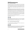
2.1 Starting Maestro...................................................................................................3
2.2 General Interface Design .....................................................................................4
2.2.1 Maestro Windows.....................................................................................5
2.2.2 Mouse Functions ......................................................................................5
2.3 The Maestro Main Window .................................................................................6
2.3.1 The Toolbar .............................................................................................7
2.3.2 Shortcut Keys .........................................................................................10
2.4 Maestro Workflow .............................................................................................11
2.5 Maestro Projects ................................................................................................11
2.6 Job Launching and Incorporation ......................................................................12
2.7 Undoing Workspace Operations ........................................................................14
2.7.1 Undoing Operations on the Structures ...................................................14
2.7.2 Undoing Operations on the View ...........................................................15
2.8 Ending a Maestro Session..................................................................................15
Chapter 3: Importing and Exporting Structures and Data............................17
3.1 Importing Structures ..........................................................................................17
3.1.1 Selecting Files ........................................................................................18
3.1.2 Selecting Import Settings .......................................................................20
3.1.3 Error Reporting for PDB Files ...............................................................21
3.1.4 Entry Naming Conventions for Imported Structures .............................22
3.1.5 Reading Jaguar Input Files.....................................................................22
3.2 Exporting Structures ..........................................................................................23
3.2.1 Selecting Export Settings .......................................................................24
3.2.2 Exporting Multiple Files ........................................................................25
3.3 Exporting Data to a Spreadsheet........................................................................26
3.4 Importing Data from a Spreadsheet ...................................................................28
Chapter 4: Building Structures.........................................................................31
4.1 The Build Panel..................................................................................................31
4.2 Building a Structure From Fragments ...............................................................32
4.2.1 Building Structures Using Place Mode ..................................................34
4.2.2 Building Structures Using Grow Mode..................................................36
Maestro 6.5 User Manual
iii
Contents
4.3 Building a Structure From Atoms......................................................................36
4.4 Changing Elements ............................................................................................38
4.5 Changing the Bond Order and Formal Charge ..................................................39
4.6 Fusing or Connecting Structures........................................................................40
4.7 Adjusting the Geometry.....................................................................................42
4.8 Applying a Hydrogen Treatment .......................................................................43
4.9 Changing Atom Properties.................................................................................45
4.10 Changing Residue Properties...........................................................................49
4.11 Defining Dummy Atoms..................................................................................50
4.12 Deleting Atoms ................................................................................................51
Chapter 5: Selecting Atoms ...............................................................................53
5.1 The Pick Menu...................................................................................................53
5.2 The Atom Selection Dialog Box........................................................................54
5.2.1 Selecting Atoms by Property .................................................................55
5.2.2 Combining and Modifying Atom Selections .........................................56
5.2.3 Selecting Atoms by Proximity ...............................................................56
5.2.4 Editing and Storing Expressions ............................................................57
5.2.5 Examples of Atom Selection..................................................................57
Chapter 6: Displaying Structures......................................................................59
6.1 Changing Atom Color........................................................................................59
6.1.1 Applying a Single Color.........................................................................59
6.1.2 Using Predefined Schemes to Color Atoms ...........................................61
6.2 Changing Molecular Representations ................................................................61
6.2.1 Changing the Representation of Atoms .................................................61
6.2.2 Changing the Representation of Bonds..................................................62
6.2.3 Changing Representation Attributes ......................................................64
6.2.4 Rendering Proteins as Ribbons ..............................................................65
6.3 Labeling Atoms..................................................................................................67
6.4 Displaying and Undisplaying Atoms .................................................................69
Chapter 7: Manipulating Structures.................................................................71
7.1 Global Transformations .....................................................................................71
7.2 Local Transformations .......................................................................................72
7.2.1 Selecting Atoms for Transformation......................................................73
7.2.2 Selecting a Rotation Center....................................................................74
7.3 Tiling Multiple Entries.......................................................................................74
iv
Maestro 6.5 User Manual
Contents
Chapter 8: Projects.............................................................................................75
8.1 Project Operations..............................................................................................75
8.1.1 Creating and Opening Projects...............................................................75
8.1.2 Saving and Closing Projects...................................................................76
8.1.3 Deleting Projects ....................................................................................76
8.1.4 The Project Selector Panels....................................................................77
8.1.5 Annotating a Project...............................................................................78
8.2 Adding Entries to a Project ................................................................................78
8.2.1 Importing Structures From a File ...........................................................78
8.2.2 Creating Entries From Workspace Structures ........................................79
8.2.3 Incorporating Entries From Job Output .................................................79
8.2.4 Merging Entries From Another Project..................................................79
8.3 The Project Table Panel .....................................................................................80
8.3.1 The Project Table Toolbar ......................................................................81
8.3.2 The Project Table Menus........................................................................82
8.3.3 Mouse Functions in the Project Table ....................................................83
8.3.4 Project Table Shortcut Keys ...................................................................84
8.3.5 Configuring the Project Table ................................................................84
8.3.6 Finding Text in the Project Table ...........................................................85
8.4 Selecting Project Entries ....................................................................................85
8.4.1 The Select Menu ....................................................................................86
8.4.2 The Entry Selection Dialog Box ............................................................86
8.4.3 Selecting Entries Using the Plot Panel...................................................88
8.4.4 Selection Examples ................................................................................88
8.5 Operating on Selected Entries............................................................................89
8.5.1 Including, Excluding and Fixing Entries ...............................................89
8.5.2 Limiting the Number of Entries Displayed ............................................89
8.5.3 Renaming Entries ...................................................................................89
8.5.4 Duplicating Entries.................................................................................90
8.5.5 Merging Multiple Entries .......................................................................90
8.5.6 Splitting Entries by Molecule.................................................................90
8.5.7 Deleting Entries......................................................................................91
8.5.8 Moving Entries.......................................................................................91
8.5.9 Sorting the Entries of a Project ..............................................................91
8.6 The ePlayer ........................................................................................................92
8.6.1 ePlayer Modes ........................................................................................93
8.6.2 ePlayer Options ......................................................................................93
Maestro 6.5 User Manual
v
Contents
8.7 Entry Properties .................................................................................................95
8.7.1 Creating New Properties ........................................................................95
8.7.2 Changing Property Values......................................................................97
8.7.3 Renaming and Deleting Properties.........................................................99
8.7.4 Displaying Selected Properties ............................................................100
8.7.5 Moving and Resizing Property Columns .............................................100
8.7.6 Exporting and Importing Data .............................................................101
8.8 Undoing Project Operations.............................................................................101
Chapter 9: Tools................................................................................................103
9.1 Displaying Markers..........................................................................................103
9.2 Making Measurements in the Workspace ........................................................103
9.2.1 Measuring Distances, Angles, and Dihedrals.......................................103
9.2.2 Displaying Hydrogen Bonds and Contacts ..........................................105
9.2.3 Storing the Results of Measurements...................................................106
9.2.4 Defining Dummy Atoms for Measurements ........................................107
9.3 Superimposing Structures ................................................................................107
9.4 Sets...................................................................................................................109
9.4.1 Creating and Deleting Sets...................................................................109
9.4.2 Selecting Atoms for a Set.....................................................................109
9.4.3 Creating Sets With Boolean Operators ................................................110
9.4.4 Reading and Writing Sets.....................................................................111
9.5 Assigning and Aligning Protein Structures .....................................................111
Chapter 10: Plotting .........................................................................................113
10.1 Creating Plots ................................................................................................113
10.2 Viewing and Manipulating Plots....................................................................114
10.2.1 Selecting Plots ....................................................................................115
10.2.2 Panning and Zooming ........................................................................116
10.2.3 Labeling and Unlabeling Data Points ................................................116
10.2.4 Selecting and Deselecting Project Entries..........................................117
10.2.5 Including and Excluding Project Entries............................................117
10.3 Editing Plots and Plot Settings.......................................................................117
10.3.1 Modifying Plot Attributes ..................................................................118
10.3.2 Operating on Plot Series ....................................................................119
10.3.3 Changing X and Y Axis Display........................................................120
10.4 Updating Plots to Reflect Project Table Changes ..........................................121
10.5 Saving Plot Images ........................................................................................122
vi
Maestro 6.5 User Manual
Contents
Chapter 11: Surfaces........................................................................................123
11.1 Generating Surfaces .......................................................................................123
11.1.1 Surface Generation Controls ..............................................................123
11.1.2 Molecular Structure Surfaces .............................................................125
11.1.3 Extended Radius Surfaces..................................................................125
11.1.4 van der Waals Surfaces.......................................................................126
11.2 Sitemaps.........................................................................................................127
11.2.1 Background ........................................................................................127
11.2.2 Mapping Algorithm............................................................................128
11.2.3 Specifying a Structure to Be Mapped ................................................129
11.2.4 Defining the Mapping Box.................................................................130
11.2.5 Running the Sitemap Job ...................................................................130
11.2.6 Viewing the Sitemap Surface .............................................................131
11.3 Importing Surface or Volume Files................................................................131
11.4 The Surface Table Panel ................................................................................132
11.4.1 Changing the Appearance of the Surface ..........................................132
11.4.2 Selecting a Color Scheme ..................................................................134
11.4.3 Creating, Changing and Deleting Surfaces ........................................135
11.4.4 Importing Surfaces ............................................................................136
Chapter 12: Customizing Maestro..................................................................137
12.1 Changing and Saving Panel Layout ...............................................................137
12.2 Setting Preferences ........................................................................................137
12.2.1 Deleting Markers Upon Connectivity Change ...................................138
12.2.2 Changing Font Size for Interface Component Text............................138
12.2.3 Setting Project Synchronization and Storage Preferences .................139
12.2.4 Specifying a Default Working Directory............................................141
12.2.5 Customizing Atom Label Appearance ..............................................141
12.2.6 Setting Mouse Preferences .................................................................142
12.2.7 Setting File Suffix Preferences ...........................................................143
12.2.8 Setting Builder Preferences................................................................144
12.3 Customizing the Workspace ..........................................................................145
12.3.1 Showing or Hiding Controls and Displays.........................................146
12.3.2 Setting the Background Color ............................................................146
12.3.3 Specifying a Stereo Viewing Method.................................................146
12.3.4 Enabling Perspective ..........................................................................147
12.3.5 Enabling Fog ......................................................................................147
12.3.6 Depth Cues .........................................................................................149
12.4 Creating Command Aliases ...........................................................................150
Maestro 6.5 User Manual
vii
Contents
12.5 Customization Using Command Scripts........................................................151
12.5.1 Command History ..............................................................................151
12.5.2 Building a Command Script...............................................................152
12.5.3 Saving a Command Script..................................................................153
12.5.4 Opening Existing Command Scripts ..................................................153
12.5.5 Running and Stopping Scripts............................................................153
12.5.6 Customizations You Can Perform With a Script................................153
12.6 Creating Macros.............................................................................................155
Chapter 13: Printing and Saving Workspace Images ...................................157
13.1 Printing an Image (File or Printer).................................................................157
13.2 Creating TIFF and JPEG Image Files............................................................159
Chapter 14: Job Control ..................................................................................161
14.1 Configuring Job Control ................................................................................161
14.1.1 The Scratch Directory ........................................................................161
14.1.2 Preparing for Remote Job Submission ...............................................162
14.1.3 The schrodinger.hosts File.....................................................163
14.1.4 Software Version Selection ................................................................166
14.2 Monitoring Jobs .............................................................................................167
14.3 Managing Jobs ...............................................................................................169
14.3.1 Controlling Jobs From the Monitor Panel..........................................169
14.3.2 Controlling Jobs From the Command Line........................................169
14.4 The Job Database ...........................................................................................172
14.4.1 The Job Record ..................................................................................172
14.4.2 Purging the Job Database ...................................................................173
14.5 Running Jobs from the Command Line .........................................................174
14.6 Incorporation of Job Output...........................................................................176
Chapter 15: Help...............................................................................................179
15.1 Maestro Online Help......................................................................................179
15.1.1 Locating a Topic by Searching...........................................................179
15.1.2 Locating a Topic by Category ............................................................180
15.1.3 Searching Within a Topic ...................................................................180
15.2 Context-Sensitive Help ..................................................................................181
15.3 Manuals and Release Notes ...........................................................................182
15.4 The Schrödinger Web Site .............................................................................182
15.5 Technical Support ..........................................................................................182
viii
Maestro 6.5 User Manual
Contents
Appendix A: The Maestro File Format ..........................................................185
A.1 Basic File Description ....................................................................................185
A.2 Data Blocks ....................................................................................................185
A.3 Compressed Format .......................................................................................187
A.4 Data Item Names ............................................................................................187
A.5 Example Maestro File ....................................................................................187
Appendix B: Atom Types .................................................................................191
Appendix C: Entry Suffixes .............................................................................197
Appendix D: Utilities ........................................................................................199
D.1 Structure Conversion ......................................................................................199
D.1.1 Conversions to and From MacroModel Format ..................................199
D.1.2 Conversions to and From Mol2 Format ..............................................200
D.1.3 Conversions to and From PDB Format: pdbconvert .....................200
D.1.4 Conversions to and From SD Format: sdconvert ..........................202
D.2 Structure Extraction .......................................................................................203
D.3 Display of Properties ......................................................................................205
D.4 Structure Preparation .....................................................................................206
Glossary .............................................................................................................209
Index ..................................................................................................................211
Maestro 6.5 User Manual
ix
Contents
x
Maestro 6.5 User Manual
Chapter 1:
Document Overview
This manual contains an introduction to the Maestro graphical user interface (GUI) and a
description of how to use Maestro’s settings, panels, and features to build, import, and
manipulate molecular structures. No prior knowledge of Maestro is assumed. If you
cannot find the information you are looking for in this document, see the Maestro online
help. For help with preparing and starting computations, see the user manual for the
related product. For a list of features that are new in this version of Maestro, see the
Maestro Release Notes.
In addition to the normal use of italics for names of documents, the font conventions that
are used in this manual are summarized in Table 1.1.
In descriptions of command syntax, the usual UNIX conventions are used: braces { }
enclose a choice of required items, square brackets [ ] enclose optional items, and the
pipe symbol | separates items in a list from which one item must be chosen. Angle
brackets < > are used to denote user replacement text in expressions whose components
are not separated by spaces. Lines of command syntax that wrap should be interpreted as a
single command.
In this document, to type a command means to type the required text in the specified location, and to enter a command means to type the required text and then press the ENTER
key.
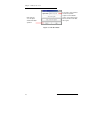
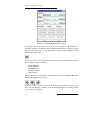
Table 1.1. Font conventions.
Font
Example
Use
Sans serif
Project Table
Names of GUI features such as panels,
menus, menu items, buttons, labels
Monospace
$SCHRODINGER/maestro
File names, directory names, commands, and
environment variables
Italics
filename
Text that the user must replace with a value
Sans serif
uppercase
ALT+H
Keyboard keys
The use of this version of Maestro should be cited in publications as:
Maestro 6.5, Schrödinger, LLC, Portland, OR, 1999–2004.
Maestro 6.5 User Manual
1
Chapter 1: Document Overview
2
Maestro 6.5 User Manual
Chapter 2:
Maestro Overview
Maestro™ is the graphical user interface (GUI) for all of Schrödinger’s computational
programs: FirstDiscovery™ (Glide™, Impact™, Liaison™, QSite™), Jaguar™, LigPrep™,
MacroModel®, Prime™, and QikProp™. It contains tools for building, displaying, and
manipulating chemical structures; for organizing, loading and storing these structures and
associated data; and for setting up, submitting, monitoring, and visualizing the results of
calculations on these structures. Maestro’s job control facility manages jobs submitted
from Maestro and from the command line to both local and remote hosts.
The Maestro interface uses the OpenGL graphics tools, and can take advantage of hardware graphics capabilities, including stereo viewing capabilities. Maestro runs on SGI and
Linux platforms. For information on Maestro requirements, software and hardware, see
the Schrödinger Product Installation Guide. For information on configuring stereo
viewing, see Section 12.3 on page 145.
This chapter provides an overview of Maestro—the general interface design, starting and
ending a Maestro session, the main window and its features, Maestro projects and workflow, and running jobs from Maestro.
2.1
Starting Maestro
Before you start Maestro, you must set the SCHRODINGER environment variable to point
to the installation directory. You can set this variable by entering the following command
at a shell prompt:
csh/tcsh:
bash/ksh:
setenv SCHRODINGER installation-directory
export SCHRODINGER=installation-directory
You might also need to set the DISPLAY environment variable if it is not set automatically
when you log in. To determine if you need to set this variable, enter the command
echo $DISPLAY
If the response is a blank line, set the variable by entering the following command.
csh/tcsh:
bash/ksh:
setenv DISPLAY display-machine-name:0.0
export DISPLAY=display-machine-name:0.0
After you set the SCHRODINGER and DISPLAY environment variables, you can start
Maestro using the command
$SCHRODINGER/maestro [options] [filename]
Maestro 6.5 User Manual
3
Chapter 2: Maestro Overview
The options for the maestro command are listed in Table 2.1. The optional filename
specifies a file in Maestro or MacroModel format.
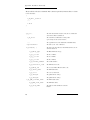
Table 2.1. Options for the maestro command.
Option
Description
-b PDB-file
Read a PDB file. Cannot be used with -m.
-c command-script
Run the specified Maestro command script when Maestro starts.
-h
Print a usage message, but do not start Maestro.
-m filename
Load structures from a Maestro (.mae) or MacroModel (.dat) structure file. Cannot be used with -b. The -m can be omitted if this option is
at the end of the option list.
-p project
Load the specified Maestro project.
-s number
Specify the first structure to load when a Maestro file is specified for
loading.
-t number
Specify the total number of structures to load when a Maestro file is
specified for loading.
-v
Display the Maestro version number, but do not start Maestro.
-I
Display extra information about X visual settings when Maestro starts.
-SGL
Use the Schrödinger-supplied OpenGL library. The default is to use the
system OpenGL library.
The directory from which Maestro was started becomes Maestro’s current working directory, and all data files are written to and read from this directory unless otherwise specified. You can change directories by entering the following command, either at the shell
prompt before you start Maestro, or in the command input area of the Maestro main
window:
cd directory_name
where directory_name can be either a full path or a relative path.
2.2
General Interface Design
The Maestro interface design makes use of most of the common features of interface
design, but it has some characteristics that are unique. The general operation of the
Maestro interface is described in this section. Other interface features that are specific to
Maestro are described in the relevant sections or chapters.
4
Maestro 6.5 User Manual
Chapter 2: Maestro Overview
2.2.1
Maestro Windows
Most of the windows that are opened from Maestro are amodal, and are called panels.
More than one panel can be open at any given time, and a panel need not be closed for an
action to be carried out. Panels are closed by clicking the Hide button. This button replaces
the Close button or the Close menu item found in other interfaces.
Maestro also has dialog boxes, which are modal: they must be closed before you can carry
out an action in any other panel. Dialog boxes must be closed for the action to be carried
out. Some dialog boxes allow you to carry out limited operations in other panels such as
the Workspace, and some dialog boxes allow you to open the help viewer so that you can
obtain information about the dialog box.
2.2.2
Mouse Functions
The mouse functions that are common to graphical user interfaces are supported in
Maestro:
• The left button is used for selecting: choosing menu items, clicking buttons and
selecting objects. This button is also used for resizing and moving panels. In the
description of mouse actions, “click” always means left-click.
• The right button is used for opening a context-sensitive menu, where these menus are
available.
• Shift-click is used to select a contiguous range of items in a list, and control-click is
used to select and deselect a single item in a list without affecting the selection of
other items.
• Dragging operations are supported. For example, in the Project Table, dragging
selected entries allows you to reposition the entries; dragging a column heading
moves the column; dragging with the middle mouse button on the boundary of a row
or column resizes the row or column.
If you have the handedness on your mouse set to “left,” the mouse functions are the mirror
image of those described: the right mouse button is used for picking, and the left button is
used for context-sensitive menus.
If you have a two-button mouse, ensure that it is configured for three-button mouse simulation. Then the middle mouse button is simulated by pressing or holding down both
buttons.
The Workspace has special uses for the middle and right mouse buttons. These are used on
their own and in combination with the SHIFT and CTRL keys to perform common operations such as rotation, translation, centering, and zooming. See Chapter 7 for more information.
Maestro 6.5 User Manual
5
Chapter 2: Maestro Overview
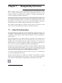
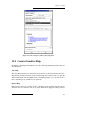
2.3
The Maestro Main Window
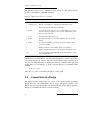
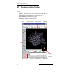
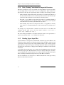
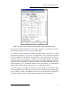
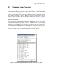
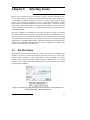
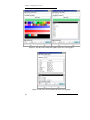
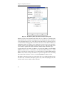
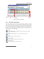
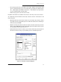
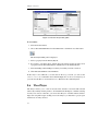
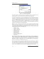
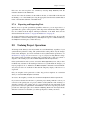
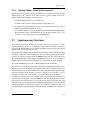
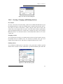
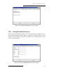
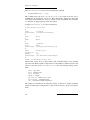
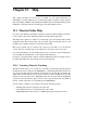
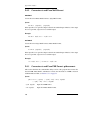
The Maestro main window is shown in Figure 2.1. The main window components are as
follows:
• Title bar—displays the project name and the current working directory
• Auto-Help—automatically displays context-sensitive help
• Main menu bar—provides access to panels
• Workspace—displays molecular structures
Title bar
Auto-Help text area
Main menu bar
Workspace
Toolbar
Viewing
volume
indicator
Sequence viewer
Status bar
Command input area
Clipping plane
Figure 2.1. The Maestro main window.
6
Maestro 6.5 User Manual
Chapter 2: Maestro Overview
• Clipping planes window—displays a small, top view of the Workspace and shows
the clipping planes and viewing volume indicators
• Toolbar—contains buttons for many common tasks, and also provides tools for displaying and manipulating structures and organizing the Workspace
• Status bar—displays the number of atoms, entries, residues, chains, and molecules
in the Workspace
• Sequence viewer—shows the sequences for proteins displayed in the Workspace
• Command input area—provides a place to enter Maestro commands
You can show or hide any of the last five of these from the Display menu. By default, all of
these are displayed except the clipping planes window. You can show or hide the toolbar,
the status bar, and the sequence viewer by clicking their collapse buttons:
When a distinction between components in the main window and those in other panels is
needed, the term main is applied to the main window components (e.g., main toolbar).
2.3.1
The Toolbar
The main toolbar contains buttons for performing common tasks. There are three kinds of
buttons on the toolbar:
• Those that perform simple tasks, like clearing the Workspace
• Those that show and hide panels or open dialog boxes
• Those that display a menu when you click and hold
The third type of button is called a menu button and has a triangle in the lower right corner.
The menu is called a button menu. There are two kinds of items on button menus, and both
kinds can be on the same menu:
• Actions, which perform an action immediately
• States, which you set before an action is performed
When you select a state, it is stored and marked with a red diamond on the menu. Most
states on button menus are pick states (see Section 5.2 on page 54), which means you must
pick an atom in the Workspace before the action is performed. If you click a menu button
that has pick states, the button is indented to indicate that picking with the selected pick
state is in effect. If you double-click a menu button that has pick states, the action is
applied to all atoms. Some other menu buttons support double-clicking to apply an action:
this support is explicitly mentioned in the button description.
Maestro 6.5 User Manual
7
Chapter 2: Maestro Overview
You can show or hide the toolbar using the collapse button at the top or by selecting
Toolbar from the Display menu. You can hide it or move it to the right or left side of the
Workspace by right-clicking in the toolbar and selecting the appropriate option. The
buttons are described below.
Open a project
Open the Open Project dialog box.
Import structures
Show the Import panel.
Show/Hide project table
Show the Project Table panel or hide it
if it is displayed.
Save as
Open the Save Project As dialog box,
to save the project with a new name.
Create entry from workspace
Create an entry in the current project
using the contents of the Workspace.
Delete
Choose an object to delete. Menu button
with a pick menu, a section to delete
hydrogens and waters and to open the
Atom Selection dialog box, and a section to delete other objects associated
with the structures in the Workspace.
Show/Hide Build panel
Show the Build panel or hide it if it is
displayed.
Add hydrogens
Pick atoms for hydrogen treatment.
Menu button with a pick menu and an
item to open the Atom Selection dialog
box.
Local transformation
Pick the object to transform. Menu button with a pick menu and an item to
open the Advanced Transformations
panel.
Undo/Redo
Undo or redo the last action. Performs
the same function as the Undo item on
the Edit menu, and changes to an arrow
pointing in the opposite direction when
an Undo has been performed, indicating
that its next action is Redo.
Fit to screen
Scale what is displayed to fit into the
Workspace, and reset the center of rotation.
Clear workspace
Clear all atoms from the Workspace
Set fog display state
Menu button. Automatic means on when
there are more than 40 atoms in the
Workspace, off when there are fewer.
Enhance depth cues
Optimize fogging and other depth cues
based on what is in the Workspace.
Rotate around X axis by 90 degrees
Rotate around Y axis by 90 degrees
8
Maestro 6.5 User Manual
Chapter 2: Maestro Overview
Tile entries
Arrange entries in a rectangular grid in
the Workspace.
Reset workspace
Reset the rotation, translation, and zoom
of the Workspace to the default state.
Save view
Save the current view of the Workspace:
orientation, location, and zoom.
Restore view
Restore the last saved view of the Workspace: orientation, location, and zoom.
Display only picked atoms
Pick atoms to display. Menu button with
a pick menu.
Display only
Display only the selected atoms. Menu
button with a list of predefined atom categories and an item to open the Atom
Selection dialog box.
Also display
Add the selected atoms to the display.
Menu button with a list of predefined
atom categories and an item to open the
Atom Selection dialog box.
Undisplay
Undisplay the selected atoms. Menu
button with a list of predefined atom categories and an item to open the Atom
Selection dialog box.
Display residues within N angstroms
of currently displayed atoms
Menu button with a list of values and an
item to open a dialog box to set a value.
Show, hide, or color ribbons
Menu button with items to control the
display of ribbons and atoms for proteins and to color ribbons by various
schemes.
Draw bonds in wire
Pick atoms for representation. Menu
button with a pick menu and an item to
open the Atom Selection dialog box.
Draw atoms in CPK
Pick atoms for representation. Menu
button with a pick menu and an item to
open the Atom Selection dialog box.
Draw atoms in ball and stick
Pick atoms for representation. Menu
button with a pick menu and an item to
open the Atom Selection dialog box.
Draw bonds in tube
Pick atoms for representation. Menu
button with a pick menu and an item to
open the Atom Selection dialog box.
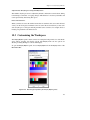
Color all atoms by scheme
Menu button with a list of schemes.
Color residue by constant color
Pick residues to apply the selected color.
Double-click to color all atoms. Menu
button with a list of colors.
Label atoms
Label all atoms with the selected label.
Menu button with a list of label types
and an item to delete labels.
Label picked atoms
Menu button with a pick menu and
items to open the Atom Selection dialog
box, to open the Atom Labels panel at
the Composition folder, and to delete
labels.
Maestro 6.5 User Manual
9
Chapter 2: Maestro Overview
Measure distances, angles or dihedrals
Pick atoms to define measurements.
Menu button with items to choose
between distance (default), angle, or
dihedral measurement, and to delete
measurements.
Display H-bonds
Pick molecules to display H-bonds.
Menu button with items to choose to
display H-bonds within the selected
molecule (intra) or between the selected
molecule and all other atoms in the
Workspace (inter), or to delete H-bonds.
2.3.2
Shortcut Keys
Some frequently used operations in the main window have been assigned shortcut key
combinations. The shortcuts, their functions, and their menu equivalents are listed in
Table 2.2. Shortcut keys in the Project Table panel and the Plot panel are listed in the chapters that describe those panels.
Table 2.2. Shortcut keys in the Maestro main window.
Keys
Action
Equivalent Menu Choice
ALT+B
Show build panel
Edit > Build
ALT+C
Create entry
Project > Create Entry From Workspace
ALT+E
Show script panel
Edit > Command Script Editor
ALT+H
Show help panel
Help > Help
ALT+I
Show import panel
Project > Import Structures
ALT+M
Show measurement panel
Analysis > Measurement
ALT+N
New project
Project > New Project
ALT+O
Open project
Project > Open Project
ALT+P
Print
Maestro > Print
ALT+Q
Quit
Maestro > Quit
ALT+S
Show sets panel
Analysis > Sets
ALT+T
Show project table panel
Project > Show Table
ALT+W
Close project
Project > Close Project
ALT+Z
Undo/Redo last command
Edit > Undo/Redo
10
Maestro 6.5 User Manual
Chapter 2: Maestro Overview
2.4
Maestro Workflow
For most operations that you perform in Maestro, you must first define or choose an
action, then choose the atoms to which the action will be applied. For example, to change
the color of all atoms in a displayed structure to the color green, you first select the color
from the Atom Coloring panel, and then pick the atoms to be colored. In many cases, you
can review the selection before applying the action.
Most operations are chosen by opening a panel or a folder. Selecting the atoms to apply
the operation to is called picking. To pick an atom or a group of atoms, you can click on
the relevant structural elements in a Workspace structure, such as atoms or residues. Each
panel, folder or dialog box that requires a choice of atoms has a set of picking tools, which
vary according to the flexibility needed in the choice of atoms. These tools are described
in detail in Chapter 5.
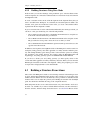
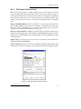
2.5
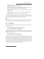
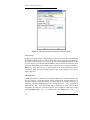
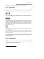
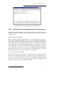
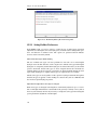
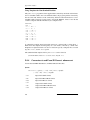
Maestro Projects
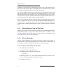
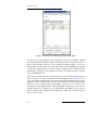
When you use Maestro, you are always working within a project. A project is a collection
of chemical structures and their associated data. These structures and their data are organized into entries, each of which can consist of multiple molecules and their properties.
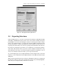
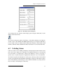
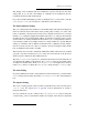
The project is represented in the Project Table, which displays an ordered list of entries
and any associated data. You can open the Project Table panel by choosing Show Table
from the Project menu, or by clicking the Show/Hide project table button on the toolbar.
If you do not specify a project when you start Maestro, Maestro creates a scratch project.
You can work in a scratch project, but you must save it in order to use it in future sessions.
Entries are represented by rows in the Project Table. Each row contains the row number,
the title, the entry’s Workspace inclusion state (the In column), a button to open the
Surfaces panel if there are surfaces associated with the entry, the entry name, and any
properties associated with the entry. If there are no surfaces associated with any entry, the
Surf column of the Project Table is empty.
You control which entries are displayed in the Workspace from the Project Table. You can
use entries as input for most of the computational programs: Glide, Jaguar, LigPrep,
MacroModel, Prime, QikProp, and QSite. You can select entries as input for the ePlayer,
which displays the selected structures in sequence. You can duplicate, combine, rename,
split, and sort entries; create properties for entries, import structures as entries, and export
entries in various formats. Although the Project Table does not have spreadsheet capabilities, you can export properties to and import properties from a spreadsheet.
Maestro 6.5 User Manual
11
Chapter 2: Maestro Overview
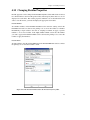
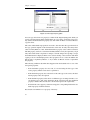
Figure 2.2. The Project Table panel.
When you build molecules in the Workspace, they constitute the scratch entry until you
choose to save the structures as project entries. The scratch entry is not saved with the
project unless you explicitly add it to the project. However, you can use a scratch entry as
input for some jobs, and the results can be incorporated.
More information on projects is given in Chapter 8.
2.6
Job Launching and Incorporation
Maestro’s job launching and incorporation capabilities are designed to make it easy to
manage multiple structures and their passage though multiple computational programs,
without having to deal with the details of the file system.
For all computational programs, the Monitor panel is automatically displayed when the job
is launched, and job progress is posted to the monitor window. You may cease or resume
monitoring at any time, and you can monitor any currently running job. If a job finishes
while it is being monitored, its output is incorporated into the current project immediately.
If you choose to monitor an already completed (but not yet incorporated) job, the output of
that job is incorporated.
For more information on job control and incorporation, see Chapter 14.
LigPrep, MacroModel, and QikProp
These computational programs, which have been fully integrated with the Project Facility,
can use Maestro structure files, single or multiple project entries and structures displayed
in the Workspace as input, and can incorporate job results into the project. You can specify
whether the output structures will be appended to the project, replace the input entries, or
12
Maestro 6.5 User Manual
Chapter 2: Maestro Overview
be ignored when the job finishes. As the job progresses, any interim structures are shown
in the Workspace.
In addition, LigPrep jobs can read structures from external files. This choice of structural
input has no connection with a Maestro project, so the output is required to be written to
an external file.
Jaguar
Jaguar maintains its own input and output files and directory structure. However, it can use
Maestro structure files, project entries and structures displayed in the Workspace for
geometry input, and inherits default directory and file settings from Maestro. Jaguar can
also use multiple entries selected from the Project Table as input for jobs. As for MacroModel, any changes to the structure are displayed in the Workspace as the job proceeds.
Jaguar jobs launched from Maestro are automatically monitored and the results incorporated into the project as new entries. Numerical data such as the total energy are included
as entry properties. Data for display of surfaces and vibrational data are automatically
incorporated when the job input comes from the Project Table.
FirstDiscovery
The programs comprising the FirstDiscovery suite have differing degrees of integration
with the Project Facility. Glide can use selected entries from the project table as input for
docking, but does not incorporate the results. The pose files that are generated are better
viewed in the Glide Pose Viewer than in the Project Table. Liaison is not integrated with
the project facility at all: Liaison takes input from specified disk files or the Workspace,
and the results are not incorporated. QSite and Impact are integrated into the Project
Facility. Either the Workspace or a single selected entry can be used as the source of job
input, and the incorporation mode can be selected. Protein preparation uses the Workspace
structure as input and the resulting structures are incorporated.
For the programs that do not incorporate results, the output files are placed in the file i/o
directory that you specify using the Preferences panel.
Prime
Prime’s Protein Structure Prediction works on a different model from other products. The
input is a sequence rather than a structure, though the sequence can be taken from a structure in the Workspace. Output from each step is incorporated into the next step, but not via
the Project Table. At the final step, the structures can be copied into the Project Table. The
standalone Refinement facility is similar to MacroModel and QikProp: it takes the structure in the Workspace as input and incorporates the results into the Project Table according
to the selected option.
Maestro 6.5 User Manual
13
Chapter 2: Maestro Overview
2.7
Undoing Workspace Operations
There are two classes of operations in the Workspace: operations that act on the structure,
and operations that act on the view of the molecule. The former include local transformations, other coordinate changes, and adding or removing atoms from the display. The latter
include global transformations: translation, rotation, and magnification (zoom). These
operations do not change the coordinates recorded in the project entry, but store a local
copy that is translated, rotated, or magnified.
2.7.1
Undoing Operations on the Structures
Single operations in the Workspace can be undone by choosing Undo action from the Edit
menu. This item is dynamic: its name includes a description of the undoable actions, and
changes to Redo after it has been used. Selecting Redo action reimplements the action that
was undone. This menu item is mapped to the Undo/Redo button on the toolbar.
To undo the last operation, do one of the following:
• Click the Undo/Redo button on the toolbar.
• Choose Undo action from the Edit menu.
• Type ALT+Z.
If you want to be able to undo more than one operation, you can define an Undo Block.
The Undo Block groups a sequence of commands so that the effect of the entire sequence
can be reversed. This is particularly useful for risky or complicated procedures.
To define an Undo block:
1. Choose Begin Undo Block from the Edit menu.
2. Perform the sequence of operations that you want to be able to undo.
3. Choose End Undo Block from the Edit menu.
To undo the operations in an Undo block:
• Choose Undo action from the Edit menu, type ALT+Z, or click the Undo/Redo button
in the toolbar.
As for a single action, the Undo option for a block changes to Redo once you have used it.
14
Maestro 6.5 User Manual
Chapter 2: Maestro Overview
Maestro itself can perform certain actions (such as job monitoring) from within undo
blocks. These actions might prevent the entire sequence of operations from being undone.
2.7.2
Undoing Operations on the View
Global molecular transformations, such as rotations and translations, cannot be undone
with the Undo option on the Edit menu or in Undo Blocks. To undo such a transformation,
you must save the orientation of the structure before you do the global transformation. You
can also revert to the default orientation and zoom. The default orientation is defined by
the coordinates of the structure. The default zoom value is the value you get by clicking
the Fit to screen button on the toolbar.
To save an orientation:
• Click the Save view button in the toolbar.
To restore the saved orientation:
• Click the Restore view button in the toolbar.
To revert to the default orientation and zoom:
• Click the Reset workspace button in the toolbar.
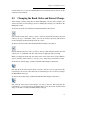
2.8
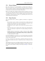
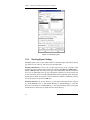
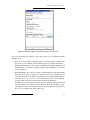
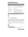
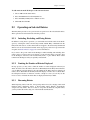
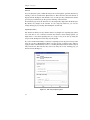
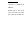
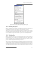
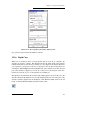
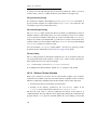
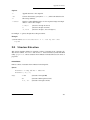
Ending a Maestro Session
To end a Maestro session, choose Quit from the Maestro menu. If you would like to save a
log file with a record of all operations performed in the current session, click Quit, save log
file on the Quit panel. This information can be useful to Schrödinger support staff when
responding to any problem you report. If you do not want to save a log file, click the
default Quit, do not save log file button. If you are working in a scratch project and you
have not saved the project, you will be prompted to do so.
Maestro 6.5 User Manual
15
Chapter 2: Maestro Overview
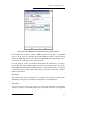
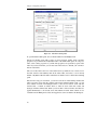
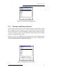
If you want to save a file that
records the operation
sequence for this Maestro
session, enter a name for the
file here, and then click Quit,
save log file
Click Cancel to
close the panel
and abort the Quit
operation
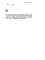
Figure 2.3. The Quit Panel.
16
Maestro 6.5 User Manual
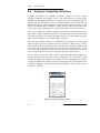
Chapter 3:
Importing and Exporting
Structures and Data
The primary place for reading and writing data from Maestro is a project. When you open
a project, the structures and data from that project are read into Maestro. As you modify
structures and data they are automatically saved in the project (unless you have selected an
option not to do so). Projects are described in detail in Chapter 8. In addition to reading
and writing to projects, Maestro can also read and write structural information in a variety
of formats, including its own native Maestro format, MacroModel, PDB, Sybyl Mol2, and
MDL SD format. Through the Jaguar panel, structural information can be obtained from
the input and output files of a wide variety of quantum chemical programs.
Obtaining structures from a file in Maestro is called importing rather than reading because
the structures are imported into the current project. Any structures that do not exist as
entries in the current project are external to the project, and therefore must be imported.
Similarly, the term exporting is used instead of writing because a file is created for use
outside the current project.
Data that is associated with structures can also be imported and exported independently to
spreadsheet files. This capability enables properties that are created by Schrödinger software to be read by a spreadsheet program, manipulated, and re-imported into the project.
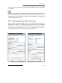
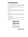
3.1
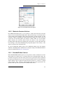
Importing Structures
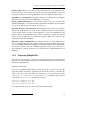
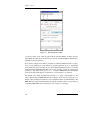
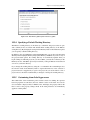
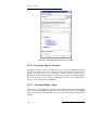
Structures are imported using the Import panel. You can import data from files in Maestro,
MacroModel, PDB, Sybyl Mol2, MDL SD, and a range of other formats. If the files
contain multiple structures, such as the output of a conformational search, you can select
the structures to import. When importing structures, Maestro places each structure into a
separate, new entry in the current project. For the Maestro file type, molecular representation information can be imported along with a structure. You can undo the import operation, but the changes made to the Project Table remain.
To open the Import panel, do one of the following:
• Choose Import Structures from the Project menu on the main menu bar.
• Choose Structures from the Import submenu of the Table menu in the Project Table
panel.
• Click the Import structures button on the main toolbar.
Maestro 6.5 User Manual
17
Chapter 3: Importing and Exporting Structures and Data
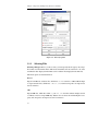
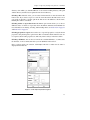
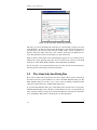
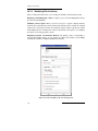
Figure 3.1. The Import panel.
3.1.1
Selecting Files
Selecting a file type: Before you choose files, you must specify the file type by choosing a
file format from the Format menu. This choice determines the file extensions to be used,
and thus the filter displayed in the Filter text box and the files displayed in the Files list.
The menu options are described below:
Maestro
Import from Maestro structure files, which have a .mae extension, or MacroModel input
or output structure files, which have .dat or .out extensions. Properties are imported as
well as structures.
PDB
Import PDB files, which have either a .pdb or a .ent extension. Where multiple atomic
coordinates exist for a single PDB entry, Maestro chooses the atoms with the highest occupancy ratio. Properties are imported as well as structures.
18
Maestro 6.5 User Manual
Chapter 3: Importing and Exporting Structures and Data
Mol2
Import Sybyl Mol2 files, which have a .mol2 extension.
SD
Import MDL SD files, which have either a .sdf extension for multiple structure files or a
.mol extension for files with a single structure. Properties are imported as well as structures.
Babel section
Import structures from a range of other programs. The format conversion is performed by
the program Babel. The list of formats provided here is a subset of the formats that Babel
can convert. If you want to import structures in other formats using Babel, you can use
Jaguar to read the files. See Section 3.1.5 on page 22 for more information. You can also
use Babel from the command line to convert structures to a format that Maestro can import
directly. To do so, you must first set the environment variable BABEL_DIR:
csh/tcsh: setenv BABEL_DIR $SCHRODINGER/mmshare-vver/data/babel
bash/ksh: export BABEL_DIR=$SCHRODINGER/mmshare-vver/data/babel
To obtain usage information, enter the babel command without arguments:
$SCHRODINGER/mmshare-vver/bin/platform/babel
Here, ver is the 5-digit mmshare version number, and platform indicates the platform on
which you are running, e.g. linux-x86.
Any
Import a file of any type. The file type is determined from the extension of the selected file
or the file name you enter in the Selection text box. If the extension is not unique, Maestro
does not import the file. The formats for which Maestro recognizes the extension are
Maestro, Mol and Mol2, PDB, SD, XYZ, Mopac Cartesian and Internal, and Spartan. This
option is useful if you want to locate any of these kinds of structure files.
Selecting a directory: To specify the directory from which to import, you can enter it in
the Path text box, navigate to it using the Directories list, or click Launch Directory or
Current Directory to select the directory from which you launched Maestro or the current
working directory. The path and the directory and file lists are updated for the chosen
directory.
Selecting a file: To select a file, you can type its name (and path) in the Selection text box,
or select it from the Files list.
Maestro 6.5 User Manual
19
Chapter 3: Importing and Exporting Structures and Data
If you selected one of the four specific file types from the first section of the menu, or
some of the Babel file types, the file that you select must have the correct extension. If you
type the name of the file in the Selection text box, you must include the correct extension.
In the Files list, only files with the correct extension are displayed.
If the file does not appear in the list, check that you have chosen the correct file type in the
Format section, or select All in the Format section to view all files. You can also view files
with a different extension by altering or deleting the filter and pressing RETURN or
clicking Filter.
Selecting multiple files: You can import structures from more than one input file at a
time. To select multiple input files, use the SHIFT and CTRL keys in combination with
mouse clicks to select as many files as you wish in the Files list, or click All Files to select
all files in the Files list.
3.1.2
Selecting Import Settings
Once you have selected the files to import structures from, you must choose which structures to import and how to display them.
Selecting structures to import: Maestro can import multiple structures from multiple
files. If you do not want to import all structures from each file, deselect Import all structures. You can then enter the index of the first structure in the Start text box, and the total
number of structures to import in the Total text box. You can import to the end of the file
by selecting End instead of specifying the total number. These settings are applied to all
files: they cannot be set for each file in a multiple file selection. To import different
numbers of structures from a set of files, select each file in turn and set the number of
structures to import.
Selecting structures to display: When you import structures from a file, you can set
options to control which structures to display, and whether the structures already in the
workspace are cleared or not. If Replace workspace is selected (the default setting),
Maestro automatically clears existing structures from the Workspace. To import new
structures without removing the Workspace contents, deselect Replace workspace.
To specify which structures are to be included in the workspace, choose one of the options
from the Include in workspace option menu: No Imported Structures, First Imported Structure, or All Imported Structures. The default is First Imported Structure. If you choose No
Imported Structures and Replace workspace is selected, the Workspace is cleared.
Importing graphical information: If you import structures from a Maestro file, you can
also import graphical information for the structures, such as the molecular representation.
Maestro’s default behavior is to read in and use this information when importing structures from a file. If you do not want imported structures to be displayed using the saved
representation information, clear the Use graphical info option.
20
Maestro 6.5 User Manual
Chapter 3: Importing and Exporting Structures and Data
3.1.3
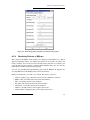
Error Reporting for PDB Files
When Maestro imports structures from PDB files, the color scheme it uses reflects the
success or failure of the placement of bonds. Maestro attempts to place bonds according to
a set of standard residue templates, the CONECT records of the PDB file, and geometry. If
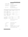
this placement of bonds fails, the regions of the structure in which problems were identified are colored according to the type of error. The color scheme is given in Table 3.1.
Table 3.1. Coloring scheme for structures imported from PDB files.
Color
Description
orange
Non-standard residues connected by geometry and/or CONECT records. Unless
duplicate CONECT records are specified, only single bonds are assigned, so
you will need to add multiple bonds.
red
Standard residue, but the input PDB file had missing atoms.
blue
A standard residue that has some atom names unknown to the standard connection template. The unrecognized atom names were connected by geometry.
green
A residue with an alternate location indicator. The first one listed in the PDB file
is the one used to generate the converted structure.
gray
Standard residues connected by standard templates. Confidence in bond orders
assigned to these residues is high.
Maestro imports PDB files by running a utility, pdbconvert, which is described in
Appendix D. The conversion creates a temporary Maestro-formatted file, and imports the
structures from this file. In addition to the coloring scheme, which is set up in the temporary file, Maestro displays warning messages to indicate the status of the PDB conversion,
which are listed in Table 3.2.
Table 3.2. PDB conversion warning messages.
Status
Message and Explanation
OK
No message. Conversion appears successful.
WARNING
“Problems found while converting file.” A temporary PDB output file was
generated successfully, but the assignments were not all successful.
ERROR
“Could not convert file to formatname format.” The conversion failed, usually because the temporary output file could not be created. There may be a
permissions problem, or the disk may be full.
Maestro 6.5 User Manual
21
Chapter 3: Importing and Exporting Structures and Data
3.1.4
Entry Naming Conventions for Imported Structures
The names of entries in a project are required to be unique. Maestro enforces the uniqueness by adding suffixes to entry names to resolve any duplications. When structures are
imported from a file, they are assigned entry names according to the following procedure.
• If the file already contains entry names, these names are read and used as the base of
the entry name. If the file does not contain entry names, the stem of the file name (the
portion before the extension) is used as the base of the entry names.
• The suffix -impn is added to the base entry name, where n is a number beginning at
1, and is incremented for each import operation. Consequently, entries imported
from different files automatically have different entry names.
• If the resulting entry name is not unique, the suffix .m is appended to the entry
name, where m is a number beginning at 1, and is incremented for each import operation.
For example, if you imported three conformers of decane from a file in which each
conformer had the name decane, the entry names would be decane-imp1.1,
decane-imp1.2, and decane-imp1.3.
The same naming mechanism is used when calculation results are incorporated into a
project, except that the suffix -incj is added to the entry name.
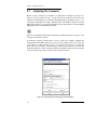
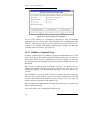
3.1.5
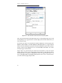
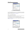
Reading Jaguar Input Files
Jaguar maintains its own input files, which include calculation options in addition to the
molecular geometry, and may also include molecular orbitals. In addition, Jaguar can read
a wide variety of input file types from other quantum chemistry codes, using the program
Babel. Therefore, Jaguar has a separate file reading mechanism. When you read input files
through Jaguar, the structures are displayed in the Workspace and Maestro-formatted files
are created.
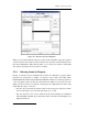
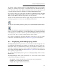
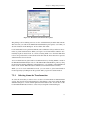
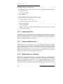
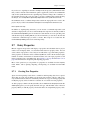
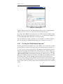
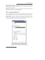
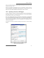
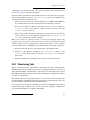
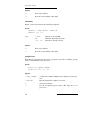
To read input files through Jaguar, choose Jaguar from the Applications menu, then click
Read in the Jaguar panel. The Read File file selector is displayed. Navigate to the directory containing the file, and select the file. Choose the file type from the File Format option
menu, and change the Read as setting if necessary. Click OK to read the file.
For more information, see the Jaguar User Manual. The full list of file types read by
Babel is included in that document.
22
Maestro 6.5 User Manual
Chapter 3: Importing and Exporting Structures and Data
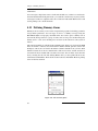
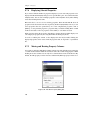
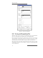
Figure 3.2. The Jaguar Read File file selector.
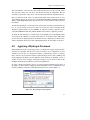
3.2
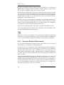
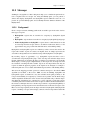
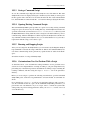
Exporting Structures
Using the Export panel, you can write out structure files in Maestro, MacroModel, PDB,
Sybyl Mol2, and MDL SD formats, and in various other formats available through the
program Babel. You can use the Workspace contents or selected project entries as input,
and you can append structures to an existing file and retain additional information when
the file format allows it. When exporting project entries, Maestro provides options for
exporting each selected entry to its own file, or placing all selected entries in the same file.
Project data is automatically saved, unless you are running in a non-automatic synchronization mode. The structures from a project are saved in a Maestro-formatted file, along
with other data. If you want to save just the structures and their associated data, or if you
want to save structures in other file formats, you can export the structures.
To open the Export panel, choose Export Structures from the Project menu on the main
menu bar, or choose Structures from the Export submenu of the Table menu in the Project
Table panel.
When you have made all the necessary selections, click Export. A dialog box confirms that
the files were written. If a file by the specified name already exists, the Exporting-Overwrite? dialog box is displayed and you must choose an action.
Maestro 6.5 User Manual
23
Chapter 3: Importing and Exporting Structures and Data
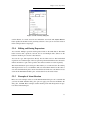
Figure 3.3. The Export panel.
3.2.1
Selecting Export Settings
The Export panel is laid out in a similar fashion to the Import panel, with the file and file
type selection tools at the top, and various options under them.
Selecting a file format: To create a file, you must select the type of file you wish to write
from the types given in the Format option menu, which include Maestro, MMOD (MacroModel), PDB, Mol2, SD, and a range of file types converted by Babel. The file extension in
most cases is determined by the file type. Default file extensions for the files in the first
section of the menu can be set in the File Suffix folder of the Preferences panel. Properties
from the Project Table are exported as well as structures to Maestro and SD files, and any
relevant properties are exported to PDB files.
Selecting a directory: To select a directory, you can enter it in the Path text box, navigate
to it in the Directories list, or click Launch Directory or Current Directory to select the
directory from which you launched Maestro or the current working directory. The path
and the directory and file lists are updated for the chosen directory.
24
Maestro 6.5 User Manual
Chapter 3: Importing and Exporting Structures and Data
Selecting a file: If the file exists, you can select it in the Files list or enter its name in the
File text box. If you want to export to a new file, enter the name in the File text box. You
can specify an absolute or relative path in the File text box in addition to the file name.
Appending or overwriting files: To append a structure to an existing file, select Append.
If the file exists and you do not select Append, it is overwritten.
Saving graphical information: If you are writing a Maestro file, you can select Save
Graphical Information to store the molecular representation information for the structure
you are saving. This option is ignored for other file types.
Specifying the source of the structures: The Export panel can be used to save structures
directly from the Workspace or to write out files containing structures associated with one
or more project entries. To write out the Workspace to a file, select Workspace in the
Structure Source To Be Exported section. This is equivalent to writing the included
entries. To use the entries that are selected in the Project Table as the content for the
exported file, select Selected Entries.
Exporting to single or multiple files: You can export entries to a single, multi-structure
file, or to multiple files that each contain a single entry. From the Files option menu,
choose either Export All Entries To A Single File or Export Each Entry As An Individual File.
If you export structures using one of the Babel-supported formats, you can only export a
single structure to each file. In this case, you should not choose Export All Entries To A
Single File.
3.2.2
Exporting Multiple Files
If you want to save each entry to a separate file, you must specify how to name the files by
choosing one of three naming schemes from the File Names Are option menu. The naming
schemes are described below.
File Name + Entry Name
If you choose File Name + Entry Name, you must select a file or type in a file stem. The
entry name and the file suffix are appended to the file stem. If you choose a file name, the
suffix is the suffix of that file name. For example, if you are exporting the entries
combination-3, combination-4, and combination-5 in Maestro format, and you
select the file structure.dat, the new files are named
structure_combination-3.dat
structure_combination-4.dat
structure_combination-5.dat
If you typed in the file stem HIV, the following files would be written:
Maestro 6.5 User Manual
25
Chapter 3: Importing and Exporting Structures and Data
HIV_combination-3.mae
HIV_combination-4.mae
HIV_combination-5.mae
File Name + Automatic Number
If you select File Name + Automatic Number, you must specify a filename. The files are
given the same name and extension as the selected file, but numbers are added in sequence
to the base file name. For the same example as above, if you select the file
structure.dat, the new files are named
structure_1.dat
structure_2.dat
structure_3.dat
Just Entry Names
If you choose Just Entry Names, the file name is constructed from the entry name. For the
above example, the new files are named
combination-3.mae
combination-4.mae
combination-5.mae
and a dialog box confirms that the files were written to the desired directory.
3.3
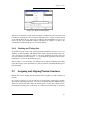
Exporting Data to a Spreadsheet
The Project Table does not have spreadsheet capabilities, but you can export data to a
spreadsheet file, manipulate it in a spreadsheet program, then re-import it into Maestro.
Exporting data to a spreadsheet file is done from the Export Spreadsheet panel. The data
that you can export are the properties in the Project Table. To export data, you must first
open Project Table panel, which you can do by choosing Show Table from the Project
menu in the main window or clicking the Show/Hide project table button in the toolbar.
When the Project Table panel is displayed, choose Spreadsheet from the Export submenu
of the Table menu. The Export Spreadsheet panel is displayed. The layout of this panel is
similar to that of the Export and Import panels, with file selection tools at the top and
action buttons at the bottom.
Selecting a directory: To select a directory, you can enter it in the Path text box, navigate
to it in the Directories list, or click Launch Directory or Current Directory to select the
26
Maestro 6.5 User Manual
Chapter 3: Importing and Exporting Structures and Data
directory from which you launched Maestro or the current working directory. The path
and the directory and file lists are updated for the chosen directory.
Selecting a file: If the file exists, you can select it in the Files list or enter its name in the
File text box. If you want to export to a new file, enter the name in the File text box. You
can specify an absolute or relative path in the File text box in addition to the file name.
Existing files will be overwritten.
Selecting entries to export data from: The Entries option menu allows you to choose
different classes of entries to export data from: All, Shown, Selected, and Included. For
more information on showing, selecting, and including entries, see Section 8.4 on page 85
and Section 8.5 on page 89.
Selecting properties to export: You can choose to export all properties or only the shown
properties, using the Properties option menu. The row number and the inclusion state are
not exported, but all other properties are. The entry name is always in the first column.
Selecting a delimiter: You can choose from the two standard delimiters, a comma and a
tab character, or choose other, then enter your own delimiter in the text box.
Once you have made your selection, click Export. The file is written and its name is
displayed in the Files list.
Figure 3.4. The Export Spreadsheet panel.
Maestro 6.5 User Manual
27
Chapter 3: Importing and Exporting Structures and Data
3.4
Importing Data from a Spreadsheet
Once you have exported data from Maestro and manipulated it in a spreadsheet, you can
re-import the data into Maestro. You can also import data that did not originate from
Maestro. Importing data from a spreadsheet file is done from the Import Spreadsheet
panel, and the data is added to entries in the Project Table. The data that you import must
therefore match entries in the project. For data that you exported from Maestro, matching
should be no problem, but for data that did not originate from Maestro, you must ensure
that there is a proper match to the entries in the Project Table.
To import data, you must first open Project Table panel, which you can do by choosing
Show Table from the Project menu in the main window or clicking the Show/Hide project
table button in the toolbar.
When the Project Table panel is displayed, choose Spreadsheet from the Import submenu
of the Table menu. The Import Spreadsheet panel is displayed. The layout of this panel is
similar to that of the Export and Import panels, with file selection tools at the top and
action buttons at the bottom.
To select a file to import data from, you can navigate to it with the file selection tools, or
enter its name in the File text box.
Figure 3.5. The Import Spreadsheet panel.
28
Maestro 6.5 User Manual
Chapter 3: Importing and Exporting Structures and Data
Figure 3.6. The Choose Import Key dialog box.
When you have selected the file, click Import. The Choose Import Key dialog box is
displayed. In this dialog box, you determine how the rows of the spreadsheet are mapped
to the entries in the Project Table, and select the delimiter. The File key column lists the
properties in the spreadsheet file. The values of the key that you choose in this column are
matched to the values of the property that you choose in the Match to property in Project
Table column. For example, if both the spreadsheet and the Project Table have a Title
property, you can match the rows by title. If the file key value for a given row in the
spreadsheet matches more than one entry, the properties for that row are copied to all
entries; if several file key values match a single entry, the row for the last file key value
that matches is used to import data.
To complete the import, choose the delimiter that is used in the spreadsheet file, then click
OK. The values in the spreadsheet are imported into the Project Table.
Maestro 6.5 User Manual
29
Chapter 3: Importing and Exporting Structures and Data
30
Maestro 6.5 User Manual
Chapter 4:
Building Structures
Maestro provides a variety of tools for building and modifying structures. In the Build
panel, you can create molecular structures from predefined fragments or from individual
atoms, and modify structures and atom and residue properties. Other panels enable you to
add hydrogen atoms, adjust the geometry, connect or fuse molecules, and define centroids
of groups of atoms. You can also set preferences for the behavior when certain building
tasks are performed in the Preferences panel.
Some of the operations for building and modifying structures involve selection of atoms in
the Workspace. For information on selecting atoms, see Chapter 5.
4.1
The Build Panel
The Build panel consists of a toolbar and three tabbed folders. The primary building tools
are contained in the Fragments folder and the toolbar. The Fragments folder contains
several fragment libraries from which you can select a fragment and add it to the Workspace, either by positioning it manually or by using predefined grow rules. The other two
folders, Atom Properties and Residue Properties contain tools for changing the properties
of atoms or residues.
To open the Build panel, choose Build from the Edit menu, or click the Show/Hide Build
panel button on the main toolbar.
The Fragments folder is displayed by default.
The toolbar of the Build panel provides quick access to tools for drawing and modifying
structures and labeling atoms. See Section 2.3.1 on page 7 for a description of the types of
toolbar buttons. The toolbar buttons are described below, and their use is described later.
Draw
Draw structures freehand in the Workspace. Menu button with a list of elements to draw
with (default C). Each click in the Workspace places an atom and connects it to the previous atom.
Delete
Choose an object to delete. Menu button with a pick menu and other items. Same as the
Delete button on the main toolbar.
Set element
Pick atoms to change to the selected element (default C). Menu button with a list of target
elements. Menu button with a limited list of target elements.
Maestro 6.5 User Manual
31
Chapter 4: Building Structures
Increment bond order
Pick a bond to increase its bond order by one, to a maximum of 3.
Decrement bond order
Pick a bond to decrease its bond order by one, to a minimum of 0.
Increment formal charge
Pick an atom to increase its formal charge by one.
Decrement formal charge
Pick an atom to decrease its formal charge by one.
Move
Pick an atom to move in the xy plane or the z direction. Menu button with a list of drections. Moves in the xy plane are made by clicking the new location. Moves in the z direction are made in 0.5 Å increments.
Label
Apply heteroatom labels as you build a structure. The label consists of the element name
and formal charge, and is applied to atoms other than C and H.
Display Connect/Fuse panel
Open the Connect & Fuse panel so you can connect structures (create bonds between
structures) or fuse structures (replace atoms of one structure with those of another).
Display Adjust panel
Open the Adjust panel so you can change bond lengths, bond angles, dihedral angles, or
atom chiralities. By default, the Dihedral folder is displayed.
Add hydrogens
Pick to apply the current hydrogen treatment. Menu button with a pick menu and an item
to open the Atom Selection dialog box. Same as the Add hydrogens button on the main
toolbar.
4.2
Building a Structure From Fragments
Whenever possible, you should use fragments to build structures. Building from fragments
ensures the correct geometry within each fragment, and thereby reduces the work needed
to minimize the structure. The following fragment libraries are available with Maestro:
•
•
•
•
•
•
32
Organic
Rings
N-heterocycles
O-heterocycles
S-heterocycles
Mixed heterocycles
•
•
•
•
•
•
L carbohydrate pyranose
Metal centers
Metal ligands
Amino acids
Nonstandard amino acids
Protein capping groups
Maestro 6.5 User Manual
Chapter 4: Building Structures
• Carbohydrate furanose
• Carbohydrate pyranose
• L carbohydrate furanose
• Deoxyribonucleic acids
• Ribonucleic acids
These libraries are described briefly below.
• Organic—This library contains the common organic functional groups, a selection
of simple ring structures, some common ions such as hydroxide, sulfate, nitrate,
ammonium, and a hydrogen molecule.
• Rings—This library contains some more complex ring structures than those in the
organic fragments library, including some fused ring structures, a basic steroid structure, porphyrin and phthalocyanine, buckminsterfullerene, and dodecaborane.
• Heterocycles—The four heterocycle fragment libraries provide a range of ring structures that contain nitrogen, oxygen, and sulfur atoms.
• Furanose and pyranose structures—Sugars can assume cyclized forms that
include either five or six members. The five-membered ring form is called the furanose form, and the six-membered version is called the pyranose form. The natural
state of most sugars is the pyranose form, but some derivatives assume a furanose
form. Maestro provides both options in both D and L forms.
• Metal centers and ligands—These libraries contain common ligands used in inorganic chemistry and metal centers with various coordination numbers, but with the
specific metal undefined. To change the metal type, retype the center once it is placed
in the Workspace, using the Elements menu option in the Atom Properties folder.
• Amino acids—The Amino acids library contains the 22 naturally-occurring amino
acids. The Nonstandard amino acids library includes the D forms of the 22 naturallyoccurring amino acids and various other residues.
• Nucleic acids—The Deoxyribonucleic acids library contains Adenosine, Cytosine,
Guanine, and Thymine, while the Ribonucleic acids library contains Adenosine,
Cytosine, Guanine, and Uracil.
• Protein capping groups—This library contains some common molecules used to
cap peptides.
To select a fragment library, choose the library from the Fragments option menu. The area
below this menu contains a grid of buttons that you use to select fragments. Each button
displays either the name of the fragment, an abbreviation for the fragment name, or the
fragment structure. If a structure is displayed, the name of the fragment is given in the
Balloon help for the button.
Maestro 6.5 User Manual
33
Chapter 4: Building Structures
Figure 4.1. The Fragments folder of the Build panel, showing the Organic library.
If the particular fragment you want to use is not in the supplied libraries, you can build it
from other fragments, or select a fragment with a geometry similar to the one you want to
use, then replace atoms with those of different elements from the Atom Properties folder.
The fragment libraries and grow rules are read and interpreted at run time. If you are interested in creating your own fragments or fragment libraries, please write to [email protected] to obtain the appropriate instructions.
4.2.1
Building Structures Using Place Mode
You can use Place mode to create multiple molecular structures in the Workspace, to
assemble structures from multiple fragments, and to change a fragment into another fragment within a structure. To enter Place mode, select Place in the Fragments folder.
To create multiple structures in the Workspace in Place mode, choose a library from the
Fragments option menu, select a fragment, and click in the Workspace. Repeat this
process, clicking in a different place in the Workspace for each new fragment you want to
place. The fragments are placed in a predefined orientation at the location you select, and
are completed with hydrogen atoms to form molecules.
34
Maestro 6.5 User Manual
Chapter 4: Building Structures
Figure 4.2. The Fragments folder of the Build panel, showing the Mutate option.
If you want to join these structures to form a single molecule, you can use the tools in the
Connect/Fuse panel. See Section 4.6 on page 40 for details.
You can build a single structure from multiple fragments in Place mode. Once you have
placed the first fragment, you can join a second fragment to it by selecting the fragment
from the fragments list and clicking in the Workspace on the atom that you want the new
fragment to replace. If you click on a terminal atom, the fragment replaces the terminal
atom. If you click on a non-terminal atom, that atom and its attached hydrogen atoms are
replaced by the new fragment. For example, clicking on a secondary amine nitrogen with a
methyl fragment gives a disubstituted methyl center, and clicking on a disubstituted
methyl carbon with an amine fragment produces a secondary amine center.
You can also mutate one residue into another in a protein. When you select Amino acids
from the Fragments menu, a Mutate button appears beside the Define grow bond picking
tools. To mutate a residue, select Mutate, select the new residue from the list and pick an
atom in the residue you want to mutate. The new residue replaces the old residue.
Maestro 6.5 User Manual
35
Chapter 4: Building Structures
4.2.2
Building Structures Using Grow Mode
In Grow mode you can take advantage of the predefined “grow” rules that dictate where
and how fragments are connected to build structures. To enter Grow mode, select Grow in
the Fragments folder.
To create a structure in Grow mode, click the fragments in the fragment library that you
want to assemble in the Workspace. At each click, the selected fragment is added to the
structure, and a green arrow marks the location of the grow bond—the bond that will be
replaced when the next fragment is added.
To grow a structure from a location other than that indicated by the current grow bond, you
can choose a new grow bond using one of the following methods:
• Choose Atom from the Pick menu of the Define Grow Bond section, and pick two
atoms in the order that defines the grow direction.
• Choose Bond from the Pick menu of the Define Grow Bond section, and pick a bond.
The grow direction arrow points to the atom closest to where you click.
• Choose backward from the Grow Direction option menu. The grow bond moves to the
opposite end of the molecule.
In addition to the fragments, the Fragments folder of the Build panel contains controls for
setting the joining geometry, and, where applicable, secondary structure and helix geometry. The Joining Geometry option menu provides context-sensitive options for attaching
new fragments to the existing structure. For example, under the Deoxyribonucleic acid
fragment type, the joining geometry options are Standard Helix and User Defined.
If you choose to define your own joining geometry, you must specify values for the
torsions that define applicable secondary and tertiary structures. When you select the User
Defined option and click on the name of the fragment, a dialog box prompting you to enter
an angle value is displayed. Enter a value and click OK.
4.3
Building a Structure From Atoms
The toolbar of the Build panel contains tools for drawing structures in the Workspace atom
by atom, and the Atom Properties folder and the toolbar contain tools for retyping atoms
within a structure. Maestro does not automatically correct geometries of structures created
in Draw mode. You can adjust the geometry after building the structure from the Adjust
panel. You should also minimize the energy of the completed structure.
When using Draw mode to create a molecular structure, only a few elements—H, C, N, O,
P, and S—are available. If you want to include different elements, use these elements to
draw the structure, and then change the desired atoms—see Section 4.4. Maestro allows
36
Maestro 6.5 User Manual
Chapter 4: Building Structures
you to violate the valency of an atom in Draw mode so that you can change it to an atom of
some other element.
The basic operations of Draw mode are described below.
• To begin drawing with the currently selected element, click the Draw button.
The Draw button appears indented, indicating that you are in Draw mode. The
default element is carbon.
• To place an atom, click in the Workspace.
The atom appears as an asterisk enclosed in a purple cube. The cube indicates that
the atom is active, which means that it will be automatically connected to the atom
that is placed next. Each subsequent click in the Workspace places another atom and
bonds it to the previous atom with a single bond. To finish drawing, click the active
atom. The cube vanishes.
• To start drawing from another location in the structure, deactivate the active atom by
clicking on it, then click on the atom that you want to start drawing from. This atom
becomes the active atom.
• To connect the active atom to an existing atom, click the existing atom.
• To create a multiple bond between the active atom and an adjacent atom, click the
adjacent atom. Another bond is added between the two atoms.
• To change the element that you are drawing with, select the element from the Draw
button menu. The next new atom you place will be an atom of the new element. If
you connect existing atoms of a different element, the element of the existing atom is
not changed: thus, it does not matter which element is selected when you draw a
bond between two existing atoms.
The atoms that you draw are placed in the x-y plane. If you want to create a 3D structure,
you can rotate the structure in the Workspace with the middle mouse button, then continue
drawing atoms. Rotation does not change the active atom or exit Draw mode. You can also
move atoms that you have placed using the Move button menu.
To move an atom in the x-y plane, choose X-Y from the button menu, click the atom you
want to move, then click the new location. If the atom is in a ring, only the atom is moved.
If the atom is not in a ring, the atom and its attached atoms are moved. To move an atom in
the z direction, choose +Z or -Z from the menu, and click the atom to be moved. The atom
is moved 0.5 Å in the chosen direction.
Maestro 6.5 User Manual
37
Chapter 4: Building Structures
4.4
Changing Elements
Whether you build a molecule in Place mode, Grow mode, or Draw mode, the range of
elements available to you is limited. To include other elements in your structure, you must
first build with existing elements, then change the element to another element in the appropriate locations in the structure. You do not have to complete the structure before you
make the change, you only have to place an atom at the desired location.
Changing an atom from one element to another can be done from the Build panel toolbar
or from the Atom Properties folder. From the Set Element button menu in the toolbar
you can choose an element from H, C, N, O, P, or S, then click on an atom in the Workspace to change it to the selected element.
If you want to change an atom to some other element, choose Element from the Property
menu in the Atom Properties folder. A periodic table is displayed, from which you can
select an element, then click on an atom in the Workspace to change it to that element. You
do not need to select Set Element: this is done automatically when you click on an
Figure 4.3. The Atom Properties folder showing tools for the Element property.
38
Maestro 6.5 User Manual
Chapter 4: Building Structures
element. However, you can select Set Element if it is unselected and you want to use the
currently selected element.
4.5
Changing the Bond Order and Formal Charge
After creating a structure using the tools in the Build panel, you may wish to change some
of the bond orders or formal charges. Tools for making these changes are available on the
Build panel toolbar.
To increase the bond order, click the Increment bond order toolbar button
then click the bonds whose order you want to increase. Each click increments the bond
order by one, up to a maximum of three. You can also increase the bond order in Draw
mode by drawing another bond between the two atoms.
To decrease the bond order, click the Decrement bond order toolbar button
then click the bonds whose order you want to decrease. Each click decrements the bond
order by one, to a minimum of 0. Zero-order bonds are displayed with a green line.
When you change the bond order, the valence states of the atoms can be violated. Maestro
gives no warning of this violation, so it is up to you to ensure that your structure is valid.
To increase the formal charge, click the Increment formal charge toolbar button
then click the atoms whose formal charge you want to increase. You can only increase the
formal charge one atom at a time. However, the formal charge is also set when you change
the MacroModel atom type.
To decrease the formal charge, click the Decrement formal charge toolbar button
then click the atoms whose formal charge you want to decrease. Like increasing the
formal charge, you can only decrease the formal charge one atom at a time, and the formal
charge is set when you change the MacroModel atom type.
Maestro 6.5 User Manual
39
Chapter 4: Building Structures
4.6
Fusing or Connecting Structures
To build some structures, it is sometimes convenient to connect or to fuse two existing
structures. Connecting two structures creates a new bond between two selected atoms,
with deletion of appropriate hydrogens. An example is the creation of bipyridyl from two
pyridine rings, by connecting the 2-carbon on one ring with the 5-carbon on the other, and
deleting the hydrogen atoms. Fusing two structures deletes atoms. An example is the
fusion of two benzene rings, in which two carbon and two hydrogen atoms are deleted
from one ring, and bonds formed to the other ring with deletion of two hydrogen atoms.
The tools for fusing and connecting structures are available from the Connect & Fuse
panel. In the connection and fusion operations, an attempt is made to create structures with
reasonable geometries, and a check is made that valency is not violated. This is in contrast
to Draw mode, which does not evaluate bonding or geometry.
For both connect and fuse operations, you must first select atom pairs to be joined. The
atoms you select must not be hydrogen atoms. You can select as many pairs as you like.
The first atoms in all selected pairs must all come from the same molecule, and the second
atoms in the pairs must come from the same molecule. The molecule for the set of first
atoms set need not be different from the molecule for the set of second atoms. If you select
a pair of atoms in the same molecule, a new bond is drawn between the atoms.
To select atoms for a connect or fuse operation, ensure that Pick to define atom pairs is
selected and click on the Workspace atoms to define the pairs. Atom numbers of the
selected pairs appear in the Connect or fuse atoms list. Also, if Show Markers is selected,
each pair is marked with a dashed green line. For the pair that is selected in the list, the
green line is flanked by solid yellow lines. The lines disappear once the connect or fuse
operation is completed.
Figure 4.4. The Connect & Fuse panel.
40
Maestro 6.5 User Manual
Chapter 4: Building Structures
When fusing structures, the order in which you select the atom pair is important. The atom
selected first replaced by the second selected atom. For example, when fusing an amino
nitrogen and an ethyl carbon, selecting the nitrogen first results in its deletion, followed by
attachment of the remaining atoms of the amine to the ethyl carbon. Selecting the ethyl
carbon first results in deletion of the carbon and retention of the nitrogen.
To delete an atom pair from the Connect or Fuse Atoms list and cancel the connection or
fusion of those atoms, select the pair in the list and then click Delete. To clear the atom
pair list, click Delete All.
When you have selected all the pairs of atoms that you want to connect or fuse, click the
appropriate button—Connect or Fuse.
If you are performing a connection or fusion between structures belonging to different
project entries (the source entries), the result must belong to a single entry. When you
click Connect or Fuse, the Choose Entry dialog box is displayed, and you must specify the
entry with which the new structure should be associated. Subsequent actions depend on
which entry you choose:
• If you choose one of the two source entries, the other entry is deleted.
• If you choose an existing entry other than the two source entries, the new structure is
added to the existing entry and the source entries are deleted.
The Choose Entry dialog box provides some tools for selecting the destination
entry: a menu to limit the entries listed, and some sort options.
• If you provide a new entry name in the Name text box, the source entries are deleted,
and a new entry is created that contains the fused or connected structure.
You can undo a connect or fuse operation, and the changes to the entries are also undone.
Figure 4.5. The Choose Entry dialog box.
Maestro 6.5 User Manual
41
Chapter 4: Building Structures
4.7
Adjusting the Geometry
Before you use a structure for a calculation, you might want to adjust the geometry, especially if you have used Draw mode, or if the Grow mode orientation was incorrect. In
addition to the adjustments you can make with the Move button, described on page 37, you
can change bond lengths, bond angles, dihedral angles, and chirality using the tools in the
Adjust panel, which you open from the Edit menu in the main window or with the Display
Adjust panel button on the Build panel toolbar.
The tools for adjusting bond lengths, bond angles, and dihedral angles are similar, so the
description given here is generic.
To define the geometric parameter that you want to adjust, choose Atoms or Bonds from
the Pick menu in the Define atoms for operation section, and pick the atoms or bonds. For
a bond length, you must pick two atoms or one bond; for a bond angle, you must pick
three atoms or two bonds; for a dihedral angle you must pick four atoms or one bond—the
bond about which the rotation is performed. When you pick this bond, the groups attached
to the atom nearest the point you click are the ones that are moved.
Figure 4.6. The Adjust panel, showing the Dihedral folder.
42
Maestro 6.5 User Manual
Chapter 4: Building Structures
The atom numbers of the selected atoms are listed in the text box at the top of the folder.
You can pick as many sets of atoms as you like before doing any adjustments. The last
atom that you pick is the “target atom”—the atom that is moved in the adjustment process.
Once you have chosen the atoms, you must decide which of the attached atoms to move
along with the target atom. You can choose from All Attached Atoms, All Attached Terminal
Atoms, or Only Single Atom. If the target atom is part of a ring, the first of these options is
unavailable.
To make the adjustment, you can enter a new value for the geometric parameter in the text
box, or you can use the mouse. If you enter a new value, the value is changed and the
Workspace updated when you press ENTER. To adjust the geometry using the mouse,
select Allow Adjustment then drag with the middle mouse button to adjust the geometry.
To adjust the stereochemistry at a chiral center, use the picking tools in the Chirality folder.
You can invert the chirality of selected chiral centers or of all chiral centers. This folder
also has buttons for displaying the R and S labels for the configuration at chiral centers,
and for clearing the labels. If you click Label Chiral Centers, all other labels are cleared.
4.8
Applying a Hydrogen Treatment
When building molecules or preparing proteins, you might want to apply a hydrogen treatment that is compatible with the force field you intend to use in calculations on those
structures. You can also use a hydrogen treatment to add hydrogen atoms to a structure
that is used for any program that requires explicit hydrogen atoms, such as QikProp and
Jaguar. Hydrogen treatments can treat hydrogen atoms explicitly or implicitly, as part of
another atom. To select and apply a hydrogen treatment, you can use the controls in the
Hydrogen Treatment panel, which you open from the Edit menu.
To select a hydrogen treatment, choose an option from the Treatment option menu. A
description of the treatment is displayed in the Description text box, including the force
fields for which the treatment is valid. This information is also given in Table 4.1.
Figure 4.7. The Hydrogen Treatment panel.
Maestro 6.5 User Manual
43
Chapter 4: Building Structures
All-atom with Osp3-Lp
Csp3 United-atom with
S-Lpa
Csp2/sp3 United atom
with No-Lpa
X
X
X
OPLS
OPLS-AA,
OPLS2001
X
X
X
Csp3 United-atom with
No-Lpa
All atom with S-Lp
MMFFS
X
MMFF
X
AMBER94
MM2
All-atom with No-Lp
AMBER
Hydrogen Treatment
Method
MM3
Table 4.1. Appropriate hydrogen treatments for Maestro-supported force fields.
X
X
X
a. In a united atom representation, hydrogen atoms are incorporated into the dimensions of the
heavy atom to which they are attached. That is, they are implicit.
You can apply the selected treatment to the entire structure or to selected parts of the structure. To apply the treatment to the entire structure click All in the Modify Hydrogen Treatment section. To apply the treatment to selected atoms, use the picking tools in the Modify
Hydrogen Treatment section or click Select to open the Atom Selection dialog box and
define the selected atoms. If the structure already complies with the treatment you
selected, no changes will be made when you click Apply Current Treatment To All Atoms.
You can also apply the current hydrogen treatment to selected atoms, molecules, residues,
chains, or entries from the main toolbar or the Build panel toolbar. Select one of these entities from the Add hydrogens button menu,
then click on atoms in the Workspace to apply the treatment. Double-click this button to
apply the treatment to all atoms in the Workspace.
Each time you select a force field in the Potential section of a MacroModel or Impact
energy panel, the hydrogen treatment is automatically changed to comply with that force
field, and the hydrogen treatment for any atoms you subsequently draw in the Workspace
will have the new hydrogen treatment. If you attempt to start a MacroModel, Impact, or
Jaguar job using an input structure with an incompatible hydrogen treatment, the job fails.
44
Maestro 6.5 User Manual
Chapter 4: Building Structures
4.9
Changing Atom Properties
In addition to changing the element and the formal charge, you can change a variety of
other atom and residue properties. The tools for making changes are in the Atom Properties folder. Each choice of property from the Property menu displays a set of tools that you
can use to change the property. Apart from the Element property, the properties are listed
below with a description of the tools. Before you change atom properties, it may be
helpful to display atom labels. For atom labeling information, see Section 6.3 on page 67.
Atom type (MacroModel)
A list of atom type symbols with a brief description is displayed. The atom type symbols
represent atoms with specific properties, such as sp3 hybridization for a C atom with type
symbol C3, or a free radical for a C atom with type symbol CR. The use of atom types is
provided primarily for MacroModel users, though Maestro always assigns an atom type to
each atom. For information on atom types, see Appendix B. To retype an atom, choose the
atom type and click on the atoms in the Workspace that you want to change.
Figure 4.8. The Atom Type (MacroModel) tools in the Atom Properties folder.
Maestro 6.5 User Manual
45
Chapter 4: Building Structures
Figure 4.9. The Partial Charge tools in the Atom Properties folder.
Partial Charge
To apply new partial charges to atoms of interest, enter new charges in the Partial Charge
and Solvation Charge text boxes, and use the picking tools to apply the partial charges to
the atoms of interest. Both of these charges are used in MacroModel calculations. The
solvation charge is used in MacroModel GB/SA solvation calculations. Generally, these
two values should be the same. Default values for these charges are supplied with MacroModel force fields. You can also use partial charges from Jaguar electrostatic potential
calculations, which are read by default when the results Jaguar calculations are incorporated or imported.
PDB Atom Name
A PDB atom name is a combination of a chemical symbol and a connection indicator. The
first two characters contain the element symbol, right-justified; the third character is a
remoteness indicator (A=alpha, B=beta, G=gamma, and so on), and the fourth, if it is
needed, is a numeric branch designator. For instance, the name “_CA_” represents an
alpha carbon, “_CB_” a beta carbon, and “_HB_” a hydrogen on a beta carbon. In these
descriptions, the underscore characters represent spaces, which are required for compliance with PDB semantics: “CA__” is a calcium atom, and is different from “_CA_”.
46
Maestro 6.5 User Manual
Chapter 4: Building Structures
Figure 4.10. The PDB Atom Name tools in the Atom Properties folder.
Occasionally, when reading or writing a PDB file, Maestro is not able to assign PDB
names to all the atoms. To manually apply missing PDB atom names, enter the desired
name in the PDB atom name text box and use the Apply PDB atom name picking tools to
select the atoms to which you want to apply the name.
For some purposes, such as for ligands in Prime induced fit calculations, it is useful to
have unique atom names within residues. To make the atom names unique, use the Set
unique PDB atom names within residues picking tools. The unique names are composed
of the element symbol, right justified in the first two characters, followed by a numeric
index for that element.
Grow Name
This name is the name used internally for a fragment when growing a structure. The
intended use of this property is labeling new fragments for a fragment library.
Atom Name
You can assign one of three types of names to atoms in the Workspace: user-specified,
canonical, or unique. User-specified names can be any length. To assign a user-specified
Maestro 6.5 User Manual
47
Chapter 4: Building Structures
Figure 4.11. The Atom Name tools in the Atom Properties folder.
name, type the desired name in the Atom name text box of the Set atom name section, and
use the picking tools to apply the name. You must display the atom name labels before you
can see the new name.
A canonical atom name is an automatically assigned combination of atom property pairs:
Element & Atom Number or Residue Number & PDB Atom Name. To assign canonical
names, select the desired pair of properties from the Composition option menu, specify a
separator symbol in the Separator text box, and click Apply To All Atoms. You cannot
selectively apply canonical names.
Unique names are generated using the element and atom number of each atom. If this
naming scheme produces atoms with identical names, Maestro adds numeric suffixes,
followed by tilde (~) symbols to distinguish the names. To apply unique names to all
atoms, click Make Unique in the Modify existing names section. As for canonical names,
you cannot selectively apply unique names.
48
Maestro 6.5 User Manual
Chapter 4: Building Structures
4.10 Changing Residue Properties
Residue properties can be changed in the Residue Properties folder. This folder is laid out
in a similar fashion to the Atom Properties folder, with a Property menu and a set of tools
displayed for each choice. The residue properties and their tools are described below. In
order to view the results, you must first display the appropriate atom labels.
Residue Number
To renumber residues, in the Renumber Residues section enter the starting value in the
Renumber From text box, then use the picking tools to select the residues to renumber.
Renumbering a single residue is the same as assigning its number. To apply a specific
number to one or more residues, in the Apply residue number section enter the number
you want to apply in the Residue number text box, then use the picking tools to select the
residues to apply the number to.
Residue Name
To name residues, enter the residue PDB name in the Residue PDB name text box, and use
the picking tools to select the residues to name.
Figure 4.12. The Residue Number tools in the Residue Properties folder.
Maestro 6.5 User Manual
49
Chapter 4: Building Structures
Chain Name
You can assign a single-letter name to chains. The definition of a chain is not restricted to
the items labeled Chain in the pick menus: you can define a chain in any way that you like,
and assign it a name. To assign the name, enter a character in the Chain Name text box and
use the picking tools to define the chain.
4.11 Defining Dummy Atoms
Dummy atoms are used by several of the computational programs for defining geometries
and geometric parameters. You can retype an atom to a dummy atom type using the
MacroModel Types atom property described earlier. You can also place a dummy atom at
the centroid (mean position) of a group of atoms, such as a ring. You can then change the
dummy atom to a real atom, and thus place real atoms at the centroid of some system of
interest.
The centroid capability is available in the Centroids panel, which you open from the Build
menu. To define a centroid, select Pick atoms to define centroid, pick the atoms in the
Workspace. The atoms are listed in the Atoms to define centroid list. If you have Show
markers selected, the atoms are marked with a salmon-colored star, and the atom that is
selected in the list is marked with a lavender-colored star. You can delete atoms from the
list by selecting the list item and clicking Delete. Once you have picked all the atoms,
click Create Centroid Atom. The To define another centroid, click Delete All before picking
atoms for the new centroid.
Figure 4.13. The Centroids panel.
50
Maestro 6.5 User Manual
Chapter 4: Building Structures
4.12 Deleting Atoms
If you need to delete atoms from a structure, you can use the Delete button menu on either
the main toolbar or the Build panel toolbar.
This menu offers choices for the type of object to delete, and allows you to open the Atom
Selection dialog box to select atoms for deletion based on their properties.
When you delete atoms, the terminal atoms that are attached to this atom can be deleted,
or the terminal atoms can be left in place. Terminal atoms are atoms that are bonded only
to that atom, such as hydrogen or a halogen. Deleting terminal atoms would not, for
example, delete a methyl group attached to the deleted atom. This action is controlled by
an option that you can set in the Builder folder of the Preferences panel.
If you want to delete all atoms in the Workspace, use the Clear Workspace button, which
is located on the main toolbar.
Maestro 6.5 User Manual
51
Chapter 4: Building Structures
52
Maestro 6.5 User Manual
Chapter 5:
Selecting Atoms
Maestro has a powerful set of tools for selecting, or picking, atoms in a Workspace structure that takes advantage of chemical information about the structure. These picking tools
are embedded in each panel in which you need to select atoms to apply an operation. The
picking tools in a panel can include one or more of a Pick menu, an All button, a Select
button, which opens the Atom Selection dialog box, an ASL text box, a Clear button, and a
Show markers option. ASL stands for Atom Specification Language, and is described in
detail in the Maestro Command Reference Manual. Pick menus are also included in some
toolbar button menus.
The range of picking tools available in a panel varies according to the types of structural
unit that are needed for the operation and to whether picking causes immediate action or
requires an action to be specified later. The ASL text box and Clear button are included
only when picking merely defines a set of atoms for later use. For example, the Label
Atoms section of the Atom Labels panel has a Pick menu, an All button and a Select button,
and the action is immediate. The Sets panel has a full set of picking tools, and stores the
atoms in a defined set that can be used later.
5.1
The Pick Menu
The simplest form of atom selection involves selection of an object from a Pick menu and
clicking on an atom or a bond in the Workspace. The object can be one of atoms, bonds,
chains, residues, molecules, or entries. The number of objects available in the menu
depends on the operation. For instance, when you define a dihedral angle, you can pick
either four atoms or three bonds. The Pick menu for this operation therefore only contains
the items Atoms and Bonds.
Figure 5.1. Examples of picking tools. Top: from the Sets panel; Center: from the Atom
Labels panel; Bottom: from the Adjust panel.
Maestro 6.5 User Manual
53
Chapter 5: Selecting Atoms
Figure 5.2. The Sets panel, showing the pick menu.
The object you choose determines the atoms that are selected when you click on an atom
in the Workspace. A click on a single atom in the Workspace can represent the selection of
just that atom, or the selection of the molecule, residue, chain, or entry of which it is a
member. Successive clicks add atoms to the selection. If the object is Bonds, the two
atoms that define the bond are selected when you click on the bond.
When an object is selected, the cursor in the Workspace appears as a box, and the object is
indicated by a letter appearing under the cursor box. The letters A, B, R, C, M, and E
represent, in order, Atoms, Bonds, Residues, Chains, Molecules, and Entries.
You do not need to select the Pick button before choosing an item from the Pick menu.
Choosing an item automatically selects the Pick button.
5.2
The Atom Selection Dialog Box
If you want to make atom selections based on more complex criteria, such as selecting all
the carbon atoms in a protein backbone, you can use the Atom Selection dialog box. The
Atom Selection dialog box allows you to select atoms by defining complicated ASL
expressions without the need to understand the ASL syntax.
To open the Atom Selection dialog box, click Select in the relevant section of any panel.
The Atom Selection dialog box is modal: you must dismiss it before you can perform any
other operations, with the exception of rotation and translation of structures in the Workspace, and picking. The features of the dialog box are described below.
54
Maestro 6.5 User Manual
Chapter 5: Selecting Atoms
Figure 5.3. The Atom Selection dialog box.
When you are satisfied with the selection you have made, click OK to apply the operation
you have chosen to the selection you have made. Some operations, such as deleting atoms,
take effect immediately. Others merely define a set of atoms to be used in a subsequent
task, such as selecting atoms for creation of a surface.
5.2.1
Selecting Atoms by Property
Groups of atoms that can be included in the selection are defined by a property. These
properties are grouped into a number of categories, each in their own folder: Atom,
Residue, Molecule, Chain, Entry, Substructure Notation and Set. For each category there is
a list of properties shown on the left of the folder, from which you can select one item.
When you select an item, tools specific to that property are displayed in the center of the
folder. The three types of tools are:
• Text box. You can specify the allowed values for the property by using lists of numbers, closed ranges (e.g. 12-42) and open ranges (e.g. >= 30).
• List. You can choose one or more entries from the list by clicking, in combination
with the SHIFT and CTRL keys. Only items that are currently in the Workspace are
displayed in the list.
Maestro 6.5 User Manual
55
Chapter 5: Selecting Atoms
• Set of options, which can be nested. You can choose only one of the possible combinations by selecting the options.
For the first two tool types, you can also select items by picking in the Workspace. For
example, if you choose the Element property in the Atom category, then picking a carbon
atom in the Workspace selects the “C” item in the list of elements.
If Show Markers is selected, the atoms that are selected by the definition of a property and
its allowed values are marked in purple in the workspace. After each selection, these
markers are updated, and the value in the Atoms Matching field is updated to report how
many atoms are matched by the current property specification.
5.2.2
Combining and Modifying Atom Selections
When the selection is complete, you can combine it with the previous selection. The Add,
Subtract and Intersect buttons combine the ASL expression for the current selection with
the existing ASL expression in the ASL text box, as follows:
• The Add button includes the current selection in the existing selection by performing
a boolean OR operation on the ASL expressions.
• The Subtract button excludes the current selection from the existing selection by performing a boolean AND NOT operation on the ASL expressions.
• The Intersect button restricts the selection to the atoms that are in both the current
selection and the existing selection by performing a boolean AND operation on the
ASL expressions.
In addition to combining ASL expressions to form a new selection, you can negate an
entire expression with the Invert button, select all atoms with the All button, and clear the
ASL expression with the Clear button.
If Show Markers is selected, the atoms corresponding to the expression in the ASL text
box are highlighted with light blue markers in the workspace.
5.2.3
Selecting Atoms by Proximity
Once you have made an initial selection, you can select atoms based on their distance from
the atoms defined by the current ASL expression (the source atoms) in the Proximity dialog
box. To open this dialog box, click Proximity.
You can specify the distance in angstroms or in terms of the number of bonds. If the
boundary for inclusion intersects a molecule or a residue, you can choose to include the
entire molecule or residue using the Fill buttons. You can either include or exclude the
source atoms in the selection. For example, you might want to include residues within a
56
Maestro 6.5 User Manual
Chapter 5: Selecting Atoms
Figure 5.4. The Proximity dialog box.
certain distance of a metal atom, but not include the atom itself. The Update Markers
button updates the markers for the proximity selection so that you can view the selection
in the workspace before accepting it.
5.2.4
Editing and Storing Expressions
You can undo multiple operations with repeated clicks on the Undo button. The Redo
button reverses undo operations, and can also be used multiple times. (These are the
buttons in the dialog box, not the toolbar button.)
You can also type ASL expressions directly into the ASL text box. The hand-edited
expressions are considered part of the last operation performed with the mouse and can be
undone and redone as part of that operation, but cannot be undone or redone separately.
The Create Set button opens a dialog box that enables you to name and store the existing
ASL expression for use as a set definition. The sets created in this manner are the same as
sets created with the Sets panel, and are listed in the Set folder. You can therefore create
sets from the Atom Selection dialog box, and use them for atom selection later.
5.2.5
Examples of Atom Selection
Below are some examples of the use of the Atom Selection dialog box. It is assumed that
you have the Atom Selection dialog box open. To apply your selection and dismiss the
dialog box, click OK. These examples assume that the protein and the ligand are in separate entries in the Workspace.
Maestro 6.5 User Manual
57
Chapter 5: Selecting Atoms
To select all carbon atoms in the backbone of a protein:
1. In the Atom folder, select Element from the list of properties.
2. Select “C” from the list of elements.
3. Click Add to add the current selection to the ASL expression.
4. Select Backbone/Side Chain from the list of properties.
5. Select the Backbone option.
6. Click Intersect to restrict the current ASL expression to be applied only to protein
backbone atoms.
To select all side chains within 5.0 Å of a ligand in the active site of a ligand/receptor
complex:
1. In the Entry folder, select the entry name for the ligand from the list of entries.
2. Click Add to make this entry name the current ASL expression.
3. Click Proximity to open the Proximity dialog box
4. Enter 5.0 in the text box, click Residues in the Fill section, select Exclude Source,
then click OK.
5. In the Residue folder, select the Backbone/Side Chain property.
6. Select the Sidechain option.
7. Click Intersect to restrict the current ASL expression to include only atoms in the
protein side chain.
To select a range of residues but exclude proline residues:
1. In the Residue folder, select Sequence from the property list.
2. Select the appropriate chain from the list of chains in the top scrolling list.
3. Select a range of residues in that chain from the lower scrolling list.
4. Click Add to make this residue range the current ASL expression.
5. Select the Residue Type property.
6. Select “PRO” from the list of residue types.
7. Click Subtract to exclude proline residues from the current ASL expression.
58
Maestro 6.5 User Manual
Chapter 6:
Displaying Structures
Maestro provides a wide selection of options for displaying structures. For example, you
can change the color of some or all of the atoms, change the molecular representation in
which the atoms are depicted, label atoms by their properties, or selectively undisplay
certain atoms so that you can better examine small subsections of a structure.
6.1
Changing Atom Color
Changing the color of a structure can help you to visualize its properties and its three
dimensional structure. The Atom Coloring panel controls allow you to apply a new color to
all or some of the Workspace atoms, or to use predefined or user-defined schemes to color
specific atom groups. You can also use the shortcuts available in the toolbar to change the
atom coloring.
To open the Atom Coloring panel, choose Atom Coloring from the Display menu.
6.1.1
Applying a Single Color
To apply a single color scheme to some or all atoms in the Workspace, you can use the
tools in the Atom Color folder. This folder contains a color palette in the By Palette
subfolder, and a list of color names in the By Name subfolder. You can use either of these
to select a color. Once you have selected a color, use the picking tools in the subfolder to
apply the color to selected atoms, or click the All button to apply the color to all atoms in
the Workspace.
You can also apply a color from the Color residues by constant color button menu in the
toolbar.
This button displays a menu from which you can choose from a selection of colors. The
color choice is persistent. You can then pick residues to apply the color, or double-click
the button to apply the color to all atoms. If the color you want to use is not on the menu,
you can use the Atom Color folder to select the color.
Maestro 6.5 User Manual
59
Chapter 6: Displaying Structures
Figure 6.1. The By Palette and By Name folders of the Atom Coloring panel.
Figure 6.2. The Color Scheme folder of the Atom Coloring panel.
60
Maestro 6.5 User Manual
Chapter 6: Displaying Structures
6.1.2
Using Predefined Schemes to Color Atoms
To apply coloring to some or all Workspace atoms using one of Maestro’s predefined color
schemes, you can use the tools in the Color Scheme folder. Click on the desired scheme
name in the list in the lower portion of the panel. The legend at the top of the panel
describes the colors that will be applied and the criteria used to apply them. Once you have
selected a scheme, use the picking tools to select the atoms you wish to color, or click the
All button to apply the selected color scheme to all atoms in the Workspace.
You can also apply a color scheme to all atoms in the Workspace from the Color all atoms
by scheme button menu in the toolbar.
When you click and hold on this icon a menu is displayed from which you can choose the
scheme. The color scheme is applied when you make your menu choice. The schemes are
described in the Color Scheme folder.
6.2
Changing Molecular Representations
The Molecular Representation panel contains four folders, Settings, Atoms, Bonds, and
Ribbons. The Ribbons folder contains controls for representing the structure of
proteins.The first three folders contain controls for setting molecular representation for the
atoms and bonds in the Workspace and for setting the molecular representation in which
subsequently drawn atoms and bonds are displayed. Using the controls in these folders,
you can choose to change the molecular representation for all atoms and bonds in the
Workspace, for only the atoms currently in the Workspace, or for only the bonds currently
in the Workspace. You can also use the shortcuts available in the toolbar to change the
molecular representation.
To open the Molecular Representation panel, choose Molecular Representation from the
Display menu.
6.2.1
Changing the Representation of Atoms
In the Atoms folder, you can choose between None, CPK and Ball & Stick for the representation of atoms. The None option means that only the bonds are depicted. The bond representation is set in the Bonds folder. To change the representation of the atoms, use the
picking tools or the Select button in the Apply current representation to atoms section to
select atoms to apply the representation, or click All to apply the representation to all
atoms. You can mix representations within a single molecule by picking.
Maestro 6.5 User Manual
61
Chapter 6: Displaying Structures
Figure 6.3. The Atoms folder of the Molecular Representation panel.
The Ball & Stick option sets a representation for both atoms and bonds. When you pick an
individual atom in this representation, half of each bond attached to the picked atom is
displayed in stick form.
You can apply a molecular representation using the Draw atoms in CPK representation and
Draw atoms in Ball & Stick representation buttons on the toolbar. Click either button to
pick the objects to apply the representation to. Double-click either button to apply the
representation to all atoms. You can choose the object to pick from the button menus.
6.2.2
Changing the Representation of Bonds
In the Bonds folder you can choose between None, Wire, and Tube for the representation
of bonds. The None option means that only the atoms are displayed. To change the bond
representation for selected atoms, use the picking tools or the Select button in the Apply
current representation to atoms section. Click All to apply the representation to all bonds.
You can mix representations within a single molecule by picking.
62
Maestro 6.5 User Manual
Chapter 6: Displaying Structures
Figure 6.4. The Bonds folder of the Molecular Representation panel.
If you choose the Wire representation, several other options are also available in the Wire
Settings section:
• Style: You can select Split to display distinctly colored half-bonds, or Blend to display bonds as color gradients. Selecting Blend can improve graphics performance.
• Represent bond orders with: You can choose Multiple Lines to display multiple bonds
as multiple lines, or Thickness to display multiple bonds as thicker lines, as in earlier
versions of Maestro.
• Show Bond Orders: You can choose when to display multiple bonds. Automatically
means that bond orders are displayed at high zoom but are not displayed at low
zoom. The threshold for the display of bond orders can be changed with the Maestro
command repall borderscale=value. The default for value is 30 Å, and represents the width of the portion of the structure visible in the Workspace.
• Smoothing: You can smooth the lines that represent bonds. Smoothing Wire bonds
especially enhances the viewing of larger structures. However, smoothing can prevent multiple bonds from being displayed correctly in the Thickness representation.
If you do not see thick bonds, deselect this option.
Maestro 6.5 User Manual
63
Chapter 6: Displaying Structures
To apply the new representation, use the picking tools or the Select button to select bonds,
or click All to select all bonds.
You can also apply a molecular representation using the Draw bonds in wire and Draw
bonds in tube buttons in the toolbar.
Click either of these buttons to pick the object to apply the representation to. Double-click
either button to apply the representation to all atoms. You can choose the object to pick
from the button menus.
6.2.3
Changing Representation Attributes
The controls in the Settings folder allow you to customize the appearance of the Wire,
CPK, Tube, and Ball & Stick representations. It also provides a quick means of applying a
representation to all atoms to view the changes made.
To change the default representation, so that any subsequently placed atoms use the new
representation, select a representation from the Default Representation to menu at the top
of the folder. Changing the default representation does not affect the representation of any
atoms or bonds currently in the Workspace.
You can adjust the parameters of the representations using the sliders in the Rendering
section and apply the representation using the buttons. If the representation is already
selected, changes made using the sliders take effect immediately.
The seven slider controls have the following functions:
• Wire Width (pixels)—adjust the width of the lines used to represent bonds in the Wire
representation.
• CPK Percentage—change the volume of the spheres in CPK mode as a percentage of
the van der Waals radius.
• Tube Radius (Å)—change the radius of the tubes in Tube mode.
• Ball Percentage—change the volume of the spheres in Ball & Stick mode as a percentage of the van der Waals radius.
• Stick Radius (Å)—change the radius of the sticks in Ball & Stick mode.
• Moving Resolution—change the resolution of the ball rendering during translation
and rotation. A low resolution can speed up translations and rotations.
• Resting Resolution—change the resolution of the ball rendering when the structure is
not being moved.
64
Maestro 6.5 User Manual
Chapter 6: Displaying Structures
Figure 6.5. The Settings folder of the Molecular Representation panel.
6.2.4
Rendering Proteins as Ribbons
The controls in the Ribbons folder enable you to display protein backbones as a ribbon
diagram. Displaying ribbons can simplify the analysis of the protein’s secondary and
tertiary structures. You can choose from seven ribbon styles and nine color schemes, and
apply the ribbon style by picking or using the Atom Selection dialog box. You can mix
representations within a single protein by picking.
You can open the Molecular Representation panel with the Ribbons tab displayed by
choosing Ribbons from the Display menu on the main menu bar.
Ribbons are defined by a style and a color scheme. The choices of style are:
•
•
•
•
•
•
•
Cartoon—display loops as thin tubes, sheets as arrows and helices as ribbons.
Ribbon—thin, curved flat surface that follows the backbone.
Tube—curved tube that follows the backbone.
Thin Tube—thin curved tube that follows the backbone.
Curved Line—curved line that follows the backbone.
CA Trace—straight line that connects alpha carbon atoms.
CA Trace Tube—straight tube that connects alpha carbon atoms.
Maestro 6.5 User Manual
65
Chapter 6: Displaying Structures
Figure 6.6. The Ribbons folder of the Molecular Representation panel.
With the exception of the CA Atom Color scheme, the color schemes are described in the
Color Scheme folder of the Atom Coloring panel. In the CA Atom Color scheme, the ribbon
is colored with the current color of the alpha carbon atoms. Thus, if you change the color
of certain residues and reapply this color scheme, the section of the ribbon for which you
changed the residue color changes color to match. You can also select a two-color representation of helices, using the Helices options in the lower part of the panel. The chosen
color scheme is applied to the outside of the helix, and the inside of the helix is gray.
To apply the chosen style and color scheme, you can use the picking tools in the Apply
Ribbons To Atoms section, or click Select to use the Atom Selection dialog box, or click
All. You can apply the current scheme to all existing ribbons by clicking Update Existing
Ribbons. If you want to change the scheme for a part of the protein or for one existing
ribbon rather than all ribbons, use the tools in the Apply Ribbons to Atoms section.
The display options in the lower part of the folder allow you to display the ribbons only,
the atoms only, or both. The atom display operates only on the already displayed atoms,
and only on the atoms for which a ribbon is defined.
66
Maestro 6.5 User Manual
Chapter 6: Displaying Structures
Figure 6.7. The Ribbon options dialog box.
You can apply the color schemes and the display options using the Show, hide, or color
ribbons toolbar button menu.
If you want to change the quality of the ribbons, or the width or thickness of the ribbons,
strands, or tubes, click Settings. The Ribbon options dialog box is displayed. This dialog
box has slider controls for quality, ribbon width, ribbon thickness, strand width, strand
thickness, thin tube width, and thick tube width, and a button to restore the default values.
6.3
Labeling Atoms
Labels are useful tools for building, identifying, and analyzing molecular structures since
they can be used to display any combination of predefined information or user-specified
text. For instance, you might want to display atom numbers so that you can retype a
specific atom, or to pick atom pairs for superposition, inclusion in a set, or measurement.
Atom labels are persistent. The labels are stored as part of the entry, and are restored when
an entry is excluded from then included in the Workspace. However, labels that are dependent on the numbering in the Workspace, such as Molecule Number, may change because
they are relative to the Workspace, not the entry.
Maestro 6.5 User Manual
67
Chapter 6: Displaying Structures
Figure 6.8. The Atom Labels panel.
To open the Atom Labels panel, choose Atoms Labels from the Display menu.
Options for labeling atoms with a variety of atom, molecule, residue, chain, and entry
properties are provided in the Composition folder of the Atom Labels panel. To compose a
label, select as many properties as you like. The properties are separated by spaces in the
label. If you select User Text, you can enter text in the text box to include your own information in the labels.
The color of the labels is the color of the labeled atom, by default. To use a fixed color for
the label, deselect Color label by atom in the Color folder, and select a color in the By
Palette or By Name subfolder. These subfolders are identical to those in the Atom Coloring
panel.
Instead of choosing your own labels, you can choose from two fixed labeling schemes that
label non-carbon atoms with the element name. In the Hetatom Labels folder, you can
select Labels on hetero and hydrogen atoms to label all non-carbon atoms with the
element label, or Labels on hetero atoms to label all atoms other than carbon and
hydrogen with the element label. When you select either of these schemes, the labels are
applied immediately to all relevant atoms. The Labels on hetero atoms scheme is also
available from the Build panel toolbar, and is applied as atoms are added to the Workspace.
68
Maestro 6.5 User Manual
Chapter 6: Displaying Structures
To select the atoms for labeling, use the tools in the Label atoms section. You can use the
picking tools, click All to label all atoms, or click Select and use the Atom Selection dialog
box to choose the atoms to label. When you modify the label contents or appearance, you
can update all labels with the new definitions by clicking Update Existing Labels.
If you want to remove some or all labels, select Remove in the Mode section. The Label
atoms section is relabeled Clear Labels. Use the tools in this section to remove labels.
When you select Remove, the label composition is no longer relevant.
You can also label atoms from the toolbar. To apply a single property from a subset of the
full range of properties to all atoms, use the Label Atoms button menu:
To apply the current labeling scheme by picking, use the Label Picked Atoms button menu:
Double-click this button to apply the current labeling scheme to all atoms. From the button
menu you can choose Composition to open the Atom Labels panel with the Composition
folder displayed, you can choose Select to open the Atom Selection dialog box to select
the atoms to label, and you can choose Delete Labels to delete all labels.
If you want to customize the appearance and position of the label, you can do so in the
Label folder of the Preferences panel. See Section 12.2.5 on page 141 for information.
6.4
Displaying and Undisplaying Atoms
The Display/Undisplay Atoms panel allows you to select the atoms that are displayed or are
not displayed in the Workspace. For example, you can hide from view all atoms, userdefined atom subsets, or predefined subsets such as protein backbones, sidechains, water
molecules, or hydrogen atoms. If you want to display and undisplay project entries, use
the In setting in the Project Table panel. See Section 8.5.1 on page 89 for more information
about operating on project entries.
To open the Display/Undisplay Atoms panel, choose Display/Undisplay Atoms from the
Display menu.
The Display/Undisplay Atoms panel is divided into two sections. Each section contains
control for the following three operations.
• Also Display—add the selected atoms to the atoms that are already displayed.
• Undisplay—do not display the selected atoms.
• Display Only—display only the selected atoms.
Maestro 6.5 User Manual
69
Chapter 6: Displaying Structures
Figure 6.9. The Display/Undisplay Atoms panel.
In the upper section, you can choose the atoms for the operation using picking tools,
including a Pick menu, an All button and the Atom Selection dialog box, which is opened
using the Select button. You can also pick residues to display using the Display only this
residue button in the toolbar:
In the lower section, you can apply the operation to the following structural units using the
buttons under the operation heading:
•
•
•
•
•
Protein Backbone
Protein Sidechains
Water Molecules
Non-polar H Atoms
Polar H Atoms
The tools in the lower section are also available from the toolbar as the Display Only, Also
Display, and Undisplay button menus:
From these menus you can choose any of the structural units listed above, and you can
choose All, All Hydrogens, or Select to open the Atom Selection dialog box and select the
atoms to display or undisplay.
70
Maestro 6.5 User Manual
Chapter 7:
Manipulating Structures
Maestro provides a range of tools for manipulating structures in the Workspace. In addition to coordinate transformations such as rotation and translation, there are tools for
centering a structure on a particular atom, zooming in on a structure, and arranging structures in a rectangular grid, which is called tiling.
Transformations can be carried out globally or locally. Global transformations move all of
the atoms in the Workspace together as a unit. They do not change atom coordinates, only
the orientation and location relative to the viewer. Local transformations move a userdefined subset of atoms relative to the rest of the atoms in the Workspace, and therefore
must change the atom coordinates. Tiling also changes the atom coordinates.
The coordinate system in Maestro is oriented so that the positive z-axis points out of the
screen, the x-axis is the horizontal axis, and the y-axis is the vertical axis.
7.1
Global Transformations
Global transformations are defined as rotation and translation of the entire structure or set
of structures in the Workspace. The axes for rotation and translation are assigned to
combinations of mouse buttons with the SHIFT and CTRL keys. These assignments are
given in Table 7.1.
Global transformations do not actually change the coordinates of the structures in the
Workspace. Rather, they change the view of the structures. You can save and restore a
particular view of the structures from the toolbar—see Section 2.7.2 on page 15 for
details. However, if you want to change the coordinates of the structures to reflect the new
view, you can do so by choosing Update Coordinates from the Build menu.
To perform a global transformation, position the cursor in the Workspace, and hold down
the relevant key and mouse buttons while you move the mouse. You should take care that
you do not click instead of drag, because clicking might have a particular action associated
with it in the context in which you are working, and change the structure.
To select a new center that defines the axes for rotation, you can spot-center the molecule
on an atom by right-clicking on the atom.
The other operation that does not change the coordinates of the structure is zooming,
which is also performed with the mouse (see Table 7.1). You can also fit the displayed size
of the structure to the Workspace by clicking the Fit to screen button on the toolbar.
Maestro 6.5 User Manual
71
Chapter 7: Manipulating Structures
Table 7.1. Mapping of Workspace operations to mouse actions.
Operation
Action
Rotate about the x- and y-axes
Drag with middle mouse button
Rotate about the x-axis only
Drag vertically with SHIFT and middle mouse button
Rotate about the y-axis only
Drag horizontally with SHIFT and middle mouse button
Rotate about the z-axis
Drag horizontally with CTRL and middle mouse button
Spot-center on an atom
Right-click
Translate in the x-y plane
Drag with right mouse button
Translate along the y-axis
Drag vertically with SHIFT and right mouse button
Translate along the x-axis
Drag horizontally with SHIFT and right mouse button
Translate about the z-axis
Drag horizontally with CTRL and right mouse button
Zoom
Drag horizontally with middle and right mouse buttons or with
SHIFT+CTRL and middle mouse button
To restore the view to the default view, in which the view axes are aligned with the coordinate axes of the structure, click the Reset workspace button in the toolbar
7.2
Local Transformations
A local transformation in Maestro is the movement of a user-defined atom subset1 with
respect to the other atoms in the Workspace, such as the movement of one molecule with
respect to another. If you want to perform a translation, you need only select the atoms for
transformation. If you want to perform a rotation, a rotation center is required. Maestro
provides a default, but if this is not satisfactory, you must choose a rotation center.
The controls for local transformations are available from the Advanced Transformations
panel, which you open by choosing Global/Local from the Local transformation button
menu in the toolbar.
1. The subset can in fact include all atoms in the Workspace, so that the rotation or translation
actually changes the coordinates of the entire contents of the workspace.
72
Maestro 6.5 User Manual
Chapter 7: Manipulating Structures
Figure 7.1. The Advanced Transformations panel.
The picking tools for defining atom sets are also available directly from this button menu.
The selections you make in the Advanced Transformations panel persist, even when you
alter the structures in the Workspace. To clear them, click Clear.
Local transformations are performed with the same combination of keys and mouse movements as global transformations. When you begin a local transformation, Maestro automatically begins an undo block. As a result, selecting Undo action from the Edit menu
reverses all operations that occurred between the time that the mouse button was pressed,
and the time that it was released.
You can switch between global and local transformations by selecting Global or Local in
the Rotation/Translation Scope section of the Advanced Transformations panel, by using
the shortcut keys ALT+G and ALT+L in the Workspace, or by clicking on the Global/Local
button on the toolbar. When the button is indented, local transformation is in effect.
While you are in local transformation mode, you can switch to global transformation
mode temporarily by holding down the spacebar while you perform a transformation.
7.2.1
Selecting Atoms for Transformation
To select the atoms that you want to move, use the tools in the Atoms For Transformation
section. You can pick atoms in the Workspace, click Select to select atoms using the Atom
Selection dialog box, or enter an ASL expression in the ASL text box. You can also use the
Local Transformation button menu to select an object and pick it in the Workspace.
Maestro 6.5 User Manual
73
Chapter 7: Manipulating Structures
If Show Markers is selected, the atoms are marked with yellow circles connected by
yellow lines. Once you have started to select the atoms in the Atoms For Transformation
section, the Local option in the Rotation/Translation Scope section is selected.
In order to see the atoms you want to pick for a local transformation, it may be necessary
to rotate the structure. If this is the case, select Global in the Rotation/Translation Scope
section, rotate the structure, then reselect Local to define atoms for local transformation.
If you want to translate atoms, you need not define a center for transformation. Once you
have selected the atoms for transformation, you can perform the desired translation.
7.2.2
Selecting a Rotation Center
To perform local rotations, a center for rotation must be defined. By default, Maestro
selects the centroid of the atoms selected for transformation as the rotation center. If Show
Markers is selected, the rotation center is displayed in the Workspace as a purple ball. If
the assigned centroid is not satisfactory, select a new center using the tools in the A Center
For Transformation section. Displaying atom number labels may be helpful for determining which atom you would like to specify as the rotation center.
7.3
Tiling Multiple Entries
To arrange multiple included entries into a grid pattern in the Workspace, click the Tile
Entries button in the toolbar.
This operation changes the coordinates of the structures in the entries. The entries are
arranged according to the order they appear in the Project Table. To reverse this operation,
choose Undo action from the Edit menu or click the Undo/Redo button in the toolbar.
74
Maestro 6.5 User Manual
Chapter 8:
Projects
When you use Maestro, you are always working within a project. Projects are made up of
entries, which can include multiple structures as well as properties of those structures.
Project entries and their properties are displayed in the Project Table. You can perform a
variety of operations on entries through the Project Table. By default, the Project Table
panel is opened automatically when you open a project. You can change this behavior in
the Preferences panel. To open the Project Table panel, choose Show Table from the
Project menu, or click the Show/Hide Project Table button in the toolbar.
The project data is stored in a directory whose basename has the extension .prj. This
directory is created in Maestro’s current working directory. If you have not explicitly
opened an existing project or created a new project, a scratch project is created in the
directory specified by the environment variable TEMP_PROJECT. The default location is
$HOME/.schrodinger/tmp.
This chapter discusses in some detail how to use the Maestro Project Facility.
8.1
Project Operations
The Project menu of the main window enables you to perform operations on the project
level. To perform operations on entries in the current project, use the menus in the Project
Table panel. This section describes the operations that you can perform on projects.
8.1.1
Creating and Opening Projects
When you start Maestro without specifying a project to open, a scratch project is created.
You can work with a scratch project, and perform nearly all the tasks that you can perform
with a named project. If you want to start a new project and save its data, you can create a
new named project by choosing New from the Project menu. The main difference between
a new project and a scratch project is that the new project has a name and is automatically
saved. When you choose New, a project selector panel is displayed. This panel enables you
to choose the location of the new project, create a directory, and type in the project name.
To open an existing project, choose Open from the Project menu, or click the Open a
project toolbar button.
Maestro 6.5 User Manual
75
Chapter 8: Projects
A project selector panel is displayed that enables you to select a project to open. The
project selector panels are described in more detail in Section 8.1.4 on page 77.You can
only have one project open at any time.
8.1.2
Saving and Closing Projects
The data in a project is normally saved automatically when you make changes to the
project. Changes to entries that are made in the Project Table are saved automatically. The
saving of changes to entries that are displayed in the Workspace depends on the preferences you set in the Preferences panel. By default these changes are saved automatically.
Because the data in a named project is automatically saved you do not need to explicitly
save the project. When you have finished working in a project you need only close the
project, by choosing Close from the Project menu. If you want to work on a different
project, you do not need to close the old project before opening the new project. When you
close a project without opening a new project, a scratch project is created.
If you are working in a scratch project and decide you want to save it as a named project,
or if you want to save a named project with a different name, choose Save As from the
Project menu or click the Save As toolbar button.
A project selector panel is displayed that enables you to enter the name and choose the
location of the project, and if necessary, create a directory. The panel is described in
Section 8.1.4 on page 77. If you choose Close when you are working in a scratch project,
you are prompted to save the scratch project.
8.1.3
Deleting Projects
If you do not want to keep the current project you can remove it by choosing Delete from
the Project menu. You will be prompted to confirm the deletion of the project. When you
delete a project, any jobs associated with that project are killed and purged from the job
database.
You can also delete the project from a Unix shell by entering the command
rm -rf project_name
When you delete a project using rm, job files that were created using the project are not
deleted unless they are located within the project directory.
76
Maestro 6.5 User Manual
Chapter 8: Projects
8.1.4
The Project Selector Panels
Many of the project operations—creating, opening, saving—involve selection of a project
location on disk. Each of these operations has a project selector panel. The project selector
panels operate like file selectors, but project selector filters are configured so that Maestro
project directories (those with .prj extensions) are the only visible items. Most of the
features of these panels are common to all operations. The panel features are described
below.
Project Availability Indicators: Only one instance of a given project can be open at a
time. To indicate whether a project is in use, an asterisk (*) is placed in front of each available project and an exclamation point (!) in front of each locked project. A project is
locked if you or someone else already has the project open.
Directory selection buttons: In addition to the usual directory and file lists, there are two
buttons for selecting directories: Launch Directory and Working Directory. The first selects
the directory from which Maestro was launched, and the second selects Maestro’s current
working directory.
Options: When you merge projects you can choose to include any user-created files by
selecting Include User Created Files.
Project Text Box: The Project text box is automatically populated with the name of the
current directory. When you navigate to locate a directory, the text box is updated to reflect
Figure 8.1. The Save Project as project selector.
Maestro 6.5 User Manual
77
Chapter 8: Projects
the current selection. If you are creating a new project, saving a scratch project or copying
a project, enter the project name at the end of the text. You do not need to add the .prj
extension, which Maestro supplies if it is absent.
Making New Directories: Some of the project selectors have been equipped with the
ability to make new directories. The Make Dir button in these project selectors opens the
Make Directory directory selector. To create a directory, navigate to the desired location
and type the new directory name at the end of the path information in the Project text box.
You can only create one new directory level at a time. To create multiple directory levels
you must use this procedure for each level you want to create.
8.1.5
Annotating a Project
Because projects are frequently modified, it may be helpful to annotate your project.
Maestro provides a project annotation feature that allows you to record notes about the
project. To record notes, choose Annotation from the Project menu. The Project Annotation
panel is displayed. You can enter new text or modify existing text in the text box. The date
and time of project creation and each annotation is recorded by default, but this information can be modified or deleted.
8.2
Adding Entries to a Project
Projects are made up of entries. Entries can contain multiple structures and their properties. Each entry has both a name, by which it is identified internally and which can be
modified by Maestro, and a title, which can be set or changed by the user but is otherwise
not modified by Maestro.
You can add entries to a project by importing structures from a file, by creating entries
from structures you have built in the Workspace, or by merging entries from a different
project. In addition, you can create new entries by splitting or duplicating an existing
entry, or by incorporating the results of a job into the Project Table.
8.2.1
Importing Structures From a File
When Maestro imports structures from a file, the structures are copied, translated into
entries, and incorporated into the current project. Structures can be imported from
Maestro, MacroModel, PDB, Mol2, SD, and other files using the Import panel. Multiple
molecular structures can be imported simultaneously from multiple files, and you can
choose which structures, if any, are included in the Workspace upon import. Entry names
and titles are automatically assigned if they do not exist, and are read if they do exist. See
Chapter 3 for more information on importing structures.
78
Maestro 6.5 User Manual
Chapter 8: Projects
8.2.2
Creating Entries From Workspace Structures
When you build structures in the Workspace from scratch, these structures constitute a
scratch entry, and are not saved in the project. To save the scratch entry in the current
project, choose Create Entry From Workspace from the Project menu, and type an entry
name in the dialog box that is displayed. If you choose an existing entry name, Maestro
appends -wsen to the entry name to ensure that the name is unique, where n is a number
starting from 1. All structures in the Workspace are placed in the entry that you create.
You can also create an entry using the Create entry from Workspace button in the toolbar.
8.2.3
Incorporating Entries From Job Output
When you use selected or included entries from a project as input for a MacroModel,
Basic Impact, QSite, or QikProp job, you have the option to incorporate the job results as
entries in the Project Table. You can choose to append the new entries, to replace the input
entries with the new entries, or you can choose to ignore the output and not incorporate
them into the table at all. When you use entries for a Jaguar job, the results are automatically incorporated by appending new entries. Incorporated entries have -incn appended
to the entry name, where n is a number starting from 1.
For more information on incorporating job output into the Project Table, see section
Section 14.6 on page 176.
8.2.4
Merging Entries From Another Project
You can merge the entries from a specified project into the current project. There is no
facility for merging a subset of entries. When the merge is performed, the entries are
incorporated at the end of the Project Table list in the current project.
To copy the entries from a source project into the currently open project, choose Merge
from the Project menu. In the Merge From Project project selector, navigate to the desired
source project. If you want to include user-created files associated with the merge source
project, select Include user created files.
If none of the incoming entries has a name identical to an entry in the current project, the
entry names remain intact. If there are duplicate entry names in the projects to be merged,
the Entry Name Resolution panel is displayed, and you must choose a resolution scheme in
the Retain Entry Names In section—Current, Incoming, or User Specified. If you select
Current, the names in the current project are kept, and the conflicting incoming entries are
renamed. Likewise, if you select Incoming, the incoming entries retain their names, and
Maestro 6.5 User Manual
79
Chapter 8: Projects
the conflicting entries in the current project are renamed. If you want to choose which
entries to rename, select User Specified, then click the Specify button. The User Specified
Conflict Resolution panel is displayed, and you can choose to rename either the current or
the incoming entry.
The resolution scheme that Maestro offers may not produce especially meaningful names.
For example, if in both the current and the merge source project, you have entries named
entry, and you already have other entries in the current project named entry-1,
entry-2, and entry-3, Maestro renames the incoming entry as entry-4. Since
renaming entries in this fashion may destroy any location cues that you were using, you
may want to go into each project separately and resolve any naming conflicts before
attempting to merge projects. However, the titles of the entries are preserved, and these
can be used to distinguish entries when the entry name is changed by Maestro.
8.3
The Project Table Panel
The Project Table panel provides access to a range of tools for managing the data in the
project and operating on that data. The panel contains a menu bar, a toolbar, and the
Project Table itself. This section provides a brief description of the basic table operations,
the tools, and the use of the mouse and shortcut keys for performing various operations.
Each project entry is represented by a row in the Project Table. Each row contains the row
number, an icon in the In column indicating whether the entry is displayed in the Workspace, the title, a button to open the Surfaces panel if there are surfaces associated with the
entry, the entry name, and any properties associated with the entry. The first four columns
of the project table are always visible: the row number, the In column, the entry name or
the title (you can exchange these two from the Table menu), and the Surf column. The
remainder of the columns appear in the scrolling section of the table.
Project entries have two states that represent how they are being used: the selection state
and the inclusion state. Selected entries are highlighted in the Project Table and are available for operations such as copying, deleting, or use as input to a computational program.
Selection of entries is discussed in the next section. Included entries are displayed in the
Workspace, and are available for manipulation, modification, and other actions that can be
performed from the Workspace. The inclusion state is indicated in the In column.
Excluded entries—entries that are not displayed in the Workspace—are marked with an
empty diamond. Included entries are marked with a cross in the diamond. Fixed entries—
entries whose display is not affected by the inclusion or exclusion of other entries—are
marked with a padlock icon. Fixed entries are not frozen: you can perform operations on
fixed entries in the Workspace, such as rotation and translation, or adding or deleting
atoms. To undisplay a fixed entry, you must exclude it from the Workspace. The selection
and inclusion states are stored in the project, so they are persistent.
80
Maestro 6.5 User Manual
Chapter 8: Projects
An “included”
entry
An “excluded”
entry
A “fixed” or
“locked” entry
“Selected”
entries
Figure 8.2. The Project Table panel.
8.3.1
The Project Table Toolbar
The toolbar contains two groups of buttons and a status display. The first set of buttons
opens various panels that allow you to perform functions on the entries in the project table.
The second set of buttons controls the ePlayer, which “plays through” the selected structures: each structure is displayed in the Workspace in sequence, at a given time interval. A
description of the toolbar buttons is provided below. The use of these buttons is also
discussed in later sections of this chapter.
Find
Open the Find panel to locate alphanumeric text in any column of the Project Table,
except for the row number.
Sort
Open the Sort Project Table panel to sort entries by up to three properties.
Plot
Open the Plot XY panel to plot entry properties.
Import structures
Open the Import panel to import structures into the project.
Export structures
Open the Export panel to export structures to a file.
Maestro 6.5 User Manual
81
Chapter 8: Projects
Columns menu
Display a menu for adjusting the column widths.
Entry selection
Open the Entry Selection dialog box to select entries based on criteria for entry properties.
Go to start
Display the first selected structure.
Previous
Display the previous structure in the list of selected structures.
Play backward
Display the selected structures in sequence, moving toward the first.
Stop
Stop the ePlayer.
Play forward
Display the selected structures in sequence, moving toward the last.
Next
Display the next structure in the list of selected structures.
Go to end
Display the last selected structure.
ePlayer loop menu
Display a menu of options for repeating the display of the structures. Single direction
displays structures in a single direction, then repeats. Oscillate reverses direction each
time the beginning or end of the list is reached.
8.3.2
The Project Table Menus
The menus on the Project Table menu bar are described briefly below. The use of the menu
items is discussed later in this chapter.
The Table menu. Provides tools for finding text, sorting entries and plotting properties,
for importing and exporting structures, and for configuring the Project Table display and
behavior.
The Select menu. Provides commands and access to the Entry Selection dialog box and
Filter panel so that you can select entries.
82
Maestro 6.5 User Manual
Chapter 8: Projects
The Entry menu. Provides tools for including and excluding entries, controlling the
display of entries in the Project Table, and performing various operations on the selected
entries.
The Property menu. Provides tools for displaying and manipulating properties.
The ePlayer menu. Provides access to the play controls and the ePlayer options
8.3.3
Mouse Functions in the Project Table
The standard use of shift-click and control-click to select objects is supported in the
Project Table. This behavior applies to selection of entries and inclusion of entries in the
Workspace. Dragging to resize rows and columns and to move rows is also supported. You
can drag a set of non-contiguous entries to reposition them in the Project Table—see
Section 8.5.8 on page 91 for more information. You can edit cells by clicking in the cell
and changing the text, then pressing ENTER or clicking elsewhere in the Project Table.
A summary of project-based mouse functions is provided in Table 8.1.
Table 8.1. Mouse operations in the Project Table.
Task
Mouse Operation
Change a Boolean property value.
Click repeatedly in a cell to cycle through the
possible values (On, Off, Clear).
Display the Entry menu for an entry.
Right-click anywhere in the entry. If the entry is
not selected, it becomes the selected entry. The
chosen action is applied to all selected entries.
Display a version of the Property menu for
a property.
Right-click in the column header.
Edit the text or the value in a table cell.
Click in the cell and edit the text or value.
Include an entry, exclude all others.
Click the In column of the entry.
Move selected entries.
Drag the entries.
Paste text into a table cell.
Middle-click.
Resize rows or columns.
Drag the boundary with the middle mouse button.
Select an entry, deselect all others.
For an unselected entry, click anywhere in the
row except the In column; for a selected entry,
click the row number.
Select or include multiple entries.
Click the first entry then shift-click the last entry.
Toggle the entry selection or inclusion state.
Control-click the entry or the In column.
Maestro 6.5 User Manual
83
Chapter 8: Projects
8.3.4
Project Table Shortcut Keys
Some frequently used operations have been assigned shortcut key combinations. The
shortcuts, their functions, and their menu equivalents are listed in Table 8.2.
Table 8.2. Shortcut keys in the project facility.
Keys
Action
Menu Equivalent
ALT+A
Select all entries
Select > All
ALT+F
Fix entry in Workspace
Entry > Fix
ALT+I
Show import panel
Table > Import Structures
ALT+N
Include only selected entries
Entry > Include Only
ALT+U
Deselect all entries
Select > None
ALT+X
Exclude selected entries
Entry > Exclude
ALT+Z
Undo/Redo last command
Edit > Undo/Redo in main window
8.3.5
Configuring the Project Table
The Project Table panel provides tools for controlling what is displayed in the table. Some
of these tools are also discussed later in this chapter.
Displaying a subset of entries. You can display a subset of entries by selecting the
entries, then choosing Show Only from the Entry menu, and likewise you can hide the
selected entries by choosing Hide from the Entry menu. To redisplay all entries, choose
Show All from the Entry menu.
Displaying a subset of properties. You can display a subset of properties by choosing
Show from the Property menu, then using the Show Property dialog box to select the properties to show or hide. You can choose individual properties or a family of properties.
Property families are the properties generated by an application, such as QikProp.
Resizing rows and columns. You can resize rows or columns by dragging the border of
the row or column using the middle mouse button. You can also set the width of the
columns to the width of the widest data item, the width the widest of the data and the
heading, or to a fixed width, by choosing from the Columns button menu on the toolbar or
the Columns submenu of the Table menu.
Swapping Title and Entry name. In the non-scrolling area of the project table, you can
display either the title or the entry name. You can swap these two from the Columns
submenu of the Table menu.
84
Maestro 6.5 User Manual
Chapter 8: Projects
Figure 8.3. The Find panel.
Setting the precision of real values. You can set the precision of real-valued properties in
the Set Precision dialog box, which you open from the Property menu.
8.3.6
Finding Text in the Project Table
If you want to locate some text in the Project Table, whether it is a string or a numerical
value, choose Find from the Table menu. The Find panel is displayed. Enter the text you
want to find, select any options, and click Find. The Project Table scrolls to the found
entry, but the entry is not selected.
8.4
Selecting Project Entries
Selection is the action of choosing entry rows in the Project Table, which become the
target for an action. The rows are highlighted when they are selected. Selection differs
from “inclusion,” which is the display of the structures belonging to entries in the Workspace. Inclusion is described on page 80. Selection is no different in principle from the
selection of items in a list in any graphical interface. In addition to the usual mouse operations, summarized in Table 8.1, Maestro provides additional capabilities for selecting
entries based on their properties.
Once entries are selected, they can be operated on using the mouse or the tools in the Entry
menu. Selected entries can be renamed, duplicated, combined, split, deleted, exported, and
included in the Workspace, or a movie of the structures associated with entries can be
made with the ePlayer. Some operations on selected entries are mapped to shortcut keys,
which are described in Table 8.2 on page 84.
Selection states are persistent across Maestro sessions; entries that are selected when a
project is closed will still be selected the next time that project is opened. When new
entries are imported or incorporated into the Project Table, they are automatically selected.
Maestro 6.5 User Manual
85
Chapter 8: Projects
8.4.1
The Select Menu
The Select menu provides tools for selecting entries. The first three items, All, None, and
Invert, select all entries, no entries (deselect all entries), and invert the selection (select the
unselected entries, and deselect the selected entries). Only, Add, and Deselect open the
Entry Selection dialog box, so that you can select entries by a combination of properties.
The Filter submenu allows you to choose a named filter that is used to select entries, and to
edit named filters. Filters are defined in terms of Entry Selection Language (ESL) expressions, and do not constitute a fixed set of entries. Whenever the filter is used, the ESL
expression is applied to the current contents of the Project Table. For more information on
ESL, see the Maestro Command Reference Manual.
8.4.2
The Entry Selection Dialog Box
The Entry Selection dialog box (Figure 8.4) enables you to select entries in the Project
Table based on a combination of criteria for property values. Once you have defined a set
of criteria for selecting entries, you can store this set as a named filter, and use the filter
directly from the Select menu. You can open the Entry Selection dialog box from the
Select menu or using the Select Only toolbar button.
The Entry Selection dialog box is similar in design to the Atom Selection dialog box. It
allows you to select entries using GUI tools rather than entering an ESL expression.
At the top of the entry selection dialog box is a title bar, which defines the action to be
taken when you click OK. In the center are two folders, Properties and Filters, that you use
to define property-based criteria for entry selection or choose named filters to combine
with the entry selection that is being created (the current entry selection). On the right are
buttons for combining the criterion or named filter with the current entry selection. These
tools become available when you have selected a property and a condition for that property, or a named filter. In the lower portion of the panel is an ESL text box that displays the
current entry selection and a set of buttons for editing the current entry selection.
To define a property criterion, choose a property from the list in the Properties folder, then
select a condition from the right side of the folder. The available conditions depend on the
property type. For some conditions, you must enter a value or a range of values. The available conditions are:
• The property is defined.
• For numerical (real or integer) properties, the value lies in a given range, for example, >= 5.0 or 1 - 7. You can use any of the six operators ==, !=, <, >, <=, and >= to
define the range of property values.
86
Maestro 6.5 User Manual
Chapter 8: Projects
• For textual properties, the text matches a given string. “Match” means that the string
given is contained in the property value. The string can include the wildcard characters *, which matches any number of characters, ?, which matches any single character, and #, which matches any single digit.
• For Boolean properties, the value is true or false.
In addition, the inclusion state and the selection state of the entry can be used as criteria.
To combine this criterion with the current entry selection, click one of the buttons to the
right of the panel.
• Add adds entries that meet the new criterion to the current entry selection, using a
logical OR operation on the ESL expressions. This is the default action, which is performed if you press ENTER.
• Subtract excludes entries that meet the new criterion from the current entry selection,
using a logical AND NOT operation on the ESL expressions. If this is the first operation, the default current entry selection is all.
• Intersect limits the selection of entries to those in the current entry selection that also
meet the new criterion, using a logical AND operation on the ESL expressions.
Figure 8.4. The Entry Selection dialog box.
Maestro 6.5 User Manual
87
Chapter 8: Projects
In addition to these three buttons, the Invert button at the bottom of the panel inverts the
entire current entry selection, using a logical NOT operation. All entries that were selected
are unselected, and all entries that were not selected are selected.
You can undo multiple operations with repeated clicks on the Undo button. The Redo
button reverses undo operations, and can also be used multiple times. You can also type
ESL expressions directly into the ESL text box. The hand-edited expressions are considered part of the last operation performed with the mouse and can be undone and redone as
part of that operation, but cannot be undone or redone separately.
Once you have defined the criteria for selecting entries, the current entry selection can be
stored as a named filter. To create a filter, click Create Filter. The New Filter dialog box
opens, in which you can provide a name for the filter. The newly created filter appears in
the Filters folder of the Entry Selection dialog box and on the Filter submenu of the Select
menu.
8.4.3
Selecting Entries Using the Plot Panel
The Plot panel provides a means of graphically selecting entries and including them in the
Workspace. By plotting a property value against the entry name, for example, you can
view the properties and select the entries on the plot that you are interested in. See
Section 10.2.4 on page 117 for more information.
8.4.4
Selection Examples
There are generally multiple ways to perform each selection operation: from an option on
the Select menu, using the Entry Selection dialog box, using the mouse, and using ESL. A
few examples of the use of the Entry Selection dialog box are provided here.
To select a range of entries with the same base name:
1. Choose Only from the Select menu.
2. Select Entry name from the Properties list.
3. Select Matches in the conditions section and enter
entry_name*
in the text box, where entry_name is the base name of the entries you want to select,
and * is a wildcard character that represents any string.
4. Click Add, then click OK.
88
Maestro 6.5 User Manual
Chapter 8: Projects
To add entries from the Workspace to the current selection:
1. Choose Add from the Select menu.
2. Select Included State from the Properties list.
3. Select Included (or fixed) in the conditions section.
4. Click Add, then click OK.
8.5
Operating on Selected Entries
The Entry menu provides tools to perform various operations on the selected table entries.
These operations are discussed in the following sections.
8.5.1
Including, Excluding and Fixing Entries
In addition to using mouse operations, you can include and exclude entries in the Workspace by selecting the entries and choosing Include, Include Only, or Exclude from the
Entry menu. The last two of these menu items are mapped to the shortcut keys ALT+N and
ALT+X. You can also include and exclude entries by property value from a plot in the Plot
XY panel. See Section 10.2.5 on page 117 for more information.
If you want to keep some entries in the Workspace while including and excluding other
entries, such as a receptor and a set of ligands, you can select the entries you want to keep
in the Workspace and choose Fix from the Entry menu, or press ALT+F. These entries
remain in the Workspace until you explicitly exclude them.
8.5.2
Limiting the Number of Entries Displayed
In large projects you may want to limit the number of entries displayed in the Project
Table. To do this, select the entries, then choose Show Only from the Entry menu. Likewise
you can hide the selected entries by choosing Hide from the Entry menu. To redisplay all
entries, choose Show All from the Entry menu. The display of entries does not affect either
the subsequent selection or inclusion of entries—though of course you can only use the
mouse to select or include the entries that are displayed in the Project Table.
8.5.3
Renaming Entries
When importing entries from files, incorporating entries from jobs, merging entries with
identical names, duplicating entries, or disassociating entries, Maestro automatically
assigns new entry names. You do not have to accept the automatically assigned names;
you may rename the entries using one of the methods described below.
Maestro 6.5 User Manual
89
Chapter 8: Projects
To change the name of a single entry:
1. Double-click the entry name if the entry is not selected, or single-click the name if
the entry is selected.
2. Type in the new name.
3. Press ENTER.
To rename multiple entries with the same base name:
1. Select the entries to be renamed.
2. Click the entry name for one of the entries.
3. Type in the new name.
4. Press CTRL+ENTER.
Maestro automatically adds incremental numbers to the name you assign, to make
the entry names unique.
8.5.4
Duplicating Entries
To duplicate entries, select the entries and choose Duplicate from the Entry menu. Maestro
copies the entries to the end of the Project Table. The new entries retain the same base
name as the originals, but have -dupn appended. The number n indexes the duplicates.
The title is preserved when the copy is made.
8.5.5
Merging Multiple Entries
Maestro allows you to merge two or more selected entries, while leaving the original
entries unmodified. To merge entries, select the entries and choose Merge from the Entry
menu. The first new entry in a session is automatically named merge. Subsequent combination entries are named merge.mrg1, merge.mrg2, etc. When you merge entries,
Maestro places the new entry after the last entry that was included in the merge operation.
The new entry inherits the title from the first selected entry.
8.5.6
Splitting Entries by Molecule
Entries that contain multiple molecules can be split into entries that contain individual
molecules. For example, you can split a protein-ligand complex into separate entries for
the protein and the ligand. To split an entry, select it and choose Split by Molecule from the
Entry menu. When an entry is split, a copy of the original entry is kept, and a new entry is
created for each molecule in the original entry. The exception is that water molecules are
90
Maestro 6.5 User Manual
Chapter 8: Projects
collected in a single entry, with the suffix -waters appended to the original entry name.
The new entries retain the same base name as the original entry, with -disn appended.
The number n indexes the new entries.
8.5.7
Deleting Entries
You can delete entries from the Project Table by selecting the entries, then choosing
Delete from the Entry menu or pressing DELETE. The entries disappear immediately: you
are not prompted to confirm your choice. However, this function is undoable by selecting
Undo entrydelete from the Edit menu of the Maestro main window.
8.5.8
Moving Entries
Entries in the Project Table can be moved to another location in the list. Multiple entries
can be moved simultaneously, and entries need not be contiguous. To move entries, select
them and then drag them to the desired new location. The entries are placed after the first
unselected entry that precedes this location. For example, if you select entries 2, 4, and 6,
and release the mouse button on entry 3, these three entries are placed after entry 1,
because entry 1 is the first unselected entry that precedes entry 3. To move entries to the
top of the table, drag them above the top of the table; to move entries to the end of the
table, drag them below the end of the table.
You can also move the rows that you have selected by choosing Move Rows from the Entry
menu. In the Move selected entries to row dialog box, you can specify the starting row
number, or choose to move the rows to the beginning or the end of the table.
8.5.9
Sorting the Entries of a Project
You can sort all entries or the selected entries by property. For example, if you sort project
entries in descending order based on their inclusion state, entries included in the Workspace are placed at the top of the list, and excluded entries are placed at the end. Sorting
these entries in ascending order places included entries at the end of the list.
To sort entries by a single property, right-click and hold in the property header and choose
Sort from the menu that is displayed.
To sort entries by more than one property, you can use the Sort Project Table panel. In this
panel you can choose from three sort keys to sort the entries, and for each key you can
choose to sort in ascending or descending order.
Maestro 6.5 User Manual
91
Chapter 8: Projects
Figure 8.5. The Sort Project Table panel.
To sort entries:
1. Select the desired entries.
2. Choose Sort Selected Entries from the Table menu or click the Sort toolbar button.
The Sort Project Table panel is displayed.
3. Select a property from the Primary Key list.
4. If you want to sort entries whose primary key is the same by another property, select
a property from the Secondary Key list, and likewise for the Tertiary Key list.
5. Select Ascending or Descending for each key for which you made a selection.
6. Click Sort Selected Rows or Sort All Rows.
If three keys is not sufficient to sort the table in the way you want, you can use the
tablesortfields command in the Command Input Area to choose as many keys as
you want. See the Maestro Command Reference Manual for the command syntax.
8.6
The ePlayer
The ePlayer allows you to view in succession the structures associated with selected
entries. By carefully selecting entries to be included in the Workspace, and then selecting
an entry to be used as a reference, you can use the ePlayer to visualize structure relationships such as ligand-receptor docking. To use the ePlayer, you must have a project open
with at least one entry selected.
92
Maestro 6.5 User Manual
Chapter 8: Projects
The ePlayer can be operated from the toolbar or from the ePlayer menu.
8.6.1
ePlayer Modes
The ePlayer has two modes, Continuous mode and Step mode. In Step mode, you manually advance the ePlayer to show each new entry structure. You can use the Next and
Previous buttons on the toolbar, or the Next and Previous items on the ePlayer menu.
To go to the beginning or the end of the entry list, use the Go to Start or Go to End toolbar
buttons or ePlayer menu items.
In Continuous mode the ePlayer automatically displays all selected entry structures in
sequence. You can play through the structures once, or you can loop over the series by
repeating the sequence of structures in the same direction, or by reversing the direction.
These options can be selected from the Loop submenu of the ePlayer menu or the Loop
button menu on the toolbar.
If you choose None, the ePlayer displays the selected structures once in the direction you
choose and stops.
If you choose Single Direction, the ePlayer displays all selected structures in sequence,
then loops back to the first structure and redisplays the entire series until you click another
ePlayer directional button.
If you select Oscillate, the ePlayer displays all of the selected structures in the forward
direction, then in the reverse direction, and repeats this sequence until you click another
ePlayer directional button.
8.6.2
ePlayer Options
The ePlayer Options panel provides access to controls for the ePlayer and extra actions
that can be performed during play. To open the ePlayer Options panel, choose Options
from the ePlayer menu. The panel has three sections: general options, options for superimposing structures, and options for running a script.
Maestro 6.5 User Manual
93
Chapter 8: Projects
General
You can adjust the speed at which the ePlayer moves through the specified structures by
entering a value in seconds in the Speed text box. This is the time that each structure is
displayed in the Workspace. The default is zero seconds per entry, which means that the
speed of play is limited only by the speed of rendering of the structures.
In Continuous play mode, the structures are only temporarily displayed in the Workspace.
By default, any changes in the structure are also temporary. However, you can save
changes during play by selecting Save workspace at each step.
Superimpose Entry
One instance in which you may find the ePlayer very helpful is in superimposing entries
onto each other or onto a reference structure. For instance, when viewing ligands, you
might want to view them superimposed on a receptor. You can do this by fixing the
receptor in the Workspace but selecting only the ligands.
If you choose On Previous Entry, each entry is superimposed on the previous entry in the
series. If you choose On Reference Entry, you must specify a reference entry, either by
typing its name in the Reference text box, or clicking the Choose button and choosing an
entry from the list. The reference entry can be any entry, but to view it during play, you
must fix it in the Workspace.
Figure 8.6. The ePlayer Options panel.
94
Maestro 6.5 User Manual
Chapter 8: Projects
If you choose to superimpose structures in Step mode, the project synchronization mode
that you have selected in the Preferences panel is applied. If you have chosen Automatically for the synchronization mode, superimposing structures changes the coordinates of
the structures involved. If you do not want to save the coordinates that result from using
the ePlayer, choose Only When Specifically Requested for the synchronization mode.
In Continuous mode, coordinate changes that result from superposition are saved to the
project only if you have selected Save workspace at each step in the General section.
Run script at each step
In addition to superimposing structures, you can execute a command script when each
structure is displayed. If you choose Current Script, the script that is currently loaded in
the Command Script Editor panel is executed for each structure. You can open this panel
and edit the script by clicking Edit. If you choose From File, you can choose the file that
contains the command script you want to execute. This script is not loaded into the
Command Script Editor panel, but is stored temporarily.
8.7
Entry Properties
Maestro supports incorporation and display of properties and calculated data for project
entries. You can display, delete, sort, and filter entries based on property values. You can
select a subset of properties to view, and you can add, delete, copy, and rename properties.
Some properties of structures can be calculated by Maestro, such as the molecular weight,
number of residues, and statistics of structural features. You can export properties to and
import properties from a spreadsheet file. See Section 3.3 on page 26 and Section 3.4 on
page 28 for information on exporting and importing properties.
Most of the operations you can perform on properties are available from the Property
menu. Others, such as plotting, importing, and exporting, are available from the Table
menu.
8.7.1
Creating New Properties
Apart from incorporating results from a calculation and importing data from a spreadsheet, there are some ways in which you can create new properties. One is to add a property column and insert values into it manually. Another is to copy an existing property and
modify the property values. A third is to calculate one of a selection of new properties.
To add a property column to the Project Table, choose Add from the Property menu. In the
Add Property panel, you can specify the name, the type, and the initial value of the new
property. When you add the property, all selected entries are assigned this property value.
Maestro 6.5 User Manual
95
Chapter 8: Projects
Figure 8.7. The Add Property panel.
If you don’t specify a value, the property is created but no values are assigned. For realvalued properties, you can set the precision to which the value is displayed.
To create a new property by copying an existing property, choose Copy from the Properties menu to open the Copy Property panel. In this panel, select the property in the From
list, select <Add New Property> in the To list, provide a property name in the New Property
Name text box, then click All Entries or Selected Entries. A new property column is
created, and the values are copied for all entries or for the selected entries. See the next
section for more information on copying properties.
Maestro provides a selection of properties that can be calculated for the entry from the
structure itself. These calculations are done from the Calculate Properties panel, which
you open by selecting Calculate from the Property menu. The available properties, given
in the Properties list at the top of the panel, are:
•
•
•
•
•
•
•
•
Number of atoms
Number of residues
Number of molecules
Molecular weight
Molecular formula
Molecular charge
Secondary structure content
Substructure
The Secondary structure content property is actually three properties: percentage of
helices, percentage of beta strands, and percentage of random coils. The Substructure
property is the number of occurrences in each entry of the substructure that you provide.
Information on Maestro substructure notation is contained in the file $SCHRODINGER/
services-vversion/doc/mmsubs_syntax.txt.
For some properties, there are options or settings that must be made in order to calculate
the property. These are available in the area below the property list. To calculate the property, select it in the Property list, select any options and enter any data in the section below
the list, select a Calculate For Entries option (All or Selected), then click Calculate.
96
Maestro 6.5 User Manual
Chapter 8: Projects
Figure 8.8. The Calculate Properties panel.
If you have previously calculated the property for some entries and want to calculate it for
other entries, you can choose to recalculate the existing values by selecting Recalculate
existing values.
8.7.2
Changing Property Values
Maestro provides several means of changing the values of properties. You can edit individual cells and the selected cells of a single column, and you can copy values from
another property.
To edit the contents of an individual Project Table cell, click the cell, edit the contents,
then press ENTER or click elsewhere in the Project Table. If the cell is not in a selected
entry, the entry it is in is selected and all others are deselected.
To set the value of a property to a particular value for the selected entries, click one of the
cells, edit the contents, then press CTRL+ENTER. The new value is copied to all selected
entries.
You can copy and paste property values using the mouse. To copy a value from the Project
Table, click in the cell, then drag over the value you want to copy. To paste the value, click
in the cell you want to copy the value to, then middle-click to paste the value into the cell.
The value you copy does not need to come from Maestro—you can obtain it from any
location.
Maestro 6.5 User Manual
97
Chapter 8: Projects
Figure 8.9. The Copy Property panel.
You can copy values from one property to another in the Copy Property panel, which you
open by selecting Copy from the Property menu. To copy values, specify the source property (From) and the destination property (To), then click All Rows or Selected Rows to
copy the values.
The source and destination properties do not need to have the same data type. The result of
the copy operation depends on the characteristics of the data. An entry must always have
values for Entry Name, In, Surf, and Selected. These property values cannot be deleted.
The Surf property cannot be overwritten. The Entry Name can only be replaced by a legal
entry name. If the name is legal but not unique, it is made unique and a prompt to accept
the modified name is displayed. If the source value is missing or the conversion fails when
copying to the In or Selected properties, these properties are set to false. In addition, the
Title property is required by Maestro, so if you delete it, Maestro creates a replacement
title property.
The following conditions determine what happens when the destination is not one of the
four special properties:
• If the destination property does not exist, it is created using the data type of the
source property and the source data is copied into it.
• If the destination property does exist and is of the same type as the source, the destination property values are replaced.
• If the destination property exists and is of a different type, an attempt is made to convert the data type to that of the destination. If the conversion fails, the destination
property is deleted. If it succeeds, the converted data replaces the original data.
• If fields in the source property column are empty, the corresponding fields in the destination property column are deleted.
Note that the row number is not a property of the entry.
98
Maestro 6.5 User Manual
Chapter 8: Projects
Figure 8.11. The Delete Property dialog box.
8.7.3
Renaming and Deleting Properties
You can rename and delete properties other than the fixed properties, Entry Name, In, Surf,
Title, and Selected. To rename a property, you can edit the table cell directly by clicking in
the cell, changing the text, and pressing ENTER or clicking elsewhere in the Project Table.
You can also rename properties by choosing Rename from the Property menu, and editing
the name in the Rename Property panel.
To delete a property, choose Delete from the Property menu to open the Delete Property
dialog box, select the properties in the list and click OK. You can choose multiple properties by shift-clicking and control-clicking the properties.
Figure 8.10. The Rename Property panel.
Maestro 6.5 User Manual
99
Chapter 8: Projects
8.7.4
Displaying Selected Properties
If you want to limit the number of properties displayed, you can select the properties to be
displayed in the Show Property dialog box. To open this dialog box, choose Show from the
Property menu. You can select multiple properties in the Properties list by shift-clicking
and control-clicking the list items.
Below this list is a set of tools for selecting properties. Show All and Hide All select all
properties in the list and clear the list, respectively. In the Property Family section, you can
select properties that were generated by one of the computational programs, such as
QikProp, or user-generated properties—properties that you added. Clicking Show or Hide
in this section adds or removes properties of that family to or from the selection.
When you have chosen the properties, click Show to change the Project Table display. You
can redisplay all properties by choosing Show All from the Property menu.
As well as reducing the amount of data displayed in the Project Table, limiting the
displayed properties can be used to limit the properties that are exported to a spreadsheet
file.
8.7.5
Moving and Resizing Property Columns
You can move and resize individual columns in the project table with the mouse. Dragging
a column border with the middle mouse button resizes the column. Dragging the column
heading moves the column. You can only move columns that are in the scrollable area. By
default, the Title property is in the fixed area and the Entry Name property is in the scrol-
Figure 8.12. The Show Property dialog box.
100
Maestro 6.5 User Manual
Chapter 8: Projects
lable area. You can swap these two columns by choosing Swap Title/Entry from the
Columns submenu of the Table menu.
You can also resize all columns to fit the width of the data, to fit the width of the data and
the heading, or to a fixed width by choosing the appropriate item from the Columns button
menu or the Columns submenu of the Table menu.
8.7.6
Exporting and Importing Data
Maestro does not provide spreadsheet capabilities. However, you can export data to a
spreadsheet file, operate on the properties, and re-import the modified data. These capabilities are available from the Import and Export submenus of the Table menu, and are
discussed in detail in Section 3.3 on page 26 and Section 3.4 on page 28.
To specify a filename for the exported data, type a name in the File text box. To export the
file to Maestro’s current working directory, click Export. To export to a different directory,
click Export To and navigate to another directory.
8.8
Undoing Project Operations
All changes made directly to the Project Table are saved immediately, regardless of your
synchronization preference setting. The synchronization setting affects only the changes
made in the Workspace. (For more information about synchronization preferences, see
Section 12.2.3 on page 139.) You can save a copy of your project using Maestro’s Snapshot feature before performing operations that you might want to undo. To generate a
snapshot of the current project, choose Make Snapshot from the Project menu.
If the synchronization mode you have selected is When approved by user, and you have
modified entry structures in the Workspace but have not synchronized the changes, you
may be prompted to do so. Otherwise, the Make Snapshot command is executed immediately and you receive no notification other than the temporary display of the cursor as a
stopwatch.
Only one snapshot can be preserved at a time. Any previous snapshots are overwritten
when you issue the Make Snapshot command.
To revert to the snapshot you made, choose Revert to Snapshot from the Project menu.
If you want to discard all work done to a particular project during a Maestro session, you
can revert to the opening state of a project, which is saved by Maestro. Like reverting to a
snapshot, reverting to the opening state of a project discards all work performed on that
project since it was last opened in the current Maestro session. To scrap the project in its
present state and begin again, choose Revert to Opening State from the Project menu.
Since the reversion is not undoable, you will be prompted to confirm your choice.
Maestro 6.5 User Manual
101
Chapter 8: Projects
102
Maestro 6.5 User Manual
Chapter 9:
Tools
Maestro is equipped with tools for investigating and changing the properties of structures
in the Workspace. While some of these tools, such as plotting (Chapter 10) are discussed
elsewhere, most of the tools are discussed here.
9.1
Displaying Markers
Maestro uses markers to mark atom selections in the Workspace. These markers provide
visual confirmation that atoms have been successfully selected, or that an analysis task or
operation has been performed.
For most operations, you can choose whether or not to display markers. When you are no
longer using a property represented by a set of markers, you can hide the markers so that
the Workspace does not become cluttered. The atom sets remain defined, so that you can
redisplay the markers later.
Most panels display markers by default, and undisplay their associated markers when you
close the panel. The exception is measurement markers, which are displayed even if the
Measurements panel is hidden. You can set preferences for when markers are deleted in
the Delete Markers folder of the Preferences panel. See Section 12.2.1 on page 138 for
more information.
To display the markers for a particular operation, select Show Markers in the panel used to
perform the operation.
9.2
Making Measurements in the Workspace
The Measurements panel provides tools to determine the geometric relationships between
atoms in the Workspace. These tools are contained in five folders—Distances, Angles,
Dihedrals, H-Bonds, and Contacts.
To open the Measurements panel, choose Measurements from the Analysis menu.
9.2.1
Measuring Distances, Angles, and Dihedrals
The controls for Distances, Angles, and Dihedrals are very similar, as are the actual
measurement procedures for these quantities. To measure a distance, you need to specify
only two atoms or one bond, for an angle you must specify three atoms or two bonds, and
for dihedrals you must specify four atoms or three bonds.
Maestro 6.5 User Manual
103
Chapter 9: Tools
Figure 9.1. The Distances folder of the Measurements panel.
To select atoms for measurement, ensure that Add is selected, choose Atoms or Bonds
from the Pick menu in the Define atoms for measurement section, and pick the atoms or
bonds in the Workspace. When you have picked the requisite number of atoms, the
measurement is made and entered into the measurement list. If Show Markers is selected,
a dashed line indicating the atom locations and the numerical value obtained from the
measurement is displayed in the Workspace. Distances are marked in purple, angles in
green, and dihedrals in red.
Once you have defined atoms for a measurement, those atoms remained defined until you
delete the atom set or remove the structure from the Workspace. (See Section 12.2.1 on
page 138 for information about the user preference that affects this behavior.) If you only
temporarily want to undisplay the results of your measurements, deselect Show Markers.
However, if you no longer need the measurement value itself, you can remove it by
selecting the corresponding list item and clicking Delete. To delete all of the atom sets
currently defined for a particular type of measurement, click Delete All. You can also
delete measurements by picking: select the Delete option and pick an atom in the measurement you want to delete.
104
Maestro 6.5 User Manual
Chapter 9: Tools
You can also make measurements using the Measure distances, angles or dihedrals
toolbar button.
To make a measurement, choose Distance, Angle, or Dihedral from the button menu, then
pick the atoms in the Workspace. The measurement is made, and any options that are set in
the Measurements panel are applied: for example, if Create property for selected entries is
selected, the property is created.
9.2.2
Displaying Hydrogen Bonds and Contacts
The procedures for displaying H-Bonds and Contacts are similar. Unlike distance, angle,
and dihedral measurements, you can display hydrogen bonds and contacts for an unlimited
number of atoms, and you define the desired atoms by placing them in sets. Two sets can
be defined at any given time, and you can choose to display the hydrogen bonds or
contacts between the atoms of a set or between the two separate sets.
Figure 9.2. The H-Bonds and Contacts folders of the Measurements panel.
Maestro 6.5 User Manual
105
Chapter 9: Tools
In order to see hydrogen bonds or contacts marked in the Workspace, you must select
Display H-bonds or Display Contacts. In addition, to display contacts, you must select the
type of contact—Good, Bad, or Ugly—that you want to measure.
Default criteria for defining hydrogen bonds or contacts are given in the text boxes at the
top of the folder. To change these criteria, enter a new value in the relevant text box. For
hydrogen bonds you can set the Maximum distance, Minimum donor angle and Minimum
acceptor angle. For contacts, you can alter the contact cutoff ratios in the Good contacts,
Bad contacts, or Ugly contacts text boxes.
To define an atom set, use the picking tools, click Select to open the Atom Selection dialog
box, or enter an ASL expression in the ASL text box. If you define only Atom set 1, the Hbonds or contacts are displayed within that set. If you define both Atom set 1 and Atom set
2, the H-bonds or contacts are displayed between the two sets.
When you have finished measuring, click Clear in each of the atom definition sections.
You can also display hydrogen bonds from the toolbar. First, select Inter H-bonds or Intra
H-bonds from the Display H-bonds button menu.
Then pick a molecule in the Workspace. If you selected Inter H-bonds, hydrogen bonds
between the selected molecule and the rest of the atoms in the Workspace are displayed. If
you selected Intra H-bonds, hydrogen bonds within the selected molecule are displayed.
9.2.3
Storing the Results of Measurements
You can include measurements as properties in the Project Table, and you can export
measurements to a tab-delimited or comma-delimited file.
To create properties for measurements, select Create property for selected entries before
you define the measurements. The measured properties are added to the selected entries in
the Project Table. Each distance, angle, or dihedral becomes a separate property, and is
labeled with the name Distance, Angle, or Dihedral and the atom numbers that define the
geometric quantity. For hydrogen bonds and contacts, the property is the number of Hbonds or contacts.
Each folder in the Measurements panel has a Write button, which allows you to write a file
containing the measurements. The Write button opens a panel in which you can specify a
delimiter for the file, the numbering of the atoms, and a file name. If you specify a name or
a relative path in the File text box, the file is written relative to the Maestro working directory. If you click Write To, a dialog box is displayed in which you can navigate to the
desired directory and select a file or enter a file name.
106
Maestro 6.5 User Manual
Chapter 9: Tools
9.2.4
Defining Dummy Atoms for Measurements
Dummy atoms can be useful for making measurements. For example, you can measure the
distance between the centroids of two ring systems by placing dummy atoms at the
centroids. You can place dummy atoms in two ways:
1. Use the Centroid panel to define a centroid atom.
A dummy atom is placed at the mean position of the picked atoms.
2. Use Draw mode in the Build panel to place an atom in the Workspace, then retype it
with the appropriate MacroModel atom type.
Several kinds of dummy atoms are defined in the Atom Type (Macromodel) list in the
Atom Properties folder of the Build panel. If you attach the dummy atom to your
structure, you can adjust its position using the Adjust panel.
9.3
Superimposing Structures
If you want to determine the similarity of structures such as a set of conformers or a family
of ligands docked by Glide, you can display the structures in the Workspace and then use
the tools in the Superposition panel to evaluate the differences in the atom positions. Each
structure must be in a separate project entry.
The superposition scheme works by aligning the first selected atom in each structure, then
attempting to align the second selected atom, and so on. After superimposing atoms, the
results of the operation are displayed in the RMSD text box near the bottom of the panel.
The results include the molecule numbers, the RMS deviation of the atoms from those of
the first structure, and the maximum difference between superimposed atom positions.
To open the Superposition panel, choose Superposition from the Tools menu.
To superimpose all the displayed structures, click All in the Superimpose by ASL section.
The superposition is done using the atom numbers. This option is useful if each entry has
the same number of atoms and is numbered the same way, which usually requires that the
entries be conformers. If the structures you want to compare are not conformers, or if you
only want to compare part of the structure, you can select the atoms to superimpose.
To compare two structures, you can select the atoms to superimpose in each structure in
pairs. To define the atom pairs, select Pick atom pairs, then pick the atom pairs. You must
pick one atom from each entry, and you must pick the first atom from the same entry each
time. The atom pairs are displayed in the Superimpose by atom pairs text box as you pick
them. If Show markers is selected, the atom pairs are connected by dashed lines. Once you
have picked the first pair, Superimpose Atom Pairs, Delete, and Delete All are activated. If
Maestro 6.5 User Manual
107
Chapter 9: Tools
Figure 9.3. The Superposition panel.
you need to delete a pair, select the pair in the list and click Delete. To delete all pairs,
click Delete All. After all the atom pairs are selected, click Superimpose Atom Pairs to
superimpose the two structures.
If you want to compare more than two structures or if picking individual pairs is not practical, you can superimpose atoms defined by an ASL expression. To do so, click Select
and construct the expression using the tools in the Atom Selection dialog box, or enter the
expression in the Superimpose by ASL text box. For example, to apply the superposition
operation to only carbon atoms, type atom.e C and press ENTER. For more information
on the Atom Selection Language, see the Maestro Command Reference Manual.
The default action when superimposing structures is to apply a transformation to the
entries, then calculate the RMS difference in coordinates. If you want to preserve the coordinates of the superimposed structures, select Calculate ‘in place’ (no transformation). The
RMS difference is then calculated without moving the structures. This is a convenient way
of obtaining RMS differences for ligand poses in a receptor, for example.
108
Maestro 6.5 User Manual
Chapter 9: Tools
If you do not use the calculate in place option, you can separate the superimposed entries
by clicking the Tile Entries button in the toolbar.
The entries are aligned in a grid, but they are not returned to their original coordinates. If
you do want to return the structures to their original positions, you must define an Undo
block before starting the superposition. For more information on Undo blocks, see
Section 2.7.1 on page 14.
You can store the RMS deviation as a property for each entry that was superimposed. To
create a property, select Create property for included entries before you perform the superposition. The property is labeled RMSD entry-name or RMSD In Place entry-name,
depending on how you performed the superposition. The reference entry has a value of
zero for this property. The reference entry name is used for entry-name in the label. If you
change the details of the superposition but do not change the reference entry, the property
values are replaced. You can always rename the property if you want to keep the property
and perform other superpositions with the same reference entry. See Section 8.7.3 on
page 99 for information on renaming properties.
9.4
Sets
Sets are groups of atoms that can be used in a variety of Maestro operations. The Sets
Panel is used to define these atom groups for subsequent operations, and can be used to
save and read set definitions.
To open the Sets panel, choose Sets from the Tools menu.
9.4.1
Creating and Deleting Sets
To create a new set, click the New button. In the dialog box that appears, enter a name for
the set and click OK. This name is used to identify the set in later operations. The name is
added to the list at the top of the Sets panel.
To delete a set, select the set name in the set list and click Delete.
9.4.2
Selecting Atoms for a Set
To define the atoms that make up a set, select the set from the set list, then use the tools in
the Atoms For Set section to select the atoms. You can pick the atoms using the picking
tools, enter an ASL expression in the ASL text box, or click Select to select atoms using
Maestro 6.5 User Manual
109
Chapter 9: Tools
Figure 9.4. The Sets panel.
the Atom Selection dialog box. The Atom Selection dialog box has a Create Set button,
which you can use to create a set at any time, not just from the Sets panel.
If you select Show Markers, the atoms in the set are marked with green markers. If the
markers obscure part of the structure that you want to see, you can move them slightly by
selecting Apply Marker Offset. This button is selected by default.
For more information on ASL, see the Maestro Command Reference Manual, Chapter 3.
For more information on the Atom Selection dialog box, see Section 5.2 on page 54.
9.4.3
Creating Sets With Boolean Operators
Boolean operators may be applied to one or two existing sets to create new sets. This
option is useful if you wish to create a new set that can be defined in terms of existing sets.
To create a new set using boolean operators, click Boolean. The Sets Boolean panel is
displayed. On the upper left and right sides of this panel are two columns listing every
existing set. Between these two panel are buttons for four boolean operators: AND, OR,
XOR, and NOT. The AND operation includes atoms that are common to the two sets. The
OR operation includes atoms that are in either set. The XOR operation includes atoms that
are in either set but not in both. The NOT operation includes atoms not in the first set.
To create a new set using one of the first three operations, select a set in each column and
an operation. To use the NOT operation, select a set from the first column and select NOT.
After you have made your selection, enter a name in the New set name text box and click
Create.
110
Maestro 6.5 User Manual
Chapter 9: Tools
Figure 9.5. The Sets Boolean panel.
The new set is defined by an ASL expression that is a combination of the expressions used
to define the constituent sets. If you want the ASL expression to use the set names instead
of the ASL defining the sets, select Use set names in the new definition. If you use set
names, the new set is dynamically defined, and inherits any changes you make to the
constituent sets. Otherwise the new set is statically defined.
9.4.4
Reading and Writing Sets
Set definitions can be saved to disk, and used again in later Maestro sessions. To save a set
definition to disk, click Write. The Write Set Files panel is displayed. In this panel, navigate to the directory in which you wish to save the set definitions, and enter a name for
your sets definition file. The extension .set is automatically appended to the file name.
Click Write to save the file and dismiss the panel.
The procedure to read an existing sets definition file is similar. Click Read in the Sets
panel, then navigate to the desired directory and select the file in the Read Set Files panel,
and click Read.
9.5
Assigning and Aligning Protein Structures
Maestro has tools for aligning protein structures and for assigning secondary structures in
proteins.
If you want to bring two or more proteins into a common frame of reference by structurally aligning (superimposing) them, you can use the Protein Structure Alignment panel,
which you open from the Tools menu. To use this panel, you must have a Prime license.
For information on this panel, see the Prime User Manual or the online help for the panel.
Maestro 6.5 User Manual
111
Chapter 9: Tools
The Assign Secondary Structure command on the Tools menu provides a way of assigning
secondary structure to a protein. The assignment occurs in two stages. First, all inter-backbone hydrogen bonds are identified. Second, a search is made for hydrogen-bonding
patterns representing helices and strands. The assignment is used for the display of
ribbons, the use of some color schemes, and for the Workspace sequence viewer.
112
Maestro 6.5 User Manual
Chapter 10: Plotting
Maestro’s Plot Facility allows you to generate XY plots of any two columns of data in the
Project Table. Multiple plots are supported, and plot data is stored inside the project. When
you have created a plot, you can select data points in the plot and display the corresponding entries in the Workspace.
10.1 Creating Plots
Plots are created from property data in the Project Table. To plot data, you must therefore
have at least one entry in the Project Table. To create a new plot, first select the entries in
the Project Table whose data you want to plot, then choose Plot from the Table menu or
click the Plot button on the toolbar.
The Plot XY panel is displayed with a blank plot area. Now choose New Plot from the Plot
menu. The New Plot dialog box is displayed.
To assign a name to the plot, enter a name in the Plot Name text field. The name appears in
lists used to select plots, in the caption name underneath the plot, and in any TIFF or JPEG
images that you make of the plot.
You can plot more than one set of data in a single plot. To distinguish the data sets, or
series, enter a name in the Series Name text field. To create new series, however, you must
use the New Series dialog box. See Section 10.3.2 on page 119 for more information.
When you have assigned names, choose the property to be plotted on each axis from the X
Property and Y Property lists.
The default plot type is a line plot. If you want to generate a plot of frequency of occurrence of a range of values against the midpoint of the value range, select Frequency Plot.
An extra section is displayed. In this section you can choose to display the frequency on
the x-axis or the y-axis. You can only choose one property for a frequency plot. The property that you select is divided evenly into ranges based on the maximum and minimum
values of the property and the number of buckets you enter in the Buckets text box.
You can modify the appearance of the data point markers and the plot line using the option
menus in the Style of Drawing section: Color, Marker, Line Style, and Line Width.
When you have finished characterizing the plot, click New. The Plot XY panel is updated
with the new plot.
Maestro 6.5 User Manual
113
Chapter 10: Plotting
Figure 10.1. The New Plot dialog box.
10.2 Viewing and Manipulating Plots
The Plot XY panel is used to add, edit, view, and delete XY plots. To open the Plot XY
panel, choose Show Plots from the Selection menu of the Project Table panel.
Plots are displayed in the main window of this panel. Plots can be tiled, or can be arranged
either horizontally or vertically in the window. You can display as many plots as you like
in the Plot XY panel, but with the addition of each plot, all plots are reduced in size.
The zoom bar is the area at the right of the Plot XY panel. It contains controls for zooming
and panning the selected plots. You can display it or hide it by selecting Plot Zoom Bar
from the Settings menu.
114
Maestro 6.5 User Manual
Chapter 10: Plotting
Figure 10.2. The Plot XY panel.
The Plot toolbar contains buttons for operations on the selected plot, such as labeling and
unlabeling data points, selecting and deselecting entries associated with data points,
including and excluding entries associated with data points, panning the plot, and zooming
in on the plot.
10.2.1 Selecting Plots
You can select a plot by clicking in it. The selected plot is outlined with a dotted line. You
can select more than one plot by clicking in the first plot and shift-clicking in additional
plots. Once you have multiple plots selected, you can control-click in a plot to remove it
from the selection. To select all plots, press ALT+A; to deselect all plots, press ALT+U.
You can also select plots from the Plot menu or from the list of plots in the Plot Settings
panel. To open this panel, choose Plot Settings from the Settings menu or press ALT+P.
As with entries in the Project Table, you can select plots and display plots independently.
When you have selected a group of plots, you can display only those plots, add them to the
display, or remove them from the display by using the commands on the Plot menu.
Maestro 6.5 User Manual
115
Chapter 10: Plotting
10.2.2 Panning and Zooming
The zoom bar controls operate on one or more selected plots. If you do not have any plots
selected, then none of the zoom bar controls are active. If you have one plot selected, then
the zoom controls display the plot's current zoom. If you have more than one plot selected,
and all of the plots have the same zoom, that zoom is displayed. Otherwise, the zoom
controls are blank. When you have multiple plots selected, the panning and zoom controls
operate within each plot to pan the plotted data with respect to the axes, or zoom in on the
plotted data.
The first items in the zoom bar are edit controls for directly setting the zoom for both horizontal and vertical directions. Below the edit controls are a series of arrow buttons for
panning the displayed region of the selected plots. Following the arrow buttons is a Reset
button. This button restores the selected plots to their initial full-scale setting of 100%
zoom and no panning. The final section of the zoom bar is the Zoom Box—a control for
directly setting the zoom and pan relative to an image of the plot's data. This control is
only active if you have a single plot selected. If you have no plots selected, or more than
one plot selected, this control is blank. If the Zoom Box is active, you can use it to display
only a portion of the selected plot. To change the current view of the plot, click inside the
Zoom Box to center the view on that location. To zoom in, drag the mouse. The selected
plot is zoomed to show only the rectangle defined by the mouse.
If you want to pan or zoom in on a single plot using the mouse, you can use the Pan plot
and Zoom box buttons in the tool bar:
To pan a plot, click the Pan plot button, then drag the mouse in the plot in the desired
direction. The data follows the mouse movement. To zoom in on a plot, click the Zoom
box button, then drag the mouse over the region you want to zoom in on. When you
release the mouse button, the plot zooms in to the defined region.
10.2.3 Labeling and Unlabeling Data Points
You can add labels to data points, or delete them, by clicking either the Label Points button
or the Unlabel Points button, which are shown below.
To label points, click the Label Points button, then click a data point. The Label Points
dialog box opens. In this dialog box you can label the point with any combination of: the
corresponding entry name, the x-axis property value, and the y-axis property value. To
remove data point labels, click Unlabel Points, then click on the labeled point.
116
Maestro 6.5 User Manual
Chapter 10: Plotting
Figure 10.3. The Label Points dialog box.
10.2.4 Selecting and Deselecting Project Entries
If you click the Select entry button, shown below, clicking on a data point in the selected
plot selects or unselects the corresponding entry in the Project Table. The usual rules for
selection apply to selecting data points: clicking on its own includes one entry and
excludes all others, shift-clicking includes an entry with the other included entries, and
control-clicking includes or excludes the entry. You can also select multiple data points
and their corresponding entries by dragging. All the data points in the bounding box have
their entries selected or unselected in the Project Table.
10.2.5 Including and Excluding Project Entries
If you click the Include entry button, shown below, clicking on a data point includes the
corresponding entry in the Workspace. The usual rules for selection apply to selecting data
points: clicking on its own includes one entry and excludes all others, shift-clicking
includes an entry with the other included entries, and control-clicking includes or excludes
the entry. You can also select multiple data points and their corresponding entries by dragging. All the data points in the bounding box have their entries included in the Workspace.
10.3 Editing Plots and Plot Settings
The Plot Settings panel is used to select plots, edit plot properties, edit X and Y axes, and
add, edit, and delete data series. To open the Plot Settings panel, choose Plot Settings from
the Settings menu of the Plot XY panel or press ALT+P. You can select multiple plots in the
list of plots, but you can only change the settings when you have a single plot selected.
Maestro 6.5 User Manual
117
Chapter 10: Plotting
10.3.1 Modifying Plot Attributes
The tools in the Plot folder allow you to modify plot attributes other than the plot line.
Displaying and Undisplaying a Plot: To display a plot, select Plot displayed. To hide a
plot, deselect Plot displayed.
Modifying a Plot Caption: When you create a new plot, a caption is displayed underneath the plot in the Plot XY panel by default. The default caption contains the assigned
caption text as well as the plot name. To modify the caption content, type the new caption
in the Caption text box. To change the contents or placement of the caption, or to undisplay
the caption, select the appropriate options.
Displaying Selection and Inclusion Markers: By default, points corresponding to
selected and included entries are not marked. To display the markers, select Display
selected entry markers or Display included entry markers.
Figure 10.4. The Plot folder of the Plot Settings panel.
118
Maestro 6.5 User Manual
Chapter 10: Plotting
Displaying Data Point Labels: If Display point labels is selected, labels are displayed for
data points that have labels. For frequency plots, currently, only the exact position of the
point on the x-axis is available.
Displaying a Plot Legend: To display a plot legend that shows which lines and points
correspond to each data series, select Display legend.
10.3.2 Operating on Plot Series
The tools in the Series folder allow you to manipulate attributes of the actual plot line, and
to modify the Workspace selection based on the entries included in a particular plot series.
Selecting a Series: The series available for the selected plot are listed at the top of the
folder. To perform operations on a series, select the series in the list. Information for the
selected series is displayed in the lower portion of the Series folder.
Figure 10.5. The Series folder of the Plot Settings panel.
Maestro 6.5 User Manual
119
Chapter 10: Plotting
Adding a Series: To add another data series to the selected plot, click New. The New
Series dialog box is displayed. Select the desired values, and then click New to generate a
plot line for the series. The controls are the same as in the New Plot dialog box—see
Section 10.1 on page 113 for more information.
Editing an Existing Series: To change the settings for a series, click Edit. The Modify XY
Data Series dialog box is displayed. Modify the settings and click Edit to implement your
changes. The controls are the same as in the New Plot dialog box—see Section 10.1 on
page 113 for more information. You can change all attributes of the series, including the
name and the data to be displayed.
Deleting a Series: To delete the selected series click the Delete button.
Displaying or Undisplaying a Series: To display or undisplay the selected series, select
or clear the Display button.
Adding Series Entries to the Project Table Selection: Click Add Entries From Series to
add entries corresponding to the selected series to the entry selection in the Project Table.
Making a Series the Project Table Selection: To replace the entry selection in the
Project Table with the entries corresponding to the selected series, click Make Series The
Selection.
10.3.3 Changing X and Y Axis Display
The X Axis and Y Axis folders contain tools that allow you change the names, scales, and
display status of the x- and y-axes, respectively. You can display more than one x-axis or
y-axis on each plot.
Selecting an Axis: The X Axis and Y Axis lists display all of the axes that exist in the
selected plot. You can select an axis from the list and change its characteristics. Information on the selected axis is displayed at the bottom of the folder.
Creating an Additional Axis: To generate additional axes for the selected plot, click the
New button and set the controls in the dialog box that is displayed. Click New to generate
the new axis.
Editing Axis Definitions: To edit the title, minimum and maximum values, and number of
scale markers for the X and Y axes, click the Edit button, set the controls in the dialog box
that is displayed and click Edit to implement your changes.
Deleting an Axis: To delete an X or Y axis, select the axis from list and click Delete.
Displaying and Undisplaying an Axis: To display or undisplay an X and Y axis, select
the axis from the list select or clear the Display button.
120
Maestro 6.5 User Manual
Chapter 10: Plotting
Figure 10.6. The X Axis and Y Axis folders of the Plot Settings panel.
Setting the Axis Range: To set the axis range to the combined range of all the data series,
select Auto range. To set the range manually, deselect Auto range, click Edit, and set the
range.
10.4 Updating Plots to Reflect Project Table
Changes
If the data values in the Project Table that are used for a plot have changed, you can update
the plot with the new values by choosing Update Selected Plots from the Plot menu. For
example, if you run a job with Replace selected, some cells in the table may acquire new
values. If you want these values to replace old values in a plot, select the plot, then use the
Update Selected Plots command.
Maestro 6.5 User Manual
121
Chapter 10: Plotting
Figure 10.7. The Save PlotXY Image panel.
10.5 Saving Plot Images
The Save PlotXY Image panel is used to save an image of the plotting panel to a file. To
open the Save PlotXY Image panel, choose Save PlotXY Image from the Plot menu.
Saved images have the same dimensions in pixels as the Plot XY panel. For images to save
properly, other windows must not overlap the Plot XY panel. Two image formats can be
selected from the panel: TIFF and JPEG.
TIFF
When Maestro saves an image as a TIFF file, it uses no compression. This means that the
image is “lossless” (all of the information in the original image is retained), but the file can
be quite large. The TIFF format is recommended for saving high quality Maestro images.
JPEG
JPEG is actually a compression method, not an image format. The JPEG file format specifies a means of compressing natural images that doesn't severely impair the perceived
image quality. The JPEG method is almost always “lossy,” meaning that the reconstituted
pixel data differs from that of the original.
In Maestro, the JPEG Quality parameter is fixed at 75, and the most common JPEG file
format, JPEG-File Interchange Format (JFIF), is used.
122
Maestro 6.5 User Manual
Chapter 11: Surfaces
The Maestro surface facility allows you to create and visualize molecular structure
surfaces, extended radius surfaces, van der Waals surfaces, and maps of active sites in
receptor molecules; to import surfaces; and to display electrostatic potential surfaces,
density surfaces, and molecular orbitals generated by Jaguar.
Some surfaces are constructed directly as a set of surface elements. Other surfaces are
derived from data for a function on a three-dimensional grid. This data is called a volume.
The surface is created by selecting a value for the function and displaying the surface that
corresponds to that value. The value is called an isovalue, and the surface is called an isosurface.
Generated surfaces are incorporated into the Project Table and are displayed in the Workspace by default when the associated entry is included. Surface data for any entry can be
viewed using the Surface Table panel. From this panel, you can change surface display
properties, such as transparency, display style, and color.
11.1 Generating Surfaces
From the Surfaces submenu of the Display menu in the main menu bar, you can generate
three kinds of surfaces that have similar characteristics: molecular surfaces (Connolly
surfaces), van der Waals surfaces, and extended radius surfaces.
Surfaces can only be generated for project entries. If you try to generate a surface for the
scratch entry, you will be prompted to create a project entry from the scratch entry. Each
surface is associated with only one entry, but an entry may have zero or more surfaces.
11.1.1 Surface Generation Controls
Most of the surface-generation settings are common to the Molecular Surface panel, the
Extended Radius Surface panel, and the VDW Surface panel. All the settings are discussed
below.
Name
You can name the surface by entering the name in the Name text box. If an entry has more
than one surface, each surface name for that entry must be unique.
Maestro 6.5 User Manual
123
Chapter 11: Surfaces
Atoms For Surface Display
The surface is displayed only for the atoms specified in the Atoms For Surface Display
section of the panel. You can select atoms by picking in the Workspace, by entering an
ASL expression in the ASL text box, by clicking All, or by clicking Select and using the
Atom Selection dialog box. If you want to reset the atom selection, click Clear. If you have
Show Markers selected, the atoms you select are marked in the Workspace.
Surface Context
The surface is actually generated for the atoms specified in the Surface context section, but
only the portion of the surface defined by the Atoms for surface display is displayed. If you
choose Entry or Molecule, the surface is generated for the entries or molecules of which
the atoms selected for surface display are a part. If you choose Selected Atoms, the surface
is generated only for the atoms selected for surface display, and appears as a complete
surface.
You can also limit the surface dynamically once it is created, using the Limit Surface
dialog box. See Section 11.4.3 on page 135 for details.
Image Quality
In the Molecular Surface panel you can set the quality of the image to Low, Medium, or
High. These controls set the grid spacing for surface generation. The high quality surface
is smoother but takes longer to generate. The van der Waals and extended radius surfaces
do not use grids, so there is no corresponding image quality section.
Probe Radius
This setting appears only on the Molecular Surface panel and the Extended Radius Surface
panel. Since the van der Waals surface is, by definition, built directly on the van der Waals
spheres, a probe radius setting is not needed for this panel.
The value in the Probe Radius text box controls the radius of the probe sphere that is
“rolled over” the van der Waals surface of the molecule. The default probe radius of 1.4 Å
corresponds to water.
Create Surface
To start the molecular surface generation, click Create Surface. During this time Maestro
is inoperative and no user interaction is possible. For large surfaces and high quality,
surface generation can be time consuming.
124
Maestro 6.5 User Manual
Chapter 11: Surfaces
Figure 11.1. The Molecular Surface panel.
11.1.2 Molecular Structure Surfaces
In the Molecular Surface panel, you can generate a surface that follows the molecular
surface, but is smoother than the CPK surface. The best known type of molecular surface
is the Connolly surface. Imagine rolling a ball, representing a solvent molecule, over the
assembly of spheres constituting the van der Waals surface. Where the outside of the ball
contacts the van der Waals spheres, the surfaces coincide. Where two van der Waals
spheres intersect, the Connolly surface follows the surface of the solvent sphere,
producing fillets rather than cusps. Changing the solvent sphere or probe radius affects the
size and shape of the surface. Reducing the grid spacing improves the accuracy of the
surface, but increases the calculation time.
To open the Molecular Surface panel, choose Molecular Surface from the Surfaces
submenu of the Display menu. Instructions for using the settings in the Molecular Surface
panel are described in Section 11.1.1 on page 123.
11.1.3 Extended Radius Surfaces
In the Extended Radius Surface panel, you can generate a surface constructed on van der
Waals spheres in a similar way to a Connolly surface. In an extended radius surface, the
point that corresponds to the center of the probe is used to generate the surface, rather than
the point representing the closest contact of the probe with the surface. An extended radius
surface therefore shows roughly the surface that the centroid of a solvent or a ligand
cannot penetrate. Thus, looking at bound ligands with wire bond representation, the
ligands would “hug” but not penetrate the extended-radius surface.
Maestro 6.5 User Manual
125
Chapter 11: Surfaces
Figure 11.2. The Extended Radius Surface panel.
To open the Extended Radius Surface panel, choose Extended Radius from the Surfaces
submenu of the Display menu. Instructions for using the settings in the Extended Radius
Surface panel are described in Section 11.1.1 on page 123.
11.1.4 van der Waals Surfaces
The VDW Surface panel is used to generate a van der Waals surface. This surface is identical to the CPK molecular representation with the percentage set to 100.
To open the VDW Surface panel, choose van der Waals from the Surfaces submenu of the
Display menu. Instructions for using the settings in the VDW Surface panel are described
in Section 11.1.1 on page 123.
Figure 11.3. The VDW Surface panel.
126
Maestro 6.5 User Manual
Chapter 11: Surfaces
11.2 Sitemaps
SiteMap is a 3D graphics tool that is designed to help you to visualize the preferred locations of ligand atoms in a receptor site. Using the Sitemap panel, you can generate a
surface that displays hydrophobic and hydrophilic regions within the active site of a
protein. To open the Sitemap panel, choose Sitemap from the Surfaces submenu of the
Display menu.
11.2.1 Background
Given a receptor structure, SiteMap partitions the accessible space in the active site into
three types of regions:
1. Hydrophobic—regions that are favorable for occupancy by hydrophobic ligand
groups
2. Hydrophilic—regions that are favorable for occupancy by hydrophilic ligand groups
3. Neither hydrophobic nor hydrophilic—regions that are of mixed character or that
are far enough from the receptor surface to be similar to bulk water, where to a first
approximation any group could reside with little effect on the binding affinity.
Hydrophobic and hydrophilic regions are marked by surface contours that enclose the
region. The “neither” regions, in contrast, are implicit; these are simply regions that are
accessible to the ligand but are not marked as being either hydrophobic or hydrophilic.
By revealing “targets of opportunity”—e.g., hydrophobic regions that have room to
accommodate a larger hydrophobic group—active site maps can aid in the design of new
ligands. Alternatively, by showing the degree to which poses produced by a program like
Glide display or violate proper complementarity to the receptor site, site maps can aid in
the evaluation of docking hits. The “neither” regions are also important because they are
regions in which the physical properties of the ligand can be changed, for example to
make the ligand more or less soluble, with minimal expected effect on the binding affinity.
The active-site mapping procedure operates in a manner analogous to Goodford’s GRID
algorithm (P. Goodford, J. Med. Chem. 1985, 28, 849). In SiteMap, hydrophilic and
hydrophobic regions are defined in a way that considers both spatial proximity to the
receptor and suitability for occupancy by solvent water. A putative van der Waals energy
and the magnitude and direction of the electric field (calculated using a distance-dependent dielectric formulation) are computed for a probe centered at each grid point by
considering interactions with all atoms of the receptor site within a defined cutoff distance.
In contrast to techniques that color-code the receptor surface to represent hydrophilicity or
hydrophobicity, site maps depend on more than the character of the nearest receptor atom.
Moreover, site maps explicitly show the shape and extent of hydrophilic and hydrophobic
regions, something a receptor-surface display cannot do. The site maps behave rather like
Maestro 6.5 User Manual
127
Chapter 11: Surfaces
an “extraradius” surface in that the atoms of a stick figure representation of the ligand can
approach but should not penetrate the site map surface (except in hydrogen bonding
regions, where internuclear distances are expected to be smaller than normal contact van
der Waals distances).
Hydrophilic Map: SiteMap constructs a measure of hydrophilicity by adding an “electric-field reward” term to the vdW energy:
Grid_philic = vdW_energy + oriented-dipole_energy
(1)
where the oriented-dipole energy is necessarily negative. Hydrophilic regions are those
within which the sum of the two terms is sufficiently negative, and are displayed by
contouring the hydrophilic grid at a prescribed negative isovalue, typically –6 kcal mol-1.
Hydrophobic Map: The quantity representing hydrophobicity is constructed by adding
an oppositely signed (positive) “electric-field penalty” term to the vdW term:
Grid_phobic = vdW_energy – 0.15 * oriented-dipole_energy
(2)
Hydrophobic regions thus are taken to be those for which the favorable van der Waals term
is not too strongly degraded by the positive electric-field penalty. Qualitatively, hydrophobic regions are those that lie suitably close to the surface of the receptor but for which
the water-dipole-orienting electric field produced by the receptor is sufficiently small. In
short, these are regions where something would like to be, but water would not. Hydrophobic regions are displayed by contouring the hydrophobic grid at a suitably negative
isovalue, typically –0.5 kcal mol-1. The hydrophobic regions for human renin defined in
this way are illustrated in the stereo pair shown in Figure 3 of Weber, Halgren et al., J.
Med. Chem. 1991, 34, 2692-2701.
11.2.2 Mapping Algorithm
The first step is to define a rectilinear box that contains an active site and to define grid
points with a typical grid spacing of 1 Å within the box.
Next, van der Waals energies and x, y, and z electrostatic field components are computed
at each of the grid points. Receptor atom partial charges and van der Waals parameters are
taken from the OPLS-AA force field. A probe is represented by a van der Waals sphere of
radius 1.5 Å, well depth 0.2 kcal mol-1, and point dipole moment 2.3 Debye. The probe’s
point dipole is oriented along the electric field to give a minimum (negative) electrostatic
energy and is offset from the vdW body (which is located at the grid point and represents
the oxygen atom of a water molecule) toward the center of an optimally oriented O-H
bond. A smoothing procedure is applied during the calculation of the receptor’s electric
128
Maestro 6.5 User Manual
Chapter 11: Surfaces
field to avoid artificial singularities. The hydrophilic and hydrophobic grid values are then
determined from Eqs. 1 and 2.
Finally, the hydrophilic and hydrophobic grids are read by Maestro, which contours the
grids at the empirically selected default isovalues cited above (–6 and –0.5 kcal mol-1) and
displays the corresponding hydrophilic and hydrophobic volumes as surfaces.
11.2.3 Specifying a Structure to Be Mapped
To create a sitemap of a structure, you must first include the structure in the Workspace.
The structure must belong to an entry in the current project: you cannot map structures
from more than one entry or from a scratch entry.
Once you have displayed the structure, specify the part of the structure to be mapped with
the tools in the Part Of Structure To Map section. You can pick atoms in the Workspace,
enter an ASL expression, click All, or click Select to open the Atom Selection dialog box
and select atoms. If Show Markers is selected, a dark pink trace is superimposed on the
selected atoms and bonds.
To clear the atom selection, click Clear. Clearing the selection does not delete existing
sitemaps.
Figure 11.4. The Sitemap panel.
Maestro 6.5 User Manual
129
Chapter 11: Surfaces
11.2.4 Defining the Mapping Box
In addition to specifying the structure for which a sitemap is to be generated, you must
also set the location and size of the “box” of atoms to be mapped, using the tools in the
Bounding Box section. You can pick atoms in the Workspace, enter an ASL expression,
click All, or click Select to open the Atom Selection dialog box and select atoms. Mapping
box atoms must be associated with a project entry; they cannot be part of the scratch entry.
If Show Markers is selected, an orange box is displayed in the Workspace to mark the
mapping box region.
The box margin provides a buffer around the minimal defined mapping box enclosure.
Adding a buffer region may be useful if you are investigating modification of the ligand to
obtain a better fit in the active site, and would like to generate a surface large enough to
show how modified or added atoms would interact.
To alter the box margin, enter a value into the Box Margin text box. If you have defined the
mapping box region using fillres in an ASL expression, you may want to set the box
margin value to zero.
11.2.5 Running the Sitemap Job
In contrast to the generation of other types of surfaces, site mapping is run as a job. You
must supply a unique name for the job in the Job text box.
After you have configured the Sitemap panel settings, you can chose to either run the job
or to simply write out the job files so that you can run the calculation later. To start the
calculation, click the Start button. The Monitor panel is displayed and the job’s progress is
printed to the window in the upper portion of the panel. To write the job files without
running the job, click the Write Job Files button. You can use these files to subsequently
launch the calculation from the command line.
If the job finishes while it is being monitored, the results are automatically incorporated
and the sitemap is displayed. If the job is not being monitored when it finishes, you can
open the Monitor panel from the Applications menu in the Main Menu Bar and monitor the
completed job to incorporate the results.
Once the sitemap for a particular entry has been generated, the surface information is
incorporated into the Project Table and denoted in the Surf column for the entry with a
button bearing the letter V. To open the Surface Table panel and view the data associated
with this surface, click this button.
130
Maestro 6.5 User Manual
Chapter 11: Surfaces
11.2.6 Viewing the Sitemap Surface
The sitemap is displayed as a pair of isosurfaces generated from the hydrophilic and
hydrophobic grids. The default isovalues (–6 and –0.5 kcal/mol) can be changed in the
Maestro Surfaces panel if more expansive or more restrictive philic and phobic volumes
are appropriate in a given application. If you need to see inside these surfaces, you can
display them as Mesh surfaces, or if you display them as Solid surfaces (the default), you
can increase the transparency.
11.3 Importing Surface or Volume Files
Using the Import Surface/Volume File Selector, you can read in either a Maestro .vis file
or a Jaguar .plt file, associate this data with a project entry, and display the data as a
surface.
To open the Import Surface/Volume File file selector, choose Import Surface/Volume from
the Surfaces submenu of the Display menu, or click the Import button in the Surface Table
panel. In the file selector, locate and select the desired .plt or .vis file. Then in the
Choose Entry dialog, choose the entry to which the surface or volume data will belong.
Once you have associated the data, it becomes a part of the Maestro project. It can be
displayed by clicking the V button in the Surf column of the Project Table or by using the
Surface Table panel.
Jaguar .plt files always contain volume data—3D grids with data values at each point.
They may contain orbital, electron density, spin density, or electrostatic potential information. These files are created using a plot section or the appropriate keywords in the gen
section in the Jaguar input file.
A Maestro .vis file contains volumes, surfaces, or both. A volume contains all of the
data values for each of the points on the grid. Once the file is imported into Maestro, one
or more surfaces can be created. In addition, if the .vis file still contains the original
volume data used to generate an imported surface, you can change the isovalue in Maestro
and generate new surfaces using different isovalues. If a Maestro .vis file contains only
surfaces, then it contains only a description of the surface and not the original volume data
from which it came. You cannot change the isovalue for such a surface in Maestro.
You can create .plt or .vis files using the Jaguar panel. When you run a plot job from
the Jaguar panel, the surface and volume data is automatically incorporated into the
project and displayed. See the Jaguar User Manual for details.
Maestro 6.5 User Manual
131
Chapter 11: Surfaces
11.4 The Surface Table Panel
The Surface Table panel is used to create, import, modify and view surfaces and to view
and modify surface properties. To open the Surface Table panel, choose Show Surfaces
Table from the Surfaces submenu of the Display menu.
Data and settings displayed in the Surface Table panel are associated with the entry whose
name appears in the Entry text field. The scratch entry is not part of a project and thus
cannot be used. The entry must be included in the Workspace for the surfaces to be visible.
To show volume and surface data for a different entry, either type the entry’s name directly
into the Entry text box or click Choose and select the desired entry in the Choose Entry
dialog box.
The Volumes/Surfaces For The Chosen Entry list displays volumes and surfaces for the
named entry. Volume names are left-justified. Surface names are indented. When Sort By
is set to Volume, each surface appears after its volume but before the next volume in the
list. When Sort By is set to Name, all surfaces appear first, sorted alphabetically, followed
by all volumes, sorted alphabetically.
Below the Sort By section is a Name text field in which you can change the name of the
selected surface or volume.
The information and controls in the lower portion of the panel depend on whether a
surface or a volume is selected. When a volume is selected, a summary of the volume
properties is displayed. This information is read-only and includes:
•
•
•
•
•
•
Author—The name of the program that created the data.
Property—The property represented by the grid data.
Data Range—The range of sample point values.
Origin—The x, y, and z coordinates of the volume “box” origin.
Extent—The length, in angstroms, of the volume box along the x, y, and z axes.
Resolution—The number of grid points in each dimension.
When a surface is selected, the lower portion of the panel contains controls for the display
of the surface in two folders, Drawing and Color Scheme. At the bottom of the panel are
buttons for creating new surfaces, importing surfaces and deleting surfaces. The controls
and buttons are described in the next few sections.
11.4.1 Changing the Appearance of the Surface
You can adjust various characteristics of the surface’s appearance and control whether or
not it is displayed using the controls in the Drawing folder.
132
Maestro 6.5 User Manual
Chapter 11: Surfaces
Figure 11.5. The Surface Table panel showing surface properties (left) and
volume properties (right).
Surface Display
Surfaces are displayed when Displayed is selected in the Drawing folder. To undisplay a
surface, deselect Displayed. If the entry is not included in the Workspace, the state of the
Displayed option is ignored and the surface is not displayed.
Style and Transparency
Surfaces can be displayed in three styles: Solid, Mesh and Dot. The transparency of Solid
surfaces can be changed using the Transparency slider. Mesh and Dot surfaces are opaque
unless the Transparency slider is set to 100%, when they become invisible.
Maestro 6.5 User Manual
133
Chapter 11: Surfaces
Figure 11.6. The Drawing and Color Scheme folders of the Surface Table panel.
11.4.2 Selecting a Color Scheme
You can color a surface with one of three schemes: coloring by the values of a property,
coloring with a constant color, or coloring with the values of a volume on the surface.
These schemes are selected in the Color Scheme folder.
Color by Property
When you choose to color by a property value, each part of the surface is colored
according to the value of the property on the nearest atom to that part of the surface.
Constant Color
If you want to apply a constant color, choose the desired color from the Constant color
option menu. When a surface has both positive and negative portions (as with orbitals), the
Negative color option menu is active and you can select the color in which the negative
surface is displayed.
Color by Volume Data
You can color a surface using the property data in a volume, which you select in the list
under Map values from volume data. The color fades between the colors selected in the
Color ramp option menu according to the value of the volume property on the surface. The
range of colors is determined by the range of values in the volume. This scheme can be
used, for example, to display the values of the electrostatic potential obtained from a
Jaguar calculation on the van der Waals surface.
134
Maestro 6.5 User Manual
Chapter 11: Surfaces
Figure 11.7. The Isosurface dialog box.
11.4.3 Creating, Changing and Deleting Surfaces
New surfaces
To create a new surface from the existing volume data, click New. The New button opens
the Isosurface dialog box, and is only available when a volume has been selected. An isovalue surface can only be created from a volume (3D grid of data). The isovalue is the
current value of the property that was used to create the surface. Surfaces generated by
Jaguar and Sitemap surfaces have volume data for which an isovalue can be specified.
Molecular surfaces, van der Waals surfaces, and extended radius surfaces do not have
volume data.
Changing isovalues
You can change the isovalue for an existing surface. If the associated volume is present,
the Isovalue text box is editable. If not, it is read-only. To edit the value, type a new
number in the Isovalue text box. The surface is redisplayed with the new isovalue.
Limiting surfaces
You can limit the visible portion of the surface to the portion that is within a specified
distance from a selection of atoms. Click Limit to open the Limit Surface panel. Select the
Figure 11.8. The Limit Surface panel.
Maestro 6.5 User Manual
135
Chapter 11: Surfaces
atoms using the tools in the Limit To ASL section, enter a value in the Distance text box,
and click Add. The limit is applied to the surface, and the Add button changes to Set. You
can change the atom selection and click Set to apply a new limit. To remove the limit,
click Delete.
Deleting surfaces
To delete the surface or volume that is currently selected in the Volumes/Surfaces For the
Chosen Entry list, click Delete.
11.4.4 Importing Surfaces
To import a .vis or .plt file from the Surface Table panel, you must specify the entry
with which the imported data should be associated. Click Choose to open the Choose
Entry dialog box, and select an entry. Then click the Import button. The Import Surface/
Volume File dialog box is displayed. Choose from the list of available .plt and .vis
files, or navigate to another directory and then choose a file. You can also open this dialog
box by choosing Import Surface/Volume from the Surfaces menu of the main menu bar.
When you import a surface or volume file, the surfaces and volumes are already named.
To change the name of the displayed surface or volume, edit the name in the Name text
field.
136
Maestro 6.5 User Manual
Chapter 12: Customizing Maestro
Many aspects of the Maestro interface can be customized. Some of the changes can be
saved explicitly, using the Preferences, Macros, and Command Aliases panels, so that they
are preserved in subsequent Maestro sessions. The changes are stored in the $HOME/
.schrodinger/maestrovv directory, where vv is the two-digit Maestro version
number (60 for this release). This directory is referred to hereafter as the preferences
directory. Other changes can be preserved only by creating a startup script that issues the
Maestro commands necessary to generate the desired changes when Maestro is launched.
You can create startup scripts even if you are not familiar with the Maestro Command
Language because most of the commands that you may want to include in a startup script
can be extracted from the Command History log in the Command Script Editor panel.
12.1 Changing and Saving Panel Layout
Although effort has been made to optimize the default window positions and dimensions,
you may want to change them. Resizing and repositioning windows is done in the normal
way by dragging a corner, a side, or the title bar of the panel. Here, “windows” means
panels, dialog boxes, and the main window. You can also hide all panels (except the main
window), display all panels, and arrange the panels in a cascade, from upper right to lower
left, by choosing the corresponding items from the Display menu.
You can save the size and location changes in a layout file, by choosing Save Panel Layout
from the Maestro menu in the main window. Maestro immediately saves your panel
settings to the file named layout.res in your preferences directory. If you want to
return the panels to their default sizes and locations, delete the layout.res file. If you
change the panel size and location during a session and want to revert to the last saved
layout, choose Restore Saved Layout from the Maestro menu.
12.2 Setting Preferences
The Maestro Preferences panel has seven folders, each of which contains controls for
modifying Maestro’s default behavior according to your personal preference. Changes
made to interface settings in the Preferences panel are persistent: they define Maestro’s
default behavior until you modify them. A file called prefer.cmd, which contains all of
your Maestro preferences, is created and saved to your preferences directory.
To open the Preferences panel, choose Preferences from the Maestro menu.
Maestro 6.5 User Manual
137
Chapter 12: Customizing Maestro
Figure 12.1. The Delete Markers folder of the Preferences panel.
12.2.1 Deleting Markers Upon Connectivity Change
Markers are graphical symbols, such as lines, arrows, and icons, which indicate that the
marked atoms or bonds have been selected for some type of operation, such as measuring
or defining constraints. In the Delete Markers folder of the Preferences panel, you can
specify how you would like Maestro to treat markers when you are replacing one structure
with another.
You may choose to delete markers when the atoms they mark are deleted, or to delete
markers only if the new structure has different connectivity between marked atoms. The
default behavior is to delete markers if the connectivity changes. This allows measurement
markers to remain present when a displayed structure is replaced by a conformer.
12.2.2 Changing Font Size for Interface Component Text
The Font Size folder of the Preferences panel allows you to change the font size of the text
that is displayed in the GUI. Changing the font size may change the amount of space each
Maestro panel or window requires.
To select a new default font size, click Small, Medium, or Large. The actual point size
depends on the size of your monitor screen. The default is Medium. After you have made
your selection, restart Maestro to implement the change.
138
Maestro 6.5 User Manual
Chapter 12: Customizing Maestro
Figure 12.2. The Font Size folder of the Preferences panel.
12.2.3 Setting Project Synchronization and Storage Preferences
The Project folder of the Preferences panel contains a number of options for saving modifications of a Workspace structure to the corresponding project entry, saving projects, and
opening projects.
Synchronize workspace changes
When you include an entry into the Workspace, you are working with a copy of the structures in that entry. By default, Maestro saves, or synchronizes changes in the Workspace
version of the structure to the entry with which it is associated when you make the
changes. The other two synchronization preferences allow you to dictate what changes are
saved to the project. If you select When approved by user, you are prompted to save Workspace changes when you attempt to exclude that entry from the Workspace. If you choose
not to synchronize, your changes are lost. If you select Only when specifically requested,
Maestro does not prompt you to save changes made to Workspace structures: you must
click the exclamation point icon in the status bar to save any changes.
Fit to screen when inclusion changes
In this section you can set preferences for when an automatic fit-to-screen is performed.
The action only applies when you include or exclude an entry from the Workspace. You
can choose between Never, which turns off automatic fitting, Only for single entry, which
performs a fit only when there is a single entry in the Workspace, and Always, which
performs a fit whenever an entry is included or excluded.
Maestro 6.5 User Manual
139
Chapter 12: Customizing Maestro
Figure 12.3. The Project folder of the Preferences panel.
Opening projects
You can choose to open the last project you were working on when you start Maestro. This
feature is particularly useful if you are working on one project over a period of time. You
can always open a specific project when you start Maestro by using the -p option. See
Section 2.1 on page 3 for more information.
You can also choose to display the Project Table when you open a named project. This is
the default behavior, but it does not apply to the scratch project.
Options for saving project on close
When you open a project, the initial state is stored in compressed format, and the working
copy is stored in uncompressed format. When you close a project, the initial state is
replaced with a compressed version of the current state of the project. You can choose to
keep or to remove the uncompressed current state by selecting one of the following
options:
• Less Disk Space (slower): The uncompressed version is removed. When you open
the project again, the compressed initial state must be uncompressed before it is read.
This option is useful if storage space is an issue.
• More disk space (faster): The uncompressed version is kept. When you open the
project again, the uncompressed version is read.
Prior to the Maestro 5.1 release, projects were only stored in uncompressed format. When
you open a project from a previous release, a copy of the project is compressed and stored
as the initial state.
140
Maestro 6.5 User Manual
Chapter 12: Customizing Maestro
Figure 12.4. The Directory folder of the Preferences panel.
12.2.4 Specifying a Default Working Directory
The Maestro working directory is the directory to which file and project selectors open,
and to which job files are written. The default initial working directory is the Maestro
startup directory. By changing the settings in the Directory folder of the Preferences panel,
you can specify a default working directory.
In addition to the option Maestro’s current working directory, you can choose from Project
directory, Parent of project directory, Project jobs directory, and Other. If you choose any of
the project-related options, the working directory is automatically updated when you
begin working in a different project. If you choose Other, you must enter a directory in the
Directory text box. The Other option may be useful if you keep all Maestro-related files in
one area of your home directory.
If you change the working directory using the cd command in the command input area,
the selection made in the Directory folder is superseded. However, if the selection is
project-related, it is reapplied if you open a new project. If you use the filter in a file or
project selector, the filter is retained until you change it or change the working directory.
12.2.5 Customizing Atom Label Appearance
The Label folder of the Preferences panel contains controls for defining the separator
between properties in atom labels, the font, and the location of the label. You can also
choose whether to display labels for hidden atoms, and display the property name in the
label as well as the property. Changes made in the label preferences are immediately
applied to existing labels.
Maestro 6.5 User Manual
141
Chapter 12: Customizing Maestro
Figure 12.5. The Label folder of the Preferences panel.
• X-Offset and Y-Offset: To reposition labels, enter new values in these text boxes. The
offsets define the location of the lower left corner of the label relative to the atom
position.
• Label Font: To change the font, choose a font style from this option menu.
• Field Separator: By default, the atom label fields are separated by a space. To add a
separator such as a colon, semicolon, or vertical bar, type the character in this text
box.
• Show label when atom hides: You can display labels for atoms that are hidden by
selecting this option. Labels for hidden (undisplayed) atoms are shown in the Workspace, but do not appear to be associated with an atom. Undisplaying atoms is not the
same as excluding entries from the Workspace. Labels, like ribbons, can only be
shown for included atoms; however, these atoms need not be displayed.
• Display headings in labels: If you select this option, the label includes the descriptions of the label fields. For example, if you selected Molecule Number, the label is
molnum=n instead of simply n, where n is the number of the molecule.
12.2.6 Setting Mouse Preferences
If you want to change the sensitivity of rotation of Workspace structures to mouse movement, use the Sensitivity in rotation slider in the Mouse folder to adjust the sensitivity.
Increasing mouse sensitivity means that moving the mouse results in greater movement of
the molecule in the Workspace.
You can choose whether or not audio feedback is given when you use the mouse to pick
atoms in the Workspace. By default, Beep when picking is selected.
142
Maestro 6.5 User Manual
Chapter 12: Customizing Maestro
Figure 12.6. The Mouse folder of the Preferences panel.
12.2.7 Setting File Suffix Preferences
You can change the default file suffixes that are used for the file types that Maestro recognizes in the File Suffix folder. These suffixes are appended to file names when you export
structures using the Export panel. These file suffixes do not include suffixes for file
formats converted by Babel.
Figure 12.7. The File Suffix folder of the Preferences panel.
Maestro 6.5 User Manual
143
Chapter 12: Customizing Maestro
Figure 12.8. The Builder folder of the Preferences panel.
12.2.8 Setting Builder Preferences
In the Builder folder you can set options to control the use of united atoms, automatic
adjustment of bond lengths, removal of hydrogens to maintain valence during build operations, and deletion of terminal atoms. The options are persistent between Maestro
sessions, and are selected by default.
Allow United Atom Types While Building
The use of united atom types can cause problems for users who do not want implicit
hydrogen atoms in their structures, such as Jaguar users. United atom types with implicit
hydrogens are assigned by default when hydrogens are deleted from heavy atoms. If this
option is deselected, united atom types are never assigned when atoms and bonds are
explicitly deleted, atoms are retyped, or structures are drawn freehand. Instead, the atom
types remain unchanged, or explicit radical types are assigned if they are available.
United atom types are used regardless of this option if a hydrogen treatment that requires
united atom types is applied, or when reading in a structure file (such as a PDB file) that
does not have explicit hydrogens present.
Adjust Bond Lengths When Atom Type Is Changed
When atom types are changed, bond lengths are automatically adjusted to give a “reasonable” bond length. This behavior is undesirable if the geometry is already correct (such as
from a crystal structure) and it is only necessary to change the atom types. Deselecting this
option prevents the adjustment of bond lengths.
144
Maestro 6.5 User Manual
Chapter 12: Customizing Maestro
Adjust Number Of Hydrogens During Build Operations
The number of hydrogen atoms is adjusted by default to maintain a normal valence during
formal charge, bond order, or retyping changes. This behavior is not always desirable, and
can be prevented by deselecting this option.
Delete Terminal Atoms
When you delete an atom, the terminal atoms that are attached to this atom can be deleted,
or they can be left in place. Terminal atoms are atoms that are bonded only to that atom,
such as hydrogen or a halogen. Deleting terminal atoms would not, for example, delete a
methyl group attached to the deleted atom.
12.3 Customizing the Workspace
The Display Options panel contains controls for setting the background color of the Workspace and for selecting 3D viewing options. The Display menu also has options for
showing or hiding Workspace controls and displays.
To open the Display Options panel, choose Display Options from the Display menu of the
Main Menu Bar.
Figure 12.9. The Background folder of the Display Options panel.
Maestro 6.5 User Manual
145
Chapter 12: Customizing Maestro
12.3.1 Showing or Hiding Controls and Displays
The following five items in the Display menu hide or show main window controls and
displays:
•
•
•
•
•
ToolBar
Topview Window
Command Input Area
StatusBar
Sequence Viewer
12.3.2 Setting the Background Color
The default background color of the main window is black, but the color can be changed
to adjust the contrast between the background and the Workspace atoms. The background
color can be retained for printing.
You can change the background color in the Background folder. Choose a color in the By
Palette subfolder, or select a color by name in the By Name subfolder. When a color is
selected, a sample of the color is displayed in the Background Color box.
12.3.3 Specifying a Stereo Viewing Method
Maestro’s default stereo viewing method is Wall-Eyed. In this method of stereo viewing,
the left eye looks at the left image, and the right eye looks at the right. The other option is
Cross-Eyed viewing, in which the left eye looks at the right image and the right eye looks
at the left.
Maestro also supports hardware stereo display. On both Linux and SGI platforms, stereoin-a-window is supported, and full-screen stereo is supported on SGI platforms. For
details, see the Schrödinger Product Installation Guide.
The stereo viewing controls are in the Stereo subfolder of the 3D folder. To select a stereo
viewing method, choose Wall-Eyed, Cross-Eyed or Hardware from the Method option
menu. To view the Workspace in stereo, select Display in Stereo.
If you are using the cross-eyed or wall-eyed method and the displayed stereo pairs are
more than 2.5 inches from each other, adjust the Size Factor and Scale Factor controls to
bring the structures closer. This will make stereo viewing easier.
With any stereo method, you can adjust the eye separation and the alignment depth.
Adjusting the eye separation changes the amount that the stereo image appears to extend
into and out of the screen—the stereo depth—and adjusting the alignment depth makes the
stereo image appear to move into or out of the screen.
146
Maestro 6.5 User Manual
Chapter 12: Customizing Maestro
Figure 12.10. The Stereo folder of the Display Options panel.
12.3.4 Enabling Perspective
Maestro’s Perspective feature enhances 3D graphical representation by scaling items in
the Workspace in proportion to their distance to the viewing plane (“camera”).
The perspective controls are in the Perspective subfolder of the 3D folder. You can adjust
the scaling using the Perspective Scale slider. The green lines in the Top View window
move to reflect the viewing volume available at a given value on the Perspective Scale.
12.3.5 Enabling Fog
Maestro’s Fog feature causes atom colors in the displayed structure to fade toward that of
the background as atom coordinates grow increasingly negative in the z direction. This
feature is particularly useful for depth-cueing when viewing large structures, such as
proteins, and when using the Wire molecular representation.
The fog controls are in the Fog subfolder of the 3D folder. Fogging is turned off by default.
To enable fogging, select On or Automatic from the Display Fog option menu. Automatic
fogging means that fogging is turned on when a molecule is bigger than a given number of
atoms. Below this threshold, fogging is turned off. The threshold is 40 atoms, and can be
Maestro 6.5 User Manual
147
Chapter 12: Customizing Maestro
Figure 12.11. The Perspective folder of the Display Options panel.
set with the Maestro command displayopt fogcutoff=number. You can independently apply fogging to atom labels using the Display Fog on Atom Labels option. You can
also turn fogging on or off with the Set fog display state button menu in the toolbar.
The default method for fogging employs linear fall-off for the brightness of the displayed
structural elements. To exaggerate the fogging effect, you can select either the Exponential
method or Exponential Squared method. When you are displaying a structure in perspective, you should use linear fall-off.
The points at which fogging begins and ends can be controlled with the Linear Start and
Linear End sliders. Adjusting Linear Start moves the boundary at which fogging starts
between the front (0.0) and the back (1.0) of the displayed structure. Adjusting Linear End
moves the fog boundary that is behind the structure further back, to a maximum of twice
the depth of the displayed portion of the structure. By adjusting these boundaries you can
control the amount by which the structure appears to fade into the background.
For exponential and exponential squared fogging methods, the Density slider allows you to
change the contrast of the colors used in fogging. Higher density makes closer portions of
the structure appear brighter and more distant ones fade more quickly into the background.
148
Maestro 6.5 User Manual
Chapter 12: Customizing Maestro
Figure 12.12. The Fog folder of the Display Options panel.
Fog options are preserved between Maestro sessions.
12.3.6 Depth Cues
When you are viewing in stereo or in perspective and you zoom in on a structure, the
structure can appear to “flatten”. This happens because the entire depth of the structure
remains in the field of view when you zoom in: it is not clipped at all, and the depth cues
(eye separation or perspective scale) are not preserved. You can preserve depth cues by
selecting the Adjust Clipping to Preserve Depth Cues option. When you do this, the front
part of the structure is clipped as you zoom in, so that you see only the parts of the structure that are “in front of you”, not the parts that are “behind you”.
The depth cues are affected by the location of the clipping planes: the closer they are to the
structure, the better the depth cues. To move the clipping planes in to the fit the parts of the
structure currently displayed in the Workspace, click Enhance Depth Cues in the 3D
folder, or click the Enhance depth cues button in the toolbar.
Maestro 6.5 User Manual
149
Chapter 12: Customizing Maestro
12.4 Creating Command Aliases
If you choose to use command scripts to perform operations in Maestro, you may find that
there are many that you use frequently. The controls on the Command Alias panel allow
you to assign shorter names to these commands. For example, you might want to define
the alias label for the labelatom command. You can then use these aliases in commands
typed in the Command Input Area.
To open the Command Aliases panel, choose Command Aliases from the Maestro menu.
Defining a New Alias
To enter a new command alias, click New, type the abbreviation that you wish to use for
the command in the Alias Name dialog box, and click OK. In the Command Aliases panel,
enter the command in the Alias Definition box for the abbreviation you entered in the
previous step.
Saving Aliases
To save your aliases, click Save. The aliases are written to the file alias.cmd in your
preferences directory. Once the aliases has been saved, they can be used in any subsequent
Maestro session. If you wish to use an alias only for the current session, it is not necessary
to save the alias.
Changing an Existing Alias
Maestro is shipped with a set of command aliases already defined, and these can be edited
or deleted. To change an alias, select the alias in the alias list, then type a new alias name
or definition in the appropriate box.
To delete an alias from the list, select it and click Delete. To delete all currently defined
aliases, click Delete All.
Figure 12.13. The Command Aliases panel.
150
Maestro 6.5 User Manual
Chapter 12: Customizing Maestro
12.5 Customization Using Command Scripts
Some Maestro interface customization options can be set for the present session, but are
not automatically retained for future sessions. To use these settings each time you launch a
new Maestro session, you can create a startup script that will make the settings for you.
To create a startup script, use the controls on the Command Script Editor panel, and then
save the script in your preferences directory under the file name maestro.cmd. Each
time you subsequently launch Maestro, this script is used to override the system-wide
startup settings with your personal preferences.
To open the Command Script Editor panel, choose Command Script Editor from the Edit
menu.
12.5.1 Command History
By default, most of the internal Maestro commands generated when you perform actions
are logged in the Command History list in the Command Script Editor panel. This written
record of your commands is provided mainly to make the scripting process simpler. Since
you can perform an operation, then cut and paste the resulting command into the Script list
and save the script, it is not necessary to memorize the Maestro Command Language.
Figure 12.14. The Command Script Editor panel.
Maestro 6.5 User Manual
151
Chapter 12: Customizing Maestro
Figure 12.15. The Show/Hide Commands panel.
You can control which types of commands are displayed by using the Show/Hide
Commands panel. To open this panel, click Show/Hide in the Command Script Editor
panel. If a command is not logged, open the relevant folder and select the button corresponding to the command, click Rebuild Command History, and then click Hide. The
command of interest should now appear in the list.
12.5.2 Building a Command Script
To build a command script from commands logged in the Command History list, you will
need to select and copy the commands of interest. Individual commands can be selected or
deselected by clicking. A group of commands can be selected by dragging. To select all of
the commands in the list, click Select All. To deselect all the commands in the list, click
Deselect All.
Once you have selected the desired commands, copy them to the Script text box by
clicking Copy Selection To Script. Copying many commands may take some time. To
interrupt the copying process, click Stop Copy. This button is only active during a copy
operation.
The commands are copied to the location of the cursor, which is placed at the end of the
text after a copy operation. Therefore, repeated copy operations append the new command
selection to the commands in the Script text area. If you want to create a new script, you
must first delete the commands from the Script text area.
The commands in the Command History list remain selected after the copy operation, and
must be explicitly deselected.
You can also directly enter commands in the Script text area.
152
Maestro 6.5 User Manual
Chapter 12: Customizing Maestro
12.5.3 Saving a Command Script
To save the command script displayed in the Script text area, click Save As. The Save
Script File file selector is displayed. Navigate to the directory into which you want to place
the file, type the name of the file to be created at the end of the line of text in the Selection
box, and click Write. You must include the .cmd extension when specifying the file name.
12.5.4 Opening Existing Command Scripts
The Command Script Editor panel provides two options for locating existing command
scripts. To open a file selector in your working directory, click the Open Local button. To
open a file selector in the $SCHRODINGER/maestro-vversion/data/res directory, click
the Open Global button. Using either file selector, navigate to the desired directory, select a
command script, and then click Open to load the script into the Script text area. If there are
any commands currently in the Script text area, you are asked whether or not you want to
replace them with the script you are about to open.
12.5.5 Running and Stopping Scripts
After you load a script into the Script window, you can execute it by clicking Run Script. If
Log Commands is selected, the script commands are added to the Command History list,
even if the command script doesn’t perform any operations that are visible in the Workspace.
To halt the execution of a script, click Stop Script.
12.5.6 Customizations You Can Perform With a Script
As mentioned above, some customization settings in Maestro are not persistent across
sessions. You can configure Maestro on startup according to your personal preferences by
performing any of the desired operations described below, making a script containing the
resulting commands, and then saving the script as maestro.cmd in the preferences
directory.
Before you create scripts to perform the following customizations, open the Command
Script Editor panel, ensure that Log Commands is selected and that all commands are
shown.
If you already have a maestro.cmd file in your preferences directory and you want to
save the commands in this file, open it in the Command Script Editor panel before you
perform the new customizations. If you no longer want to override the system-wide
settings with your personal startup preferences, delete your maestro.cmd file, or move it
out of this directory.
Maestro 6.5 User Manual
153
Chapter 12: Customizing Maestro
After performing each customization, select the relevant commands in the Command
Script Editor panel and copy the resulting commands into the Script text area. When you
have completed all customizations, save the script.
To set the Workspace background color:
1. Choose Display Options from the Display menu of the main menu bar.
2. Click the Background tab.
3. Choose a color in the By Palette folder, or select a color name in the By Name folder.
To specify a stereo viewing method:
1. Choose Display Options from the Display menu of the main menu bar.
2. In the 3D folder, click the Stereo tab.
3. Choose a stereo display technique from the Method option menu.
4. Adjust the Size Factor and Scale Factor if necessary.
To enable perspective:
1. Choose Display Options from the Display menu of the main menu bar.
2. In the 3D folder, click the Perspective tab.
3. Adjust the Perspective Scale, if needed.
To hide the toolbar:
• Choose Toolbar from the Display menu of the main menu bar.
Alternatively, you can type the following command into the Scripts text area, or add it
directly to your maestro.cmd file.
hidepanel toolbar
To hide the command input area:
• Choose Command Input Area from the Display menu of the main menu bar.
Alternatively, you can type the following command into the Scripts text area, or add it
directly to your maestro.cmd file.
hidepanel cominput
154
Maestro 6.5 User Manual
Chapter 12: Customizing Maestro
Figure 12.16. The Macros panel.
To Hide the clipping planes window:
• Choose Clipping Planes Window from the Display menu of the main menu bar.
Alternatively, you can type the following command into the Scripts text area, or add it
directly to your maestro.cmd file.
hidepanel topview
12.6 Creating Macros
Maestro’s Macros feature allows you to assign a script command, or series of commands,
to a particular keyboard function key (F1-F12).
To open the Macros panel, choose Macros from the Edit menu.
To assign a macro to a key, select the key from the Macro Key option menu, and type the
command or command sequence into the text area. You can copy commands from the
Command Script Editor panel and paste them into the text area of the Macros panel using
the usual copy and paste keyboard shortcuts.
To test your macro, click Run.
To save a new macro for use in subsequent Maestro sessions, click Save. Saved macros are
placed in the maestro.mac file in your preferences directory. To delete a macro, edit this
file.
Maestro 6.5 User Manual
155
Chapter 12: Customizing Maestro
156
Maestro 6.5 User Manual
Chapter 13: Printing and Saving
Workspace Images
In addition to creating Maestro, MacroModel, PDB, Sybyl Mol2, and MDL SD structure
files, Maestro can produce high-quality print and electronic representations of structures
depicted in the Workspace. You can use the tools in the Print panel to generate PostScript
and Encapsulated PostScript files, and use the Save Image panel to create TIFF and JPEG
images. For information on writing (exporting) structure files, see Chapter 3.
13.1 Printing an Image (File or Printer)
From the Print panel, you can print or create PostScript or Encapsulated PostScript images
of structures currently rendered in the Workspace. To open the Print panel, choose Print
from the Maestro menu. The settings available in the Print panel are described below.
Print To
To print an image, select Printer. To write a PostScript (PS) or encapsulated PostScript
(EPS) file, select File.
File Format
If you selected Printer in the Print To section, only the Postscript (PS) option is available,
because you cannot directly print encapsulated postscript. If you selected File, select Postscript (PS) or Encapsulated PS (EPS).
Orientation
Select Portrait or Landscape to determine the orientation of the image.
Scale To Page
Select Scale to Page to reduce or enlarge the image to occupy the available space on a
standard page. When Scale to Page is not selected, the image is printed roughly the same
size as it appears on screen.
Color Mode
The Color Mode selections are Color/Grey-scale, Black Text, and Black Text & Lines.
Selecting the Color/Grey-scale option allows you to print or save images exactly as they
appear on screen. If atom labels and other text appears in color, they are printed in color. It
can be difficult to read atom labels and other text in color. To force atom labels and any
Maestro 6.5 User Manual
157
Chapter 13: Printing and Saving Workspace Images
other text to print in black, select Black Text. To force text plus any lines, such as markers
and wire frame bonds, to print in black, select Black Text & Lines. If you print to a blackand-white printer, the images are printed in grey scale instead of color.
Print Background
This button controls the printing of the background color of the Workspace. It is not
selected by default because printing a background requires more ink (or toner) and time,
and the default background color of the Workspace is black.
Surface Smoothness
Increasing the surface smoothness for an image helps to remove “blocky” edges on curved
surfaces in your structure. However, there is a trade-off between degree of smoothing and
amount of print time required. Particularly with small curved surfaces, the minute
improvement in image clarity obtained from increasing the smoothness factor may not
justify the increased time it takes to print the image.
To change the surface smoothing, drag the Surface Smoothness slider.
Title
You can enter a title in the Title text box. The title is printed in black text in the lower left
corner of the page.
Figure 13.1. The Print panel.
158
Maestro 6.5 User Manual
Chapter 13: Printing and Saving Workspace Images
Print Command
If the UNIX shell you use requires a different print command from the default given in the
Print Command text box, change the command in the text box to the required command.
When printing an image, Maestro creates a temporary PostScript file then prints this file
using the specified command. If your printer requires the lp command instead of lpr, use
the -c option to ensure that the temporary copy of the file to be printed is preserved until
printing is complete.
Filename
If you are saving an image to a file, enter the file name in the Filename text box, including
either the .ps or the .eps file extension.
13.2 Creating TIFF and JPEG Image Files
You can save electronic images of structures rendered in the Workspace in TIFF or JPEG
format using the Save Image panel. To open the Save Image panel, choose Save Image
from the Maestro menu.
TIFF files are not compressed, and so are rather large. However, since no information is
lost, this file format is appropriate for producing high quality images.
For JPEG files, Maestro uses a quality parameter of 75 by default. JPEG files are
compressed, and subtle differences, such as with colors, may be noticed. However, these
files take up much less space than TIFF files. Both TIFF and JPEG files can be imported
into image manipulation programs.
If you are running the Linux version of Maestro, the Top View window does not appear in
the TIFF or JPEG image, even if it is visible on the screen.
Figure 13.2. The Save Image panel.
Maestro 6.5 User Manual
159
Chapter 13: Printing and Saving Workspace Images
To save an image:
1. Select a format in the Image Format section
2. Enter a file name in the Filename text box, or click Save To, navigate to a directory,
and select or enter a file name.
3. Click Save.
160
Maestro 6.5 User Manual
Chapter 14: Job Control
Most computational jobs launched from Maestro are run under Schrödinger's job control
facility. The job control facility provides a uniform mechanism for launching, monitoring
and controlling calculations, both for jobs launched from Maestro and for jobs launched
from the command line. The job control facility keeps information on jobs in a database
that is set up for each user.
By default, the job control facility allows you to run jobs locally. However, you can also
run remote and, in some cases, distributed jobs and parallel jobs. To run jobs run on a
remote host, you must first configure job control by editing your schrodinger.hosts
file, and setting up any protocol needed to connect to the remote host.
14.1 Configuring Job Control
Configuration of job control is done in the schrodinger.hosts file. The default installation of this file is configured to allow running of jobs locally, and no action is required by
the user. However, if you wish to run distributed jobs, run jobs remotely, change the location of the scratch directory, or set up the remote environment, then job control must be
configured. The following sections describe how to specify the scratch directory, how to
prepare your account for remote job submissions, and how to modify the hosts file,
schrodinger.hosts.
Information on configuring job control is also contained in the Schrödinger Product
Installation Guide, including configuration of batch queues.
14.1.1 The Scratch Directory
Most jobs now run in a scratch directory by default, rather than in the directory from
which the job was started. When a scratch directory is used, output and log files are
created there and are copied back to the output directory when the job finishes, or when
the job is being monitored in Maestro.
When a scratch directory is created automatically, it is named tmpdir/username/
unique_name. The unique_name is usually the job name, but it can also have a sequence
number appended to it in order to make the directory name unique.
There are a number of ways to specify the tmpdir directory. The job control facility uses
the first specification found from the following list:
• The directory given on the command line with the -TMPDIR option. For example,
$SCHRODINGER/bmin -TMPDIR /scr/mmod_tmp job_name
Maestro 6.5 User Manual
161
Chapter 14: Job Control
• The directory specified by the SCHRODINGER_TMPDIR environment variable, if this
is set on the machine on which the job is started. To set this environment variable,
execute the following command or add it to your shell startup script.
csh/tcsh:
bash/ksh:
setenv SCHRODINGER_TMPDIR scratch-directory
export SCHRODINGER_TMPDIR=scratch-directory
• The directory specified by the tmpdir setting for the host entry in the host database
file, schrodinger.hosts.
For remote jobs, the following locations are also considered, if none of the above specifications is found:
• The directory specified by the environment variable SCHRODINGER_TMPDIR on the
remote machine.
• The directory specified by the environment variable TMPDIR on the remote machine.
If no other specification for tmpdir is found, the directory $HOME/.schrodinger/tmp
is used. In this case, the username is not used to form the scratch directory name, since it
would be redundant.
Environment variables on the remote machine are created in the normal manner for a
remote shell command. Note that environment variables are not created if the user’s
default shell is ksh. In all cases, tmpdir is created if necessary.
When the job finishes, the scratch directory is automatically removed, if the following
conditions are met:
• The output files were all successfully copied back to the startup directory.
• The directory did not exist before the job started.
14.1.2 Preparing for Remote Job Submission
To run remote or distributed jobs, executing remote commands using the rsh or ssh
command without specifying a password must be enabled. This typically requires one of
the following:
• A hosts.equiv file exists in the /etc directory on each host. This file should contain a list of hosts amongst which users can log in without giving their passwords
(provided that their userids are the same on each of the machines). Creating a
hosts.equiv file usually requires root permission.
• A .rhosts file exists in the user's home directory on each of the remote hosts. The
.rhosts file should list the names of the hosts and user name from which the user
can log in without specifying a password. The list should contain two lines for each
machine—one with the machine name alone and one with the fully qualified name:
162
Maestro 6.5 User Manual
Chapter 14: Job Control
machine username
machine.domain username
The user name in the .rhosts file is optional if it is the same on the remote hosts.
You do not need root permission to configure this file, but you must make sure that
the file does not have “group” or “other” write permission.
Once you have configured hosts.equiv or .rhosts, use the following command to
check for successful communication between the host that the job will be started on and
each of the other hosts that the job will use.
rsh -l username machine date
This command should print the date from the host machine.
If you have a schrodinger.hosts file, you can automatically check all of the
machines listed in it using the command
$SCHRODINGER/hunt -rtest
See the next section for more information about this command.
By default, the rsh and rcp commands are used for remote connection and copying. To
use ssh and scp instead, set the environment variables SCHRODINGER_RSH and
SCHRODINGER_RCP to ssh and scp.
14.1.3 The schrodinger.hosts File
The job control facility obtains information about the computers (hosts) on which it will
run jobs from the schrodinger.hosts file. The hosts database file used for a given job
is the first one found in the following list:
1. The file specified by the environment variable SCHRODINGER_HOSTS
2. The schrodinger.hosts file in the current directory
3. The schrodinger.hosts file in $HOME/.schrodinger
4. The schrodinger.hosts file in $SCHRODINGER
For distributed MacroModel jobs the following locations are searched first:
1. A file specified by the command line argument -HOSTFILE.
2. The file jobname.hst in the startup directory on the startup host, where jobname is
the stem of the command file name for the current calculation (e.g., if the command
file were called cal_en1.com, this file would be called cal_en1.hst).
Maestro 6.5 User Manual
163
Chapter 14: Job Control
The schrodinger.hosts file can be tested using the command:
$SCHRODINGER/hunt -rtest
This command tests the first schrodinger.hosts file found in the list above,
excluding the one specified by -HOSTFILE. This command also attempts to contact each
of the hosts listed, and thus also serves as a check on host accessibility and on whether
rsh has been set up appropriately on the various hosts.
A sample schrodinger.hosts file is shown below.
# Schrodinger hosts file
#
name:
localhost
schrodinger: /software/schrodinger
#
name:
ahost
#
name:
bhost
#
name:
old_bhost
host:
bhost
schrodinger: /software/schrodinger_old
#
name:
another_host
processors: 2
tmpdir:
/scr
schrodinger: /usr/bin/share/schrodinger
#
# End of Schrodinger hosts file
The hosts file consists of one or more entries, each of which describes a host on which
jobs can be run. There is usually a single entry for each machine on which you want to run
jobs. For each entry in the schrodinger.hosts file, the following settings can be
made:
name: entry-label
host: machine-name
user: username
tmpdir: tempdir
processors: number of processors
schrodinger: installation-path
env: environment variable assignment
The settings are described in the following sections. A full list of settings, including
settings for batch queue configuration, is given in the Schrödinger Product Installation
Guide.
164
Maestro 6.5 User Manual
Chapter 14: Job Control
The settings can be formatted with any combination of spaces and tabs, but the entire
setting must be on one line. Any number of comments can be included in the file.
Comments should start with a hash sign (#).
If you have installed Schrödinger products on multiple hosts, you may need to edit the
schrodinger.hosts file on each host to add entries for the other hosts.
The name and host Settings
The name setting must be the first line for each machine. This is the name that is displayed
in the list of known hosts in the menus of the product panels. Usually, entry-label is the
name of a machine (a host) that can be used to run a calculation, but if it is not, you must
include a host setting that supplies the machine name. The host setting is only needed if
the name line does not give the machine address. You might, for example, want to provide
an alias in the name setting and define the host name in a host setting if the host name is
long. Another possible use of multiple entries for a single machine is to specify different
settings on a machine, such as different scratch directories or different software installations. You can also use the name and host settings to specify a batch queue name and the
host on which the batch system is available.
The host name does not need to include the full Internet address unless the host on which
you plan to run (the execution host) is not on the same local network as the host from
which you plan to submit jobs (the submission host).
The value localhost is a special name setting that means the host from which the job
was submitted. In addition to this function, the localhost entry sets the default values
of settings for all other entries. In the schrodinger.hosts file example above, the host
entries ahost and bhost inherit the schrodinger setting from the localhost entry.
The user Setting
If you have different user names on the submission and execution hosts, you must include
a user setting for the execution host in the schrodinger.hosts file on the submission
host.
The tmpdir Setting
The tmpdir setting specifies a directory where scratch directories can be created, such as
/scr or /temp. See Section 14.1.1 on page 161 for more information on scratch or
temporary directories.
You can override the tmpdir setting in the schrodinger.hosts file by setting the
SCHRODINGER_TMPDIR environment variable. For example, if the directory designated
Maestro 6.5 User Manual
165
Chapter 14: Job Control
by tmpdir becomes full with files that you don’t have permission to delete, you can set
SCHRODINGER_TMPDIR to a different directory and continue to run Jaguar jobs.
The processors Setting
For stand-alone computers with multiple processors, set processors to the number of
processors in the computer. For computer clusters, set processors for each node to the
total number of processors in the entire cluster.
The schrodinger Setting
The schrodinger setting specifies the directory in which your Schrödinger software is
installed on this host. This setting allows you to choose between versions of our software
to use on the remote machine, if more than one version is installed. The schrodinger
setting is also useful if your default shell (e.g. ksh) does not set the SCHRODINGER environment variable on remote machines when using rsh or ssh. You can provide multiple
schrodinger settings for a single host entry.
You can override the schrodinger setting with the -VER and -REL options if you run a
program from the command line. See Section 14.5 on page 174 for details.
The env Setting
The env setting specifies an environment variable that is to be set on this host when any
job is started. The syntax of the setting is "variable=value", where variable is the environment variable and value is its value. For example,
env: SCHRODINGER_THIRDPARTY=/software/databases
To set multiple environment variables, include one env setting for each variable.
14.1.4 Software Version Selection
When a job is started on a local host, the job control facility compiles a list of software
versions that are available on the host, and selects the first compatible version on the list.
The list is compiled by combining lists from the following sources in the order given:
1. Software in the directory specified by $SCHRODINGER
2. Software in the directory specified by the schrodinger settings in the
localhost entry and the entry for the host in schrodinger.hosts
The list from each source is sorted by architecture and release version before it is
combined with the other lists. This list can be displayed by entering the command for the
program with the -LIST option in a terminal window. If you are running a job from the
166
Maestro 6.5 User Manual
Chapter 14: Job Control
command line, you can filter this list to select a version, a release, and an architecture. See
Section 14.5 on page 174 for more information.
The version that is selected is not always the most recent, nor is it always the version specified for the host in the host entry in schrodinger.hosts. The way in which the list is
ordered results in the following selections.
• If the most recent version is for an older architecture (e.g. MIPS-3 when MIPS-4 is
also available), the most recent version for the newer architecture is selected.
• If the version found in the directory specified by the schrodinger settings for
localhost is more recent than the version found for the host entry, the
localhost version is selected.
• If the version found in the directory specified by $SCHRODINGER is older than the
version found in any of the directories specified in the schrodinger.hosts
file, the $SCHRODINGER version is selected.
When a job is started on a remote host (the execution host), the startup script for the
program is run on the local host (the submission host), and is selected from the versions
available on the local host as described above. On the execution host, a list is compiled,
sorted as described above, combining lists from the following sources in the order given:
1. Software in the same directory as the startup script on the submission host
2. Software in the directory specified by the schrodinger settings in the
localhost entry and the entry for the host in schrodinger.hosts on the submission host
3. Software in the directory specified by $SCHRODINGER on the execution host
14.2 Monitoring Jobs
When a computational job is started, Maestro immediately goes into monitoring mode.
The Monitor panel opens, and the log file for the job is displayed in the text area at the top
of the panel. The display is updated as the log file changes. For some kinds of jobs, such as
MacroModel and Jaguar geometry optimizations, the Workspace is updated with each new
geometry as it is generated.
Most Maestro operations stop the monitoring of a job. You can also exit monitoring mode
by clicking Detach on the Monitor panel. You can resume or begin monitoring a job at any
time by selecting it from the list of jobs in the Monitor panel.
You can monitor any job that uses Schrödinger software from the Monitor panel. The job
control facility keeps a database of all your jobs on all hosts, regardless of whether they
were initiated from Maestro or from the command line.
Maestro 6.5 User Manual
167
Chapter 14: Job Control
Figure 14.1. The Monitor panel.
If you want to monitor a job and the Monitor panel is not open, choose Monitor Jobs from
the Applications menu.
Every job proceeds through a series of well-defined stages. The current stage of a job is
displayed as the job's Status in the Monitor panel. The Status of a completed job indicates
the conditions under which it stopped. The job status descriptors that can appear in the
Monitor panel are listed in Table 14.1.
Table 14.1. Status descriptors in the Monitor panel.
Status
Meaning
launched
The job was submitted and assigned a JobId.
submitted
The job is in a batch queue, waiting to be scheduled.
started
The environment for the job is being set up.
running
The job is running.
paused
The job has temporarily been suspended.
exited
The job has exited and is being cleaned up.
finished
The job finished successfully.
168
Maestro 6.5 User Manual
Chapter 14: Job Control
Table 14.1. Status descriptors in the Monitor panel. (Continued)
Status
Meaning
stopped
The job was stopped at an appropriate point at the user’s request.
killed
The job was killed by someone (not necessarily the user).
died
The job failed during execution.
incorporated
The job results have been incorporated into a Maestro project.
fizzled
The job failed before it could be started.
stranded
Job control could not retrieve results or clean up the job.
unreachable
Job control could not connect to the machine running the job.
14.3 Managing Jobs
You can manage, or control, jobs from the Monitor panel or from the command line. The
common tasks can be performed from the Monitor panel, but the full range of job control
tasks is only available from the command line.
14.3.1 Controlling Jobs From the Monitor Panel
The Monitor panel allows jobs to be paused, resumed, or terminated using the Pause,
Resume, Stop, and Kill buttons. Clicking Kill terminates the selected computational job
immediately. The Stop button only affects MacroModel and Jaguar jobs, and is ignored by
other jobs. When a job is stopped, the program saves results from the current stage of
execution and cleans up before exiting. Pause and Resume can be used for all jobs.
14.3.2 Controlling Jobs From the Command Line
The job control utility allows you to perform a number of job control tasks from the
command line. The syntax for job control utility commands is:
$SCHRODINGER/jobcontrol command job_selection
where command is the command for the operation you want to perform, and job_selection
is the name of the specific job, if applicable. Valid commands are listed in Table 14.2:
The optional job_selection consists of one or more JobIds, job names, status codes or
queries, or the keywords all or active. The default job_selection is all active jobs (jobs
that are not finished), and is equivalent to using the keyword active. The keyword all
means all jobs in your job database. The JobId is a unique identifier consisting of the name
Maestro 6.5 User Manual
169
Chapter 14: Job Control
Table 14.2. Jobcontrol commands.
Command
Action
-cancel
cancel a job that has been launched, but not started.
-delete
remove a completed job from the database.
-dump
show the complete job record
-help
describes the job control commands
-kill
terminate the job immediately
-killnooutput
terminate the job immediately and discard the output
-list
list the JobId, job name and status
-monitor n
ask for monitoring files to be sent every n seconds
-pause
suspend the job temporarily
-ping
verify that a running job responds to job control messages
-recover
try to retrieve results from a stranded job
-refresh
update the status of the job
-resume
continue running a paused job
-show
show more details of the job status
-stop
ask the job to stop itself as soon as possible (Jaguar, MacroModel only)
-update
ask for an update of the job results. (MacroModel only)
of the machine on which the job was launched, a sequence number, and a hexadecimal
timestamp, e.g., mirabelle-0-a1b2c3d4. The job status codes and their meanings are
listed in Table 14.1 on page 168.
The following examples illustrate different values of job_selection.
• To list all active jobs, showing their JobIds, job names, current status and the
machine on which each is running, enter
$SCHRODINGER/jobcontrol -list
• To list all the jobs in your job database that finished successfully, enter
$SCHRODINGER/jobcontrol -list finished
• To list just the job whose JobId is serv01-0-a1b2c3d4, enter
$SCHRODINGER/jobcontrol -list serv01-0-a1b2c3d4
• To list all jobs in your database with the job name myjob, enter
$SCHRODINGER/jobcontrol -list myjob
170
Maestro 6.5 User Manual
Chapter 14: Job Control
• To list all jobs in your database, enter
$SCHRODINGER/jobcontrol -list all
You can also use the wildcard character ’?’ to match a single unspecified character, or ’*’
to match zero or more unspecified characters. If you use either of these characters, you
must protect them to ensure that they are interpreted by the jobcontrol script and not
the UNIX shell. For example, you could enter either of the following commands to list all
jobs whose job names start with docklig
$SCHRODINGER/jobcontrol -list docklig\*
$SCHRODINGER/jobcontrol -list ’docklig*’
More general queries are also possible. Formally, a query consists of one or more conditions, optionally separated by the Boolean operators AND, OR or NOT. If the operators
are omitted, OR is assumed. A condition takes the form <field><op><value>, where
<field> is one of the field names in the job record and <op> is one of the following:
=
!=
=~
!~
equals
is not equal to
matches
does not match
“Equals” means an exact match; “matches” means the string <value> is found.
The field names are listed in Table 14.3 on page 172. The fields that are most likely to be
useful for queries are Name, Program, Host, Dir, JobHost, JobDir, Project, Status, and
ExitStatus. The case of the field names is ignored, but the case of the <value> is significant. So, Program=Jaguar is the same as program=Jaguar, but program=jaguar
would fail. Parentheses can be used to group conditions, but these must also be protected if
used on the Unix command line. For example, to list all QSite jobs in your database that
either died or were killed, enter the command
$SCHRODINGER/jobcontrol -list program=QSite AND ‹ died OR
killed ›
If a job is stranded, it might still be possible to re-establish contact with the job and incorporate the results. This can be done with the command:
$SCHRODINGER/jobcontrol -recover jobid
If this command fails, however, the job is cleaned up and the results are no longer available.
Maestro 6.5 User Manual
171
Chapter 14: Job Control
14.4 The Job Database
Information about each job is kept in the user's job database, which is stored in the directory $HOME/.schrodinger/.jobdb. The database contains a record for each job. You
can determine what jobs are in the database by using the Maestro Monitor panel or the
command-line job control utility.
14.4.1 The Job Record
Each job has a job record in the job database. The job record is a list of fields, one on each
line, each consisting of a field name and its value. Many of these fields contain information that is only useful to the job control system, but a number may also be useful to users.
Some of the latter are listed in Table 14.3
Table 14.3. Fields used in the job record.
Field Name
Meaning
BackendPid
The PID for the program carrying out the calculation
Command
The command used to start up the actual calculation
Dir
The startup and output directory (on Host)
Envs
Environment variable settings for the job
Errors
Error messages from the job control system
ExitStatus
The reason the calculation stopped
Host
The machine from which job was launched
InputFiles
Files copied from the output directory to the job directory at startup
JobDir
The directory in which the job is run
JobHost
The machine on which the job is run
JobId
The job's JobId
JobPid
The PID for the job’s jmonitor process
JobUser
The user name under which the job is run
LaunchTime
The time at which the job was submitted
LogFiles
Monitoring files that grow throughout the job
MonitorFiles
Files copied from the job directory to the output directory during
monitoring
MonitorInterval
The interval (sec.) between monitoring updates (0 if off)
172
Maestro 6.5 User Manual
Chapter 14: Job Control
Table 14.3. Fields used in the job record. (Continued)
Field Name
Meaning
Name
The job name
OutputFiles
Files copied from the job directory to the output directory at exit
ParentJobId
The JobId of the parent job, if this is a subjob
Processors
The number of processors used for a parallel or distributed job
Program
The program name
Project
The project name
StartTime
The time at which the calculation started running
Status
The current job status
StatusTime
The time at which Status was last updated
StopTime
The time at which the calculation stopped
StructureMonitorFile
The name of the monitoring file holding the molecular structure
StructureOutputFile
The name of the file holding the final molecular structure
User
The user name under which job was launched
To list the complete database record for a job, enter the command
$SCHRODINGER/jobcontrol -dump jobid
14.4.2 Purging the Job Database
Normally, when running jobs from Maestro's project facility, the database record for a job
is cleared once the job is incorporated into a Maestro project. Not all jobs can be incorporated, however; for this and other reasons job records might not get deleted automatically
and the .jobdb directory can become quite large over time. The job control utility can be
used to purge the job database of records for completed jobs. For example, the following
command purges the entire database:
$SCHRODINGER/jobcontrol -delete all
This command only affects completed jobs: running jobs cannot be deleted. However, you
should be careful not to delete completed jobs whose output you still intend to incorporate
into a Maestro project.
The job database is automatically checked for jobs that have finished whenever you start a
new job. If the job is older than a threshold time, it is deleted from the database. You can
set this threshold time in the environment variable SCHRODINGER_JOBDB_CLEANUP.
Maestro 6.5 User Manual
173
Chapter 14: Job Control
The minimum time is 1 second, and the default time is 1 week. The default unit is seconds,
but you can specify a time in minutes, hours, or days by appending m, h, or d to the value,
for example, 7d, 168h, or 5m.
14.5 Running Jobs from the Command Line
For most purposes, you can start jobs from Maestro. If you want to run jobs from the
command line or from a script, the job control facility recognizes a number of command
line options that can be used to control the behavior of the job. These options are summarized in Table 14.4. Some of the options are described in more detail below.
Table 14.4. Command options.
Option
Effect
Default Behavior
-HOST
hostname
Run a job on the specified host or submit
a job to the specified batch queue.
Run on the local host
-LOCAL
Write temporary files to the job startup
directory instead of the scratch directory.
Write temporary files to the scratch
directory
-USER
username
Specify the user name to be used for
remote jobs. Must be used with -HOST.
Use the same user name as on the
job submission host.
-WAIT
Wait for the job to finish before returning
to the command prompt. (Replaces -w.)
Return to the command prompt
immediately.
You can also obtain information for each program about the hosts you can use, and which
version of the program will be run. These options are listed in Table 14.5.
Table 14.5. Information options.
Option
Description
-WHICH [version-options]
Show which version of the program and of the mmshare
library would be used for the given version options.
-LIST [version-options]
List the available versions of the program that can be run on the
host specified by -HOST. If no host is specified, the local host is
used. If version-options is -ALL, list all available versions, even
if not compatible with the specified host.
-HOSTS
List the hosts that are available for calculations.
-ENTRY
Show the section of the schrodinger.hosts file that will
be used for this job.
-WHY [version-options]
Gives information about why the specified version was selected.
174
Maestro 6.5 User Manual
Chapter 14: Job Control
Table 14.6. Version options.
Option
Description
-REL version
Release version number: v42, v4.2, 42, v42062, 41059,
v4.1.049 are all acceptable forms.
-VER pattern
Pattern to match in the path to the executable.
-COMPAT executable
Select the version that is compatible with the specified executable, for
which the full path must be given.
-ARCH platform
Platform code, e.g., Linux-x86, IRIX-mips4.
The allowed values of version-options for the information options are listed in Table 14.6.
The -WAIT option
All jobs are run in the background automatically, dissociated from the terminal session (or
application) from which they were launched. As a result, the job continues to run even if
you quit Maestro or the terminal session from which you launched the job. For commandline jobs, this means that the UNIX command prompt is returned immediately, without
waiting for the job to finish. This behavior is not always desirable, especially if you want
to run the job in a script, in which some subsequent action can be taken only after the job
finishes. The command-line option -WAIT can be used to prevent the command prompt
from returning until after the job finishes. For example:
$SCHRODINGER/bmin -WAIT job_name
Even with this option, however, the calculation is still placed in the background, so
pressing CTRL+C or CTRL+Z does not affect it. If you submit a job to a batch queue,
however, the command prompt is returned immediately, regardless of the presence of the
-WAIT option, because this option applies to the running of the program, not the submission of the job to the batch queue.
The -HOST Option
Jobs can be submitted to a remote host using the -HOST option to specify the remote host
name. For example,
$SCHRODINGER/bmin -HOST hostname jobname
For programs that can run a single job in parallel or distribute several jobs over a number
of processors, the -HOST option can be used to specify the list of hosts to be used. The
host list is a list of host entry names, separated by spaces. The list must be enclosed in
quotes if there is more than one host specified.
Maestro 6.5 User Manual
175
Chapter 14: Job Control
Each host entry name may also specify a processor count, using the syntax
hostname:processors
An example of a host list specification is:
-HOST "florence:2 glinda"
The first host in the list is always the main host for the job, that is, the host on which the
main process for the parallel or distributed job executes.
The -LOCAL Option
For some applications, like MacroModel, you can request temporary files to be written to
the job's startup directory, instead of in the scratch directory with the -LOCAL option. For
example,
$SCHRODINGER/bmin -LOCAL job_name
Not every application supports this option. When it is supported, it may be used for both
local and remote jobs. If you run a remote job with the -LOCAL option, it is important to
make sure that the startup directory is accessible on the remote machine.
14.6 Incorporation of Job Output
When project entries are used as input for jobs, the structure and property output can be
incorporated into the project. For Jaguar jobs, the output is incorporated as a new entry
automatically. For other jobs, you can specify how you want the results to be incorporated
in the panel that is used to set up the job. The three options and their effects are described
below.
• Appending New Entries—New entries are added to the project table underneath
existing entries. The names for the new entries have -incn appended, where n is a
number used to ensure uniqueness of the name.
• Replacing Existing Entries—Incoming entries replace pre-existing entries of the
same name.
• Ignoring Output—Output files are written to the working directory but structure and
property data are not incorporated into the Project Table. You can import the results
later using the Import panel. See Chapter 3 for more information on importing structures.
Incorporation of job output into the project takes place only from monitoring mode. If you
are monitoring a job launched from the current project, and that job finishes during the
monitoring session, incorporation is immediate. If you are not in monitoring mode when
176
Maestro 6.5 User Manual
Chapter 14: Job Control
the job finishes, you must select and then monitor the job before the results are incorporated.
When a job is incorporated, the first structure in the job output is displayed in the Workspace. Incorporated entries are in a contiguous block, and the entry list is scrolled to the
first of these entries.
Incorporation can be undone. Undoing incorporation removes the new entries from the
project and restores the Workspace to the state it was in just before monitoring mode was
entered.
Computational programs normally propagate entry names (as well as other properties)
from their input into their output structures. Where the relationship is one-to-many, as in a
conformational search, consecutive structures in the output file have identical entry names.
If the job is run with the “append” incorporation mode, the names are identical to that of
the input entry.
Because project entries must have unique names, the project facility uses automatic rules
for creating unique entry names when the output entries are incorporated. When an entry
is incorporated, the suffix -incn is added to the entry name. The value of n starts at 1 and
is incremented for each incorporation event. For instance, if the input entry was ligand1
and the job output contained a single entry, also named ligand1, the output entry would
be given the name ligand1-inc1.
Multiple consecutive entries bearing the same entry name incorporated from a single file
are distinguished using a “dot suffix.” Thus, if the output of the above job contained
multiple consecutive entries, all named ligand1, then, on import, they would be
renamed ligand1-imp1.1, ligand1-imp1.2, etc.
See Appendix C for information on the suffixes used in entry naming.
Maestro 6.5 User Manual
177
Chapter 14: Job Control
178
Maestro 6.5 User Manual
Chapter 15: Help
This chapter describes the various ways in which you can obtain information on
Schrödinger’s products. Maestro has an online help facility, automatic context-sensitive
help (Auto-Help), and Balloon help. Manuals in PDF format are included with the product
distribution, and each product has an FAQ page on the Schrödinger web site.
15.1 Maestro Online Help
If you have any difficulty performing a particular operation within the Maestro interface,
look for answers first in the online help, which is presented in the Help panel.
The Help panel contains two folders for locating help topics, the Search folder and the
Categories folder. Below these folders, the topic name appears in the Topic text box, and
the help topic is displayed in the text area below the topic title.
Most topics contains a list of contents at the top that you can click to go to the relevant
section, and a list of related topics at the end that you can click to select a new topic.
For general information, open the Help panel and start a search. To open the Help panel,
choose Help from the Help menu, or press ALT+H in the Workspace.
For help on a particular panel’s features, click the Help button in the lower right corner of
the panel. The Help panel opens with the relevant topic displayed.
15.1.1 Locating a Topic by Searching
The Search folder allows you to search for a topic using a search string. Type the string in
the Search For text box and press the RETURN key or click the Search button. If there are
any topics in the help file that contain the search string you entered, they are listed in the
Topics which match search list. The search results are sorted in alphabetical order. By
default, the last entry in the list is highlighted. This does not mean that the highlighted
topic most closely matches the query word. To view a topic, double-click on its name in
the list, or click on the name once and then press the RETURN key.
You can restrict or enhance your search by selecting the following options:
• Title Only: The search is restricted to the topic titles.
• Case Sensitive: The case is matched exactly in the search.
• Regular Expression: Allows the use of UNIX regular expressions in the search.
Maestro 6.5 User Manual
179
Chapter 15: Help
Figure 15.1. The Help panel showing the Search folder.
15.1.2 Locating a Topic by Category
Searching for help by category is helpful when you do not know which keywords may
produce the desired topic. Select the option from the Help Categories: menu that corresponds to the group of topics you would like to browse. A list of relevant topics is
displayed in the Topics in this category list. The topics in the list are arranged in alphabetical order and the last entry in the list is highlighted. To select a topic, double-click its
name, or click its name and press RETURN.
15.1.3 Searching Within a Topic
If you want to locate a string in the topic text, type the string in the Search current topic for
text box and press RETURN. To locate the next occurrence of the string, press RETURN
again or click Next. You can match the exact case of the search string by selecting Case
sensitive.
180
Maestro 6.5 User Manual
Chapter 15: Help
Figure 15.2. The Categories folder of the Help panel.
15.2 Context-Sensitive Help
In addition to the Help facility, Maestro has some other supporting help features. They are
described below.
Auto-Help
The Auto-Help window is located just below the title bar of the main window. The AutoHelp facility provides automatic context-sensitive help. For example, when you open the
Atom Labels panel from the Display menu, Auto-Help prompts you to pick an atom to
label. Auto-Help is not available for all operations.
Balloon Help
Balloon help consists of a floating text box containing context-sensitive help that appears
when the cursor is allowed to rest on an object. The balloon disappears when you move
Maestro 6.5 User Manual
181
Chapter 15: Help
the mouse. You can temporarily disable Balloon help using the Show Balloon Help item on
the Help menu. Balloon help is not available for all interface components.
15.3 Manuals and Release Notes
If you have difficulty installing Maestro, see the Schrödinger Product Installation Guide.
If you have questions about a computational program that you have purchased, see the
User Manual or Reference Manual for that program. Manuals are available in printed
form, and in PDF format on the program CD and the Schrödinger web site.
Each product is accompanied by a Release Notes document. This document contains
information about new features, bugs fixed, issues, and workarounds. If you encounter a
problem with the software, check the release notes for known problems.
15.4 The Schrödinger Web Site
The Schrödinger web site, http://www.schrodinger.com, contains information about all
our products. In the Support pages, you can find the manuals in PDF format (http://
www.schrodinger.com/Support/pdf.html) and a list of frequently asked questions (http://
www.schrodinger.com/Support/faqs.html) for each of the products. The manuals on the
web site are the most up-to-date. The manuals page contains links to corrections and additions to the documentation. The web site also contains information about product releases
and software updates. Consult the web site for the most recent information on a product.
15.5 Technical Support
If you have questions that have not been answered from any of the above sources, contact
Schrödinger using the information below. Generally, e-mail correspondence is best
because you can send relevant machine output.
Schrödinger
E-mail:
[email protected]
USPS:
1500 SW First Ave. Suite 1180, Portland, OR 97201
Phone:
(503) 299-1150
Fax:
(503) 299-4532
http://www.schrodinger.com
WWW:
FTP:
ftp://ftp.schrodinger.com
182
Maestro 6.5 User Manual
Chapter 15: Help
When sending e-mail messages, please include the following:
•
•
•
•
•
•
•
•
All relevant user input and machine output
Software purchaser (company, research institution, or individual)
Primary software user
Computer platform type
Operating system with version number
Software version number
Maestro version number
mmshare version number
Much of the machine and system information listed above can be produced by entering the
following command at a shell prompt:
$SCHRODINGER/machid
Maestro 6.5 User Manual
183
Chapter 15: Help
184
Maestro 6.5 User Manual
Appendix A: The Maestro File Format
All Schrödinger products use the Maestro file format as their primary method of storing
molecular structure information. The Maestro file format is extensible. That is, users and
third-party programs can add additional fields that will be accepted and retained when the
files are read by Schrödinger products. Maestro files are also self-describing; data items
are named rather than simply identified by position, and the data type (string, real number,
integer and Boolean) is included as a single-digit code letter at the beginning of each data
name.
Since Maestro files can accept additional user-defined fields, it is not possible to give an
all-inclusive example of a Maestro file. Instead, this section will give a general overview
of the Maestro file format and describe the components used for most Schrödinger applications.
A.1
Basic File Description
Maestro format files are free-format ASCII text. All white space (spaces, tab characters,
end of lines etc.) is ignored. Schrödinger applications will write files in a consistent layout
in order to enhance human readability but the files are not, in fact, required to follow this
layout. Except for the requirement that string type data items which contain blanks be
surrounded by double quotes, there are no restrictions, such as width or precision of the
numeric fields, on the data items.
A.2
Data Blocks
The basic unit of a Maestro file is a block, a series of data items contained within a pair of
curly braces { }. For instance, the following is the first block of the example file in shown
in this appendix:
{
s_m_m2io_version
:::
1.0.0
}
Most blocks in the Maestro file are proceeded by a name, for example, f_m_ct, where ‘f’
stands for ‘full’ (see below), ‘m’ generally stands for ‘Maestro’ because the data originated from Maestro, and ‘ct’ stands for ‘CT’—short for ‘Connection Table’, which can
generally be thought of as a collection of atoms.
Maestro 6.5 User Manual
185
Appendix A: The Maestro File Format
Blocks can be nested within other blocks, and if a block contains a list of data values, the
block may be indexed. That is, the number of data values contained in the block can be
appended to the name. Indexed blocks are identified by having names of the form:
'name[<number of items>]'. For example, the file shown in Section A.5 contains
an indexed block of the name m_atom[18]. In this block name, 'm' means that the data
originated in Maestro, 'atom' means that the data values included in the block belong to
atoms, and '18' indicates that are 18 sets of data in the indexed block (representing 18
atoms).
Within each block there are two sections: a list of the names corresponding to the data
fields included in each data item, and the actual data items. In the example file, the first
three data field names in the m_atom[18] block are:
i_m_mmod_type
r_m_x_coord
r_m_y_coord
The end of the first section is denoted by a separator ':::', and followed by the actual data
items. In the example file, the first three data items are:
1
3 0.547623
1.262401
0.00000
0.00000 CHEX "
" "
-0.990300
"
6
1 " " X " "
0
0 1
2
""
2 3
0.00000
-0.930177
1.296701
0.00000 CHEX "
" "
-1.411700
"
6
1 " " X " "
2
0
0 1
""
3 3
0.00000
-1.821477
1.772701
0.00000 CHEX "
" "
-0.253300
1 " " X " "
c1"
6
0
0 1
""
2
There must be the same number of data values as there are data names, and the fields
within the data items must appear in the same order as the data names are listed. In the
above example, for instance, the first field in the first line of data ('1') is the index
number. The second number ('3') is the MacroModel atom type, indicated by the data
name i_m_mmod_type. Index numbers are required in an indexed block and do not count
against data names.
The end of the data item section is indicated by a second ':::' separator. A file may contain
any number of structures (CT blocks), and each structure block may contain any number
of atom and bond data items.
186
Maestro 6.5 User Manual
Appendix A: The Maestro File Format
A.3
Compressed Format
Files may use a compressed format, most commonly when storing information for a set of
conformers. In a compressed file, the first CT block must be a “full” block containing all
the information described above. The name of this block is 'f_m_ct'. This full block can
be followed by any number of “partial” CT blocks with the name 'p_m_ct'. The partial
blocks contain only information which is different from that in the last preceding full CT
block. For example, a file of conformers will have only one copy of the bond table (the
m_bond[36] block in the example file), and it will be stored in the full CT. Subsequent
partial CT blocks will read bond information from the preceding full CT block.
A.4
Data Item Names
The names of data items in a Maestro format file follow a convention which allows the
type of the data item and the “owner” of the data to be identified. Names have the form
't_o_d', where t is the type descriptor, o is the “owner” and d is the actual data name.
For instance, the first data name in the m_bond[36] block is 'i_m_mmod_type'. The first
character of the name represents the data type. The acceptable types are:
i – integer
s – string value
r – real number
b – Boolean value
Owner values indicate the application from which the data item most likely originated.
Including this field in the data name allows multiple applications to store identically titled
quantities. For instance, two applications could store data fields named “energy.”
Currently, basic geometrical and connectivity information, which is shared by most
Schrödinger applications, have 'm' (for Maestro) owner fields. Data introduced by MacroModel have 'mmod' owner fields, data introduced by QikProp have 'qp' owner fields.
In the 'i_m_mmod_type' example, 'i' indicates the value in the corresponding data field
is an integer. The letter 'm' in the owner field means that the data originated from
Maestro, and 'mmod_type' is an abbreviation for “MacroModel atom type,” which is
what the data field represents.
A.5
Example Maestro File
Below is extract from a Maestro format file. The complete file is not shown. Where data
has been exempted, it has been noted with an ellipse (...). The text in italic type is provided
as annotation and is not a part of the file.
Maestro 6.5 User Manual
187
Appendix A: The Maestro File Format
The first block in the file is unnamed. This contains required information that is relevant
to the whole file.
{
s_m_m2io_version
:::
1.0.0
}
f_m_ct {
The "CT" block. Each structure in the file is contained in
such a block. This is a full block.
s_m_title
The only CT-level data name. A string value
representing the title of this structure.
:::
The separator between the data names and data values.
"Cyclohexane"
The value of the “title” data item.
m_atom[18] {
The start of the atom block for this CT block. There are 18
atoms in this block.
i_m_mmod_type
The MacroModel atom type.
r_m_x_coord
The X-coordinate.
r_m_y_coord
The Y-coordinate.
r_m_z_coord
The Z-coordinate.
i_m_residue_number
The residue number.
s_m_insertion_code
The PDB insertion code.
s_m_mmod_res
The one-letter MacroModel residue code.
s_m_chain_name
The PDB chain name.
i_m_color
The color for this atom.
r_m_charge1
The partial atomic charge.
r_m_charge2
The partial atomic charge.
s_m_pdb_residue_name
188
The PDB residue name.
s_m_pdb_atom_name
The PDB atom name.
s_m_grow_name
The name used by the Maestro structure
builder.
Maestro 6.5 User Manual
Appendix A: The Maestro File Format
i_m_atomic_number
The atomic number.
i_m_formal_charg
The formal charge.
i_m_representation
The representation used to draw this atom.
i_m_visibility
A flag to indicate whether this atom is
displayed in Maestro or not.
s_m_atom_name
The user-specified atom name.
:::
The separator for the end of the data items.
Next follow the data values. The first column contains an index number that is assigned automatically. Remaining columns represent the data values in the same order as data names given above.
1
3
0.547623
1.262401
-0.990300
0.00000
0.00000 CHEX "
" "
"
1 " " X " "
0
0 1
6
2
3
-0.930177
1.296701
-1.411700
1 " " X " "
0.00000
0.00000 CHEX "
" "
"
6
0
0 1
2
""
3
3
-1.821477
1.772701
-0.253300
0.00000
0.00000 CHEX "
" " c1"
6
4
3
-1.624777
0.890901
0.990300
0.00000
0.00000 CHEX "
" "
"
2
1 " " X " "
0
0 1
""
""
6
1 " " X " "
0
0 1
2
2
""
....
17 41 0.493223
0.00000 CHEX "
-0.677999 0.001900 1 " " X " "
" " n3"
1 0 0
1
""
21
0.00000
18 41 1.817023
0.00000 CHEX "
0.395501 0.566000
1""X""
" " n2"
1
0 0 1
""
21
0.00000
The separator for the end of the data values.
:::
The end of the atoms block.
}
m_bond[36] {
The bond block. There are 36 bonds.
i_m_from
The atom the bond is from.
i_m_to
The atom the bond is to.
i_m_order
The bond order.
i_m_from_rep
The graphical representation for the “from” half-bond.
i_m_to_rep
The graphical representation for the “to” half-bond.
:::
The end of the data names for bond data.
Maestro 6.5 User Manual
189
Appendix A: The Maestro File Format
What follows are the data items for the bond block. The first column contains an automatically
assigned index number for each item.
1
1
2
1 1 1
2
1
6
1 1 1
35
17
6
1 1 1
36
18
6
1 1 1
...
:::
}
}
190
The end of the bond data items.
The end of the bond block.
The end of the CT block.
Maestro 6.5 User Manual
Appendix B: Atom Types
Maestro atom types are not “hard-wired” into the program, but are read in at run-time
from a file called atom.typ. We continue to use the original MacroModel atom types for
most applications, but now have a mechanism for easily adding new types. The list of
explicitly supported atom types has been expanded to include:
Li+, Na+, K+, Rb+, Cs+, Ca2+, Ba2+, Mg2+, Mn2+, Mn3+, Mn4+, Mn5+, Mn6+, Mn7+, Fe2+,
Fe3+, Co2+, Co3+, Ni2+, Ni3+, Cu+, Cu2+, Zn2+, Mo3+, Mo4+, Mo5+, Mo6+, and Cl–.
You can add your own atom types and supply parameters for these types in the force-field
file. The default atom.typ file is the one located in $SCHRODINGER/mmshare-vversion/
data. A local file of this name overrides the default, as does a local file whose name is filename.typ, where filename is the stem of the filename.mae file. This system of default
version with local overrides is analogous to that used for force field and solvation files.
Currently Maestro accepts atom types up through number 300. We restrict the type
numbers that we supply to the range 0 through 199. When adding your own types, you
should begin with the number 200. Negative atom types are not accepted.
Inside Maestro you can change atoms in existing structures to new types, including userdefined types. However, no provision is made in the current version for the builder to
obtain the geometric information it needs from the atom.typ file, which would require
extensions to the format of this file. Also, the original atom types remain “hard-wired” in
Maestro. Therefore, you should not attempt to redefine types which we supply. Instead,
add new types.
The atom.typ file itself contains comments describing its format and usage. See the
MacroModel Reference Manual for a description of the atom.typ file and how to add
atom types.
The atom types and their equivalents in other force fields are listed in Table B.1 and
Table B.2. These atom types are defined in the atom.typ file. Note that 00 atoms are
stored as type 0 in the atom connection table, and that all current force fields require
explicit hydrogens on heteroatoms.
Maestro 6.5 User Manual
191
Appendix B: Atom Types
Table B.1. Atom types and equivalents.
Equivalencies
No.
Symbol
Description
1
C1
Carbon - sp
2
C2
Carbon - sp2
3
C3
Carbon - sp3
MM2/
MM3
Charmm
Amber
2,3
CT,C
C, C*, CA,
CB, CC,
CM, CF,
CG, CN
1
CT
CT
CH1E
CH
3
4
CA
United atom CH - sp
5
CB
United atom CH2 - sp3
CH2E
C2
6
CC
United atom CH3 - sp3
CH3E
C3
CR1E
CD, CE, CJ,
CP
2
7
CD
United atom CH - sp
8
CE
United atom CH2 - sp2
9
CF
United atom CH - sp
10
CM
Carbanion (C–)
11
CP
Carbocation (C+)
30
12
CR
Carbon free radical
29
14
C0
Any carbon
15
O2
Oxygen - double bond
7
O
O, O2
16
O3
Oxygen - single bond
6
OH1, OH2
OS, OH
17
OA
United atom OH
18
OM
O− (alkoxide, carboxylate)
19
OW
United atom H2O
20
OP
Oxonium (sp2) =[O+]–
21
OQ
Oxonium (sp3) R3O+
23
O0
Any oxygen
24
N1
Nitrogen - sp
...
OH1E
47
OC
OH2E
...
192
10
Maestro 6.5 User Manual
Appendix B: Atom Types
Table B.1. Atom types and equivalents. (Continued)
Equivalencies
No.
Symbol
MM2/
MM3
Description
2
Charmm
Amber
25
N2
Nitrogen - sp
9
N, NR, NP,
NH1, NH2
N, NB, NC,
N*, N2
26
N3
Nitrogen - sp3
8
NH3
NT
27
NA
United atom NH - sp3
28
NB
United atom NH2 - sp3
NH1E
2
29
NC
United atom NH - sp
30
ND
United atom NH2 - sp2
NH2E
31
N4
N+ - sp2
NC2
32
N5
N+ - sp3
39
+
N3
3
33
NE
United atom NH - sp
34
NF
United atom NH2+ - sp3
35
NG
United atom NH3+ - sp3
36
NH
United atom NH+ - sp2
37
NI
United atom NH2+ - sp2
–
NA
NH3E
NC2E
3
38
NM
N - sp
39
NP
N– - sp2
40
N0
Any nitrogen
41
H1
H-Electroneut(e.g., C,S)
5, 44
HA
HC, HS
42
H2
H-O (Neutral)
21, 24
H,HC
HO
43
H3
H-N (Neutral)
23, 28
H,HC
H, H2
44
H4
H-Cation
48 MM3
(none in
MM2)
45
H5
H-Anion
48
H0
Any hydrogen
49
S1
Sulfur
50
SA
United atom SH
H3
...
Maestro 6.5 User Manual
15,17,18
S
S, SH
SH1E
193
Appendix B: Atom Types
Table B.1. Atom types and equivalents. (Continued)
Equivalencies
No.
Symbol
Description
MM2/
MM3
51
SM
S (thiolate anion)
52
S0
Any Sulfur
53
P0
Phosphorus
25
B2
Boron - sp
2
26
3
27
54
Charmm
Amber
–
S
55
B3
Boron - sp
56
F0
Fluorine
11
57
Cl
Chlorine
12
58
Br
Bromine
13
59
I0
Iodine
14
60
Si
Silicon
19
61
Du
Dummy atom for FEP
62
Z0
Special atom to be defined
63
Lp
Lone electron pair
64
00
Any atom
65
Li
Li+
+
P
LP
0
*
Li
Na
Na
SOD
Na
67
K0
K
+
POT
K0
68
Rb
Rb+
69
Cs
Cs+
66
70
Ca
Ca
+2
+2
71
Ba
Ba
72
Mg
Mg+2
73
M2
Mn+2
74
M3
Mn+3
75
M4
Mn+4
76
M5
Mn+5
77
M6
Mn+6
194
Rb
CES
CAL
MG
Maestro 6.5 User Manual
Appendix B: Atom Types
Table B.1. Atom types and equivalents. (Continued)
Equivalencies
No.
Symbol
Description
MM2/
MM3
Charmm
Amber
+7
78
M7
Mn
79
f2
Fe+2
80
f3
Fe+3
81
o2
Co+2
82
o3
Co+3
83
n2
Ni+2
84
n3
Ni+3
85
c1
Cu+
86
c2
Cu+2
87
Zn
Zn+2
88
m3
Mo+3
89
m4
Mo+4
90
m5
Mo+5
91
m6
Mo+6
100
SP
S+
101
S2
Sulfur - sp2
102
Cm
Cl–
PI
Ligand dummy atom
...
CLA
...
150
Maestro 6.5 User Manual
195
Appendix B: Atom Types
Table B.2. Generalized atom types.
No.
Symbol
Description
151
GA
Isolated atom
152
GB
Linear-single coordinate
153
GC
Linear-two coordinate
154
GD
Trigonal-two coordinate
155
GE
Trigonal-three coordinate
156
GF
Tetrahedral-three coordinate
157
GG
Tetrahedral-four coordinate
158
GH
Trigonal bipyramid-three coordinate
159
GI
Trigonal bipyramid-four coordinate
160
GJ
Trigonal bipyramid-five coordinate
161
GK
Octahedral-four coordinate
162
GL
Octahedral-five coordinate
163
GM
Octahedral-six coordinate
164
GN
Pentagonal bipyramid-seven coordinate
165
GO
Twisted cube-eight coordinate
166
GP
Nine coordinate
167
GQ
Ten coordinate
168
GR
Eleven coordinate
169
GS
Icosahedron-twelve coordinate
170
GT
Thirteen coordinate
171
GU
Fourteen coordinate
172
GV
Fifteen coordinate
173
GW
Sixteen coordinate
196
Maestro 6.5 User Manual
Appendix C: Entry Suffixes
The entry names within a project must be unique. Maestro uses various suffixes to ensure
that the names are unique. Numbers are added after the suffix to make the name unique.
Maestro adds a suffix when certain operations are performed on entries. These suffixes are
listed in Table C.1.
Table C.1. Entry name suffixes.
Operation
Suffix
When Added
merge projects
-mrg
name conflict
import
-imp
always
job incorporation
-inc
always
create from Workspace
-wse
name conflict
rename entry
-re
name conflict, or multiple entries selected
combine entries
-com
name conflict
disassociate
-dis
always
duplicate
-dup
always
Maestro 6.5 User Manual
197
Appendix C: Entry Suffixes
198
Maestro 6.5 User Manual
Appendix D: Utilities
Schrödinger software is distributed with a number of utility programs and scripts that can
be used in conjunction with any of the computational programs. These utility programs are
installed in $SCHRODINGER/utilities. UNIX conventions are used for the command
syntax—see Chapter 1 for more information.
D.1
Structure Conversion
This section describes the utilities available for conversion between various file formats
for molecular structures. These utilities are used by Maestro for structure conversion when
importing or exporting structures.
D.1.1
Conversions to and From MacroModel Format
maemmod
Convert files from Maestro format (.mae) to MacroModel format (.dat).
Syntax:
maemmod maestro-file mmod-file
mmodmae
Convert files from MacroModel format to Maestro format.
Syntax:
mmodmae mmod-file maestro-file
mmio_convert
Compress and uncompress MacroModel format files.
Syntax:
mmio_convert [infile [outfile]]
Maestro 6.5 User Manual
199
Appendix D: Utilities
D.1.2
Conversions to and From Mol2 Format
mmodmol
Convert files from MacroModel format to Sybyl Mol2 format.
Syntax:
mmodmol [input-file] [output-file]
If the input file is not specified, input is taken from standard input. Likewise, if the output
file is not specified, output is sent to standard output.
Example:
mmodmol myfile.dat > myfile.mol2
molmmod
Convert files from Sybyl Mol2 format to MacroModel format.
Syntax:
molmmod [input-file] [output-file]
If the input file is not specified, input is taken from standard input. Likewise, if the output
file is not specified, output is sent to standard output.
Example:
cat myfile.mol2 | molmmod > myfile.dat
D.1.3
Conversions to and From PDB Format: pdbconvert
This section describes the command-line utility version of the program that converts files
between PDB, MacroModel, and Maestro formats. For information on PDB conversion
within the Maestro GUI, see Section 3.1.3 on page 21.
Syntax:
pdbconvert [options] {-ipdb|-imm|-imae} inputfile
{-opdb|-omm|-omae} outputfile
-ipdb inputfile
Input file in PDB format
-imm inputfile
Input file in MacroModel format
200
Maestro 6.5 User Manual
Appendix D: Utilities
-imae inputfile
Input file in Maestro format
-opdb outputfile Output file in PDB format
-omm outputfile
Output file in MacroModel format
-omae outputfile Output file in Maestro format
Options:
-data datafile
Read datafile for more default data
-model number
Specify an input structure other than the first
-no_color
Color atoms by type, not “error code”
-no_dup_conect
Don’t take duplicate CONECT records to mean multiple bonds
-no_renum
Retain atom indices from the MacroModel file
-warn_h
Include hydrogens in missing atom and unrecognized atom name
warnings
Resolution of Multiple Coordinate Sets
Where multiple atomic coordinates exist for a single PDB entry, Maestro chooses the
atoms with the highest occupancy ratio.
Conversion Error Codes for pdbconvert
When running pdbconvert from UNIX, you will receive numerical messages (2, 1, 0)
indicating the status of an attempted PDB conversion. These messages are equivalent to
Maestro’s dialog box warnings. The message numbers are defined as follows:
2 (ERROR):
A fatal error occurred, and no Maestro file was generated. Check disk
permissions and disk space.
1 (WARNING):
A Maestro file was created, but an error at or above the base error level
was returned. At the default base error level, this value is returned
when red or blue atoms are present, and for orange atoms if the duplicate CONECT record convention is not followed. See Table 3.1 on
page 21 for a description of the atom colors.
0 (OK):
A Maestro file was generated without any errors at or above the base
error level.
Maestro 6.5 User Manual
201
Appendix D: Utilities
Using Templates for Non-Standard Residues
The pdbconvert program has been supplied with connectivity and bond order information for standard residues. For non-standard residues, the program predicts connectivity,
but not bond order. However, if the connectivity and bond order information for a nonstandard residue is known, it can be used to read in the PDB file. Create a new file that
contains a template with this information (see example below).
TEMPLATE{
"ALA "
" N " " CA " 1
" N " " H " 1
" CA " " CB " 1
" CA " " C " 1
" C " " O " 2
" HA " " CA " 1
"1HB " " CB " 1
"2HB " " CB " 1
"3HB " " CB " 1
}
A connectivity template must begin with TEMPLATE{ and end with a closing brace }.
Each line in the template should specify two atom names, followed by a bond order.
Templates for ligand molecules can also be created. To specify a template file to be used
by pdbconvert, use the -data option.
The standard residue template file for pdbconvert can be viewed at
$SCHRODINGER/mmshare-vversion/data/mmpdb.ini.
D.1.4
Conversions to and From SD Format: sdconvert
Convert between MDL SD, Maestro, and MacroModel format files.
Syntax:
sdconvert [options] {-isd|-imm|-imae} inputfile
{-osd|-omm|-omae} outputfile
-isd
Input file in SDfile format
-imm
Input file in MacroModel format
-imae
Input file in Maestro format
-osd
Output file in SDfile format
-omm
Output file in MacroModel format
-omae
Output file in Maestro format
202
Maestro 6.5 User Manual
Appendix D: Utilities
Options:
-a
Append structures to the output file
-all
Convert all structures (synonym for -n 1:). This is the default action.
-h
Show usage summary
-n structs
Specify a comma delimited series of colon-separated ranges and single
values to convert. For example:
1:10,14
2:
:5,13:18
(structures 1 through 10 and 14)
(structure 2 through end of file)
(structure 1 through 5, and 13 through 18)
For multiple -n options, the right-most takes precedence.
Example:
$SCHRODINGER/utilities/sdconvert -n 1: -isd lig.sdf -omae
lig.mae
D.2
Structure Extraction
This section describes utilities for extracting a subset of structures from a structure file.
The first two utilities, maesubset and sdsubset, extract structures by index. The third
utility, propfilter, extracts structures from a Maestro-formatted file based on values of
properties.
maesubset
Extract a subset of structures from a Maestro format input file.
Syntax:
maesubset -n range full.mae > subset.mae
maesubset [-h] [-v]
range
1:200
(structures 1 through 200)
50:
(structures 50 through end of file)
"1:5, 14"
(structures 1 through 5 and 14)
Maestro 6.5 User Manual
203
Appendix D: Utilities
Options:
-h
Show usage summary
-v
Show the version number of this utility.
sdsubset
Extract a subset of structures from an SD format input file.
Syntax:
sdsubset -n range full.sdf > subset.sdf
sdsubset [-h] [-v]
range
1:200
(structures 1 through 200)
50:
(structures 50 through end of file)
"1:5, 14"
(structures 1 through 5 and 14)
Options:
-h
Show usage summary.
-v
Show the version number of this utility.
propfilter
Filter Maestro-formatted input file based on properties. Can filter on QikProp property
names or internal Maestro property names.
Syntax:
propfilter [options] input-file
propfilter [-h] [-n] [-v]
Options:
-e filter_condition
A single filter condition. Multiple such conditions may be specified.
-f filter_file
Input file listing filter conditions to be used.
-h
Show usage summary.
-n
List the recognized property names. (The input file is not
processed.)
204
Maestro 6.5 User Manual
Appendix D: Utilities
-o output_file
Filename for output Maestro- formatted file. If no output file is
specified, structures are written to the file propfilter.mae.
-v
Show the version number of this utility.
Filter conditions must be specified in the form "name op value", or just name. Here,
name is the name of a property or descriptor.
name
• For QikProp properties, the standard CSV-file header name may be used, e.g., MW or
#nstars or dip^2/V
• The internal Maestro property names may also be used, e.g., r_qp_mol_wt, or
i_qp_n_stars or r_rp_d2ov.
op
The conditional operator op must be one of the following:
>
==
>=
!=
<
~
<=
!~
and it must be surrounded by white space. The ~ and !~ operators perform pattern
matching using regular expressions.
If a condition is simply name, then the named property is required to exist, but it may have
any value.
If filter conditions are supplied in an input filter file, there must be one condition per line.
Lines that start with # are treated as comments. Blank lines are ignored.
D.3
Display of Properties
proplister
List properties in Maestro-formatted files.
Syntax:
proplister [options] input-files
Options:
-a
Report all the properties found in the input files.
-c
Write properties to a CSV file.
Maestro 6.5 User Manual
205
Appendix D: Utilities
-h
Show usage summary.
-l
List the names of all the properties found in the input files.
-n
List the property names for which user-friendly names are
known. (Input files are ignored).
-p property_names
Names of properties to report. If more than one property is
given, the names must be quoted. e.g., -p "title MW". This
is the same as -p title -p MW.
-v
Show the version number of this utility.
D.4
Structure Preparation
applyhtreat
Apply a hydrogen treatment (add or delete hydrogens) to one or more structures in a
Maestro format file.
Syntax:
applyhtreat input-file output-file [“treatment-name”] [“ASL-expression”]
Options:
Allowed treatment names:
All-atom with Osp3/Nsp3-Lp
All-atom with No-Lp
Csp3 United-atom with S-Lp
Csp3 United-atom with No-Lp
All-atom with S-Lp
C sp2/sp3 United-atom with No-Lp
C sp2/sp3, N,O,S United-atom with No-Lp
Default treatment: All-atom with No-Lp
The treatment name must be enclosed in quotes. The ASL expression can be used to
specify a range of atoms to which the treatment is to be applied. It must also be enclosed
in quotes.
The applyhtreat utility can be used to delete or add hydrogens to one or more structures in a Maestro format file, consistent with the hydrogen treatment option that you
provide. A hydrogen treatment is a protocol that determines which atoms are to have
hydrogens and/or lone pairs attached. Several different treatments are supplied. Each of
these treatments is associated with a particular molecular mechanics force field. However,
206
Maestro 6.5 User Manual
Appendix D: Utilities
some treatments are suitable for several force fields. SeeTable 4.1 on page 44 for information on the correspondence of treatments to force fields.
The applyhtreat utility is used by Maestro when a hydrogen treatment is applied in the
Hydrogen Treatment folder of the Build panel. See Section 4.8 on page 43 for more information.
Note:
• Hydrogen addition or deletion takes place only as necessary to make the structure
consistent with the selected hydrogen treatment. For example, if the specified treatment option calls for all atoms to have hydrogens and the structures in the input file
already have hydrogens on all atoms, no changes will be performed.
• Maestro changes the default hydrogen treatment automatically if the force field is
changed. The new hydrogen treatment will be one of those acceptable for the newly
selected force field.
Maestro 6.5 User Manual
207
Appendix D: Utilities
208
Maestro 6.5 User Manual
Glossary
ASD—Atom Selection dialog box.
ASL—Atom Specification Language.
button menu—The menu available from a toolbar menu button, which you open by
holding down the left mouse button.
entry—A structure or set of structures and associated properties. Entries are represented
as a row in the Project Table, and can be used as input for jobs.
ESD—Entry Selection dialog box.
ESL—Entry Specification Language.
exporting—Writing structures and their associated data from a Maestro project to a structure file, or writing data from a Maestro project to a spreadsheet file.
filter—An ESL expression that is used to select, or filter, entries in the Project Table.
grow bond—The bond that is replaced when you add a fragment to a structure in Grow
mode. The grow bond is displayed as a green arrow in the Workspace.
importing—Reading structures and their associated data from a structure file into a
Maestro project, or reading data from a spreadsheet file into a Maestro project.
inclusion—Display of entries in the Workspace. Multiple entries can be included in the
Workspace. The inclusion state (included, excluded, or fixed) is indicated in the In column
of the Project Table.
isovalue—the value of a property that defines a surface. The property is a function of the
three spatial coordinates, and is represented as a set of points on a three-dimensional grid.
menu button—A toolbar button that has a menu, which you open by holding down the
left mouse button. The button has a black triangle in the lower right corner.
option menu—A drop-down menu from which you can select an option. Clicking the
button on the menu displays the menu without having to hold down the left mouse button.
picking—Selecting atoms in the Workspace.
project—A collection of related data, such as structures with their associated properties.
The project may include data that does not appear in the Project Table.
Project Table—The table that displays the contents of a project, with rows of entries and
columns of properties. The table is located in the Project Table panel.
Maestro 6.5 User Manual
209
Glossary
selection—(1) A group of atoms in the Workspace that has been picked or otherwise
chosen. The selection is highlighted by markers when the appropriate option is selected.
(2) A group of entries in the Project Table. The entries are highlighted in the table.
synchronization—updating the project with changes made in the Workspace. The default
is to perform synchronizations automatically.
volume—a set of data points on a three-dimensional grid for a property that is a function
of the three spatial coordinates.
Workspace—The open area in the center of the Maestro main window in which structures
are displayed.
210
Maestro 6.5 User Manual
Index
Numerics
3D viewing................................................. 146
A
active atom, changing .................................. 37
Add Property panel ...................................... 96
Adjust panel ................................................. 42
Advanced Transformations panel ................ 73
opening................................................. 72
aliases......................................................... 150
angles, measuring....................................... 103
ASD............................................................ 209
ASL ............................................................ 209
Atom Coloring panel.................................... 60
opening................................................. 59
atom labels
adding user text to................................ 68
applying................................................ 69
applying while building ....................... 32
coloring .............................................. 141
composing ............................................ 67
hetero atoms ......................................... 68
including descriptions in .................... 142
placement ........................................... 141
removing .............................................. 69
updating................................................ 69
Atom Labels panel ....................................... 68
atom selection
by property ........................................... 55
by proximity......................................... 56
examples .............................................. 58
picking.................................................. 53
Atom Selection dialog box........................... 55
atom types (MacroModel)
setting................................................... 45
table.................................................... 192
united, option for use ......................... 144
atoms
active, changing ................................... 37
changing element ................................. 38
coloring all ........................................... 59
coloring with schemes.......................... 61
deleting................................................. 51
dummy ......................................... 50, 107
Maestro 6.5 User Manual
hydrogen, adding.................................. 43
labeling................................................. 67
molecular representation...................... 61
moving ........................................... 32, 37
names ................................................... 47
retyping ................................................ 38
selecting for measurements................ 104
valency violation .................................. 37
Auto-Help facility ...................................... 181
axis display in plots.................................... 120
B
Babel structure file format conversion
program ....................................... 19, 22, 25
Ball & Stick representation
applying................................................ 61
modifying............................................. 64
Balloon help ............................................... 181
bond order
changing............................................... 39
increasing in Draw mode ..................... 37
representation....................................... 63
template for pdbconvert ............... 202
bonds
changing order of ................................. 39
displaying order of ............................... 63
hydrogen, displaying.......................... 105
representation....................................... 62
smoothing of lines................................ 63
Build panel ................................................... 31
Atom Properties folder. 38, 45, 46, 47, 48
Fragments folder ............................ 34, 35
Residue Properties folder..................... 49
button menu ................................................... 7
C
Calculate Properties panel............................ 97
centroid, defining ......................................... 50
Centroids panel ............................................ 50
chain names.................................................. 50
charges, assigning ........................................ 46
Choose Entry dialog box.............................. 41
Choose Import Key dialog box .................... 29
clipping planes window ................................. 7
hiding and redisplaying.................. 7, 155
211
Index
color schemes
atom labels ........................................... 68
atoms .............................................. 59–61
ribbons.................................................. 66
surfaces .............................................. 134
Workspace background ...................... 146
Command Aliases panel ............................ 150
command aliases, creating ......................... 150
command history........................................ 151
command input area....................................... 7
hiding ................................................. 154
command options, jaguar run ............. 174
Command Script Editor panel.................... 151
command scripts ................................ 151–155
customizing Maestro with.................. 153
running with ePlayer ............................ 95
compressing MacroModel files.................. 199
Connect & Fuse panel.................................. 40
connectivity template for pdbconvert .. 202
Connolly surface ........................................ 125
contacts
criteria for........................................... 106
displaying........................................... 105
Continuous mode, operating ePlayer in ....... 93
conventions
document................................................ 1
entry names .......................................... 22
entry renaming ........................... 177, 197
converting file formats
MacroModel....................................... 199
Mol2................................................... 200
PDB.................................................... 200
SD ...................................................... 202
using Babel........................................... 19
coordinates, updating ................................... 71
Copy Property panel .................................... 98
copy-and-paste ............................................. 97
CPK representation
applying................................................ 61
as van der Waals surface .................... 126
modifying............................................. 64
customization
perspective ......................................... 147
stereo viewing .................................... 146
with command scripts ........................ 153
Workspace appearance....................... 145
See also preferences
212
D
Delete Property dialog box .......................... 99
dihedrals, measuring .................................. 103
directories
changing in Maestro............................... 4
creating with Make Dir ........................ 78
default installation, setting ................. 166
file import............................................. 19
installation, specifying for jobs.......... 166
preferences ......................................... 137
scratch ................................ 161–162, 165
Display Options panel
Background folder ............................. 145
Fog folder........................................... 149
Perspective folder............................... 148
Stereo folder....................................... 147
Display/Undisplay Atoms panel .................. 70
distances, measuring .................................. 103
Draw mode................................................... 36
dummy atoms............................................... 50
defining for measurements................. 107
E
electrostatic potential, displaying on a
surface ................................................... 134
element, changing ........................................ 38
entries........................................................... 11
adding properties to.............................. 95
combining ............................................ 90
copying properties................................ 98
creating from Workspace ..................... 79
deleting................................................. 91
displaying in Workspace ...................... 89
duplicating............................................ 90
excluding.............................................. 89
excluding, using plots ........................ 117
importing.............................................. 78
including .............................................. 89
including, using plots ......................... 117
incorporating from job output.............. 79
merging ................................................ 79
merging on connection or fusion ......... 41
moving ................................................. 91
name conflict resolution....................... 79
properties...................................... 95–101
renaming .............................................. 89
renaming conventions for........... 177, 197
Maestro 6.5 User Manual
Index
selecting ......................................... 85–89
selecting from plots.................... 117, 120
sorting ............................................ 81, 91
splitting by molecule............................ 90
suffixes ............................................... 197
superimposing .................................... 107
tiling ..................................................... 74
See also properties of entries
Entry Selection dialog box........................... 87
Entry Selection Language (ESL) ................. 86
environment variables
BABEL_DIR........................................ 19
DISPLAY............................................... 3
SCHRODINGER ..................................... 3
SCHRODINGER_HOSTS................... 163
SCHRODINGER_JOBDB_CLEANUP 173
SCHRODINGER_RCP........................ 163
SCHRODINGER_RSH........................ 163
SCHRODINGER_TMPDIR ........ 162, 165
TEMP_PROJECT................................. 75
TMPDIR ............................................. 162
ePlayer.................................................... 92–95
reference structure................................ 94
speed .................................................... 94
toolbar controls .................................... 82
ePlayer Options panel .................................. 94
error codes, pdbconvert utility ............. 201
error reporting, in Maestro PDB conversion 21
ESL—see Entry Selection Language (ESL)
excluded entries ........................................... 80
execution host .................................... 165, 167
Export panel ................................................. 24
Export Spreadsheet panel............................. 27
Extended Radius Surface panel ................. 126
extended radius surfaces—see surfaces
extracting subset of structures
Maestro input file ............................... 203
SD input file ....................................... 204
Maestro, description........................... 185
Maestro, example ............................... 187
Mol2, conversion to/from................... 200
PDB, conversion to/from ................... 200
recognized ............................................ 19
SD, conversion to/from ...................... 202
files
exporting data to .................................. 26
importing data from ............................. 28
importing structures from .................... 78
JPEG, writing..................................... 159
overwriting ........................................... 25
selecting for import .............................. 18
TIFF, writing ...................................... 159
writing structures to ............................. 23
fill volume, CPK representation................... 64
Find panel..................................................... 85
fixed entries.................................................. 80
fog .............................................................. 147
font size, selecting...................................... 138
force fields, hydrogen treatment for............. 44
format conversion—see converting file formats
formats for plot output ............................... 122
fragment libraries ................................... 32–34
Fragment mode, building structures in ........ 32
fragments
adding............................................. 32–34
building with ........................................ 32
connecting and fusing .......................... 40
specifying growth settings for.............. 36
frequency plots........................................... 113
G
global transformations ................................. 71
switching to.......................................... 73
grow bond ............................................ 36, 209
Grow mode, building in ............................... 36
growth settings, specifying .......................... 36
F
H
field names, job record............................... 172
file extensions
imported files ....................................... 18
preferences ......................................... 143
file format
export, selecting ................................... 24
import, selecting................................... 18
MacroModel, conversion to/from ...... 199
help
Maestro 6.5 User Manual
Auto-Help .......................................... 181
Balloon help ....................................... 181
online.................................................. 179
Help panel
Categories folder ................................ 181
Search folder ...................................... 180
hetero atoms, labeling .................................. 68
213
Index
hosts
access to ............................................. 162
checking connection to ...................... 163
database settings......................... 163–166
querying installation on...................... 174
selecting for program execution......... 174
hosts.equiv file ................................... 162
hydrogen bonds
criteria for........................................... 106
displaying........................................... 105
hydrogen treatment
applying........................................ 43, 206
force field compatibility....................... 44
Hydrogen Treatment panel........................... 43
hydrophobic and hydrophilic regions,
displaying .............................................. 127
I
image output
PostScript and EPS files..................... 157
TIFF and JPEG files........................... 159
image quality
JPEG files........................................... 159
surfaces .............................................. 124
Import panel ................................................. 17
Import Spreadsheet panel............................. 28
importing structures ..................................... 17
included entries ............................................ 80
inclusion state............................................... 80
incorporation of job results .................. 12, 176
installation directory, specifying for host... 166
isosurface ................................................... 123
Isosurface dialog box ................................. 135
isovalue .............................................. 123, 135
restrictions on changing ..................... 131
sitemap defaults ................................. 129
J
Jaguar files, importing.................................. 22
Jaguar plot files, importing ........................ 131
job control, configuring.............................. 161
jobcontrol utility ......................... 169–171
purging job database .......................... 173
syntax ................................................. 169
jobs
cleaning up database .......................... 173
database.............................................. 172
incorporation options ......................... 176
214
launching, introduction to .................... 12
listing ................................................. 170
monitoring.......................................... 167
monitoring status keywords ............... 168
output incorporation..................... 79, 176
record ................................................. 172
remote submission ..................... 162, 175
scratch directory......................... 161–162
stranded .............................................. 171
temporary files ................................... 176
joining geometry, specifying........................ 36
JPEG files........................................... 122, 159
L
Label Points dialog box ............................. 117
labels
adding user text to................................ 68
applying................................................ 69
applying while building ....................... 32
coloring .............................................. 141
displaying for hidden atoms............... 142
field descriptions in ............................ 142
hetero atoms ......................................... 68
placement ........................................... 141
removing .............................................. 69
updating................................................ 69
Limit Surface panel.................................... 135
line plots..................................................... 113
local transformations.............................. 72–74
markers for ........................................... 74
rotations................................................ 74
switching to.......................................... 73
translations ........................................... 74
M
MacroModel file format, converting
to/from................................................... 199
Macros panel.............................................. 155
macros, creating ......................................... 155
Maestro
citing use of............................................ 1
file format........................................... 185
file format example ............................ 187
help..................................................... 179
main window.......................................... 6
starting.................................................... 3
workflow paradigm .............................. 11
Make Dir, creating directories with ............. 78
Maestro 6.5 User Manual
Index
markers
Advanced Transformation.................... 74
displaying........................................... 103
H-bond and contact measurement...... 106
measurement, geometric .................... 104
MDL SD file format, converting to/from... 202
measurements
angles ................................................. 103
creating properties from..................... 106
dihedrals............................................. 103
distances............................................. 103
dummy atoms..................................... 107
H-bond and contact ............................ 105
writing to a file ................................... 106
Measurements panel
Contacts folder ................................... 105
Distances folder ................................. 104
H-Bonds folder................................... 105
menu button ................................................... 7
Mol2 file format, converting to/from ......... 200
molecular representation
atoms .................................................... 61
bonds .................................................... 62
default .................................................. 64
saving ................................................... 25
Molecular Representation panel
Atoms folder ........................................ 62
Bonds folder......................................... 63
opening................................................. 61
Ribbons folder...................................... 66
Settings folder ...................................... 65
Molecular Surface panel ............................ 125
molecular surfaces—see surfaces
molecules
connecting and fusing .......................... 40
drawing .......................................... 36–37
See also structures
Monitor panel............................................. 168
Mopac file format......................................... 19
mouse functions
general.................................................... 5
Project Table ........................................ 83
Workspace............................................ 72
multiple bonds, creating in Draw mode ....... 37
multi-structure files, exporting to................. 25
mutating residues ......................................... 35
Maestro 6.5 User Manual
N
New Plot dialog box................................... 114
O
online help.................................................. 179
opening state of project, reverting to ......... 101
P
panel layout, saving ................................... 137
panning plots.............................................. 116
partial charge, assigning............................... 46
pasting values into the Project Table............ 97
PDB atom names, assigning ........................ 46
PDB file format conversion........................ 200
PDB files, color scheme used on import...... 21
PDB residue name, assigning ...................... 49
pdbconvert utility ................................. 200
Perspective folder....................................... 147
perspective, enabling.......................... 147, 154
Pick menu..................................................... 53
pick states................................................. 7, 54
Place mode, building in.......................... 34–35
Plot Settings panel
Plot folder........................................... 118
Series folder ....................................... 119
X Axis folder...................................... 121
Y Axis folder...................................... 121
Plot XY panel............................................. 115
plots
adding data series to........................... 119
axis display......................................... 120
creating............................................... 113
deselecting entries from ..................... 117
editing data......................................... 119
excluding entries from ....................... 117
file formats ......................................... 122
including entries from ........................ 117
labeling data points ............................ 116
line, frequency.................................... 113
modifying attributes ........................... 118
panning and zooming......................... 116
saving ................................................. 122
selecting ............................................. 115
selecting entries from................. 117, 120
updating from project table................ 121
viewing............................................... 114
215
Index
preferences
file suffix ............................................ 143
font size.............................................. 138
marker ................................................ 138
mouse ................................................. 142
setting................................................. 137
synchronization ............................ 95, 139
working directory............................... 141
preferences directory.................................. 137
Preferences panel
Builder folder ..................................... 144
Delete Markers folder ........................ 138
Directory folder.................................. 141
File Suffix folder ................................ 143
Font Size folder.................................. 139
Label folder........................................ 142
Mouse folder ...................................... 143
Project folder...................................... 140
Print panel .................................................. 158
printing
command for ...................................... 159
enhancing surface smoothing for ....... 158
PostScript and EPS files..................... 157
titles.................................................... 158
Workspace background color............. 158
Workspace image ............................... 157
probe radius for surfaces............................ 124
processors, setting number for a host......... 166
project entries—see entries
project selectors ........................................... 77
Project Table .............................................. 210
Project Table panel................................. 12, 81
projects................................................. 11, 209
availability indicators for ..................... 77
closing .................................................. 76
creating snapshot................................ 101
deleting................................................. 76
incorporation of job results ................ 176
locked................................................... 77
merging ................................................ 79
opening................................................. 75
opening state, reverting to.................. 101
renaming .............................................. 76
saving scratch....................................... 76
scratch ............................................ 11, 75
properties of entries.............................. 95–101
adding................................................... 95
copying................................................. 98
216
creating from measurements .............. 106
creating from superposition ............... 109
pasting values....................................... 97
plotting ............................................... 113
selecting entries by............................... 86
selecting for display ........................... 100
sorting by ............................................. 91
properties, listing in file ............................. 205
propfilter utility ................................. 204
proplister utility ................................. 205
proteins
active site mapping............................. 127
aligning .............................................. 111
assigning secondary structure ............ 112
atom selection examples ...................... 58
capping groups ..................................... 32
displaying as ribbons............................ 65
mutating residues ................................. 35
viewing sequence ................................... 7
Proximity dialog box ................................... 57
Q
Quit panel..................................................... 16
R
rcp command............................................ 163
Read panel.................................................... 17
reference structure, choosing for ePlayer..... 94
remote connection, default commands for. 163
remote hosts
access to ............................................. 162
checking connection to ...................... 163
querying installation on...................... 174
selecting for program execution......... 174
settings for.................................. 163–166
Rename Property panel ................................ 99
residues
assigning name..................................... 49
mutating ............................................... 35
non-standard, templates for................ 202
renumbering ......................................... 49
.rhosts file............................................. 162
Ribbon options dialog box ........................... 67
ribbons
color scheme ........................................ 66
display options ..................................... 67
displaying............................................. 65
style ...................................................... 65
Maestro 6.5 User Manual
Index
rotations
from superposition ............................. 108
local...................................................... 74
rsh command............................................ 163
S
Save Image panel ....................................... 159
Save PlotXY Image panel .......................... 122
Save Project As project selector................... 77
Schrödinger contact information................ 182
Schrödinger web site.................................. 182
schrodinger.hosts file............. 163–166
scp command............................................ 163
scratch directory................................. 161–162
specifying in hosts file ....................... 165
scratch entry ................................................. 12
scratch files, see temporary files
scratch projects....................................... 11, 75
scripts, see command scripts, utility scripts
SD (MDL) file format, converting to/from 202
SD (MDL) file, extracting structures from 204
searching for text.......................................... 85
Select menu.................................................. 86
Select panel .................................................. 86
selecting atoms............................................. 53
selection state ............................................... 80
sequence viewer ............................................. 7
series, see plots
sets.............................................................. 109
creating with Boolean operators ........ 110
reading and writing ............................ 111
selecting atoms for ............................. 109
Sets Boolean panel..................................... 111
Sets panel ................................................... 110
Show Property panel .................................. 100
Show/Hide Commands panel..................... 152
Sitemap panel............................................. 129
Sitemap surfaces ................................ 127–131
smoothing wire bonds .................................. 63
snapshot
undoing with ...................................... 101
snapshot of project ..................................... 101
software version
command line options ........................ 175
selection by job control...................... 166
Sort Project Table panel ............................... 92
Spartan file format........................................ 19
spot-centering on an atom............................ 71
Maestro 6.5 User Manual
spreadsheet
exporting data to .................................. 26
importing data from ............................. 28
properties for export........................... 100
ssh command............................................ 163
status bar ........................................................ 7
Step mode, operating ePlayer in .................. 93
stereo viewing method, specifying .... 146, 154
structures
appending to pre-existing files ............. 25
building from fragments ...................... 32
building in Draw mode .................. 36–37
building in Grow mode ........................ 36
building in Place mode................... 34–35
coloring ................................................ 61
comparing .......................................... 107
displaying sequentially......................... 92
ePlayer reference.................................. 94
extracting by property from file ......... 204
extracting subset from Maestro file.... 203
extracting subset from SD file............ 204
importing multiple ............................... 20
local translations .................................. 74
tiling ..................................................... 74
submission host.................................. 165, 167
substructure notation.............................. 55, 96
superimposing structures ........................... 107
using the ePlayer .................................. 94
Superposition panel.................................... 108
Surface Table panel.................................... 133
Color Scheme folder .......................... 134
Drawing folder ................................... 134
surfaces
appearance of ..................................... 132
atoms for display of ........................... 124
changing isovalue............................... 135
color schemes..................................... 134
Connolly............................................. 125
context................................................ 124
creating from existing volume ........... 135
deleting............................................... 136
displaying and undisplaying .............. 132
extended radius .................................. 125
generating................................... 123–124
hydrophilic, hydrophobic................... 127
image quality...................................... 124
importing.................................... 131, 136
limiting............................................... 135
217
Index
molecular............................................ 125
naming................................................ 123
probe radius........................................ 124
Sitemap ...................................... 127–131
transparency ....................................... 133
van der Waals ..................................... 126
Sybyl (Mol2) file format, converting
to/from................................................... 200
mmio_convert...............................
mmodmae...........................................
mmodmol...........................................
molmmod...........................................
pdbconvert....................................
propfilter....................................
proplister....................................
sdconvert ......................................
sdsubset ........................................
199
199
200
200
200
204
205
202
204
T
templates, for pdbconvert..................... 202
temporary files
removal............................................... 162
writing to output directory ................. 174
terminal atoms, deleting............................... 51
text, finding in the Project Table .................. 85
TIFF files............................................ 122, 159
tiling structures............................................. 74
toolbar
Build panel ..................................... 31–32
main.................................................. 7–10
main, hiding and redisplaying............ 154
Plot ..................................................... 115
Project Table panel......................... 81–82
translations
from superposition ............................. 108
local...................................................... 74
transparency, surface.......................... 131, 133
tube representation, adjusting width of........ 64
U
uncompressing MacroModel files.............. 199
undoing
individual operations............................ 14
molecular transformations ................... 15
using snapshots .................................. 101
using the Undo menu option ................ 14
user name, setting for remote hosts............ 165
utility scripts
applyhtreat ................................. 206
maemmod........................................... 199
maesubset...................................... 203
218
V
valency, violation of ......................... 37, 39, 40
van der Waals surfaces ............................... 126
use for molecular surface generation . 125
VDW Surface panel ................................... 126
viewing transform, saving and restoring...... 15
volumes ...................................................... 123
importing............................................ 131
properties of ....................................... 132
W
warning messages, in Maestro PDB
conversion ............................................... 21
wire representation
changing appearance of........................ 64
smoothing............................................. 63
Workspace.............................................. 6, 210
adding to the selection ......................... 89
background color ....................... 146, 154
creating entries from ............................ 79
image output............................... 157, 159
scratch entry ......................................... 12
toolbar .............................................. 7–10
X
XYZ file format............................................ 19
Z
zooming
in plots................................................ 116
in Workspace........................................ 71
Maestro 6.5 User Manual
120 West 45th Street
1500 SW First Avenue
3655 Nobel Drive
32nd Floor
Suite 1180
Suite 430
Dynamostraße 13
68165 Mannheim
New York, NY 10036
Portland, OR 97201
San Diego, CA 92122
Germany
..
SCHRODINGER