1
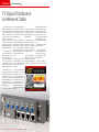
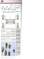
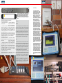
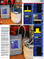
TEST REPORT
TV Via Network Cable
Macab
Catline
TVB-02
96 TELE-audiovision International — The World‘s Largest Digital TV Trade Magazine — 01-02/2014 — www.TELE-audiovision.com
•Distributes analog and digital TV signals using a
standard network cable
•Perfect if only CAT-5/CAT-6 cable was installed
instead of coax cable
•Very easy installation; perfect for beginners
•Existing network cable can now do double duty: for
data and also for regular TV
www.TELE-audiovision.com — 01-02/2014 — TELE-audiovision International — 全球发行量最大的数字电视杂志
97
TEST REPORT
TV Via Network Cable
TV Signal Distribution
via Network Cable
No, this test report is not
about IPTV. Rather it‘s about
the distribution of HF signals
in the 47 to 862 MHz range
through a network cable.
This kind of cable was not
meant to be used for this
purpose; it was originally
meant to carry data. For distributing TV channels in the
47 to 862 MHz range, you‘d
normally use coax cable.
But what should you do if
only network cable was installed in a home or office
with no coax cable for TV?
The company Macab came
up with a very clever solution: the Catline TVB-02. You
simply route the TV signal
through the network cable.
Macab makes use of a
unique condition with network technology: 100 MBPS
networks utilize only six of
the eight wires in a network
cable (1000 MBPS networks
are different though; here
all eight wires in the network
cable are used).
So you might think that
you could simply fashion a
cable adapter that would
connect the center conductor of the coax cable to pin 7
and the coax shield to pin 8
of the RJ-45 plug.
But this doesn‘t work since
the cable and the signal have
totally different properties
and impedances. If you were
to use a CAT-5/6 network
cable with an adapter and
connect it to the coaxial outputs, the signal would not be
usable.
Therefore Macab utilizes
three technologies in their
TVB-02 to make it possible
to use a network cable with
HF signals:
• The signal is amplified to
compensate for the higher
attenuation. This provides
an overall amplification of
the HF signal at the input of
the Catline TVB-02. Then,
the signal for each of the
four outputs can be individually amplified again, to account for the various lengths
of cable.
• There‘s the ability to
compensate for skew in order to obtain the best possible results across the 47 to
862 MHz spectrum.
• The conversion from network cable to coax cable is
accomplished through an
adapter, the TVB-01, that includes a balun on the antenna connector which adapts
the signal (see notes).
The Catline TVB-02 is essentially a cross between
a standard network switch
and an HF signal amplifier. It
is shipped in a see-through
blister package that contains
the TVB-02, power supply,
four special RJ-45 terminations and four screws to
mount the TVB-02 on the
wall. A detailed user manual
is available online for download from the Macab website:
www.macab.tv/en/catline/
products/download.
The principle behind this
and the installation is quite
easy and can even be handled by beginners - without
the manual no less.
You merely connect the
CATV cable to the HF input
01-02/2014
Macab Catline TVB-02
Clever solution to use network cables to
distribute TV signals
www.TELE-audiovision.com/14/01/macab
98 TELE-audiovision International — The World‘s Largest Digital TV Trade Magazine — 01-02/2014 — www.TELE-audiovision.com
1
2
on the TVB-02 and then connect up to four network cables that go to the different
rooms to the four RJ-45 outputs. At the other end is your
typical RJ-45 port.
Here you plug in the special TVB-01 cable that has an
RJ-45 plug on one end and a
normal HF connector for the
antenna input on the other
end. Inside this normal HF
plug is a built-in balun (see
notes) that compensates
for the difference in impedances between the two cable
types.
This TVB-01 cable is offered as an accessory. Depending on your requirements, you would need from
one to four of these cables.
The supplied RJ-45 terminations would be plugged into
any of the unused Catline
TVB-02 RJ-45 outputs.
And that‘s it! You can start
watching TV right away without having to install any new
coaxial cable. And yes, it is
really that simple. The Catline TVB-02 was connected
to the test center‘s main
control cabinet and sure
enough analog CATV, DVBT and even DVB-C could be
transported easily through
the existing network cable.
The installed cable here in
the test center has lengths
of roughly 20-30 meters (65-
3
100 TELE-audiovision International — The World‘s Largest Digital TV Trade Magazine — 01-02/2014 — www.TELE-audiovision.com
1. Block diagram of the Catline TVB-02. The input signal
is amplified and goes through
an
adjustable
attenuation.
After the second stage amplification, there is the adjustable
equalization to make sure that
the RF signal has flatness over
the desired frequency range
rather than being tilted. For
easier signal amplification and
equalization adjustment, a test
point is provided, which has a
-20dB signal loss relative to the
input signal. After an additional
amplification stage the signal
is divided into the four outputs,
where it passes a fourth amplification stage and another individually adjustable attenuation
at the RJ-45 balun output port.
2. This picture shows the schematics to mix the network
signal with the TV signal. For
networks up to 100MBPS only
four of the eight conductors are
used, so Macab decided to use
conductors 7 and 8 (normally
brown/white and brown) for the
TV signal.
3. You don’t have to worry
about making your own special
custom cables, though. Just
use a RJ45 splitter. This will
allow you to connect two network cables and attach them
joined to a single cable. All
pins are connected with each
other among the three involved cables, however this does
not matter at all, as long as you
don’t use any gigabit switch
within your network. The good
news: all different RJ45 splitters I tried have always the
same configuration, so you can
just buy any RJ45 splitter and it
will work.
Installation
4. You can order suitable front plates from Macab to properly mount the Catline TVB-02 in a rack. Instead of just
placing it inside the rack, as I did, this will look much
tidier. Again, Macab was thinking ahead and the rack
front plate allows to fit up to two Catline TVB-02, so that
you can inject the signal into eight separate networking
cables.
4
98 feet), yet the attenuation
was easily compensated for
in the TVB-02 through its
built-in amplifier.
In order to check out the
power of this system a little more closely, additional
tests were performed using
an analyzer, signal generator
and two rolls of cable. One of
them held 100 meters (328
feet) of coax cable (Class A)
while the other held 100 meters (328 feet) of CAT-6 network cable. The results can
be seen in the pictures and
description.
The TVB-02 is an innovative idea that solves a specific problem: how do you
distribute TV signals in the
47 to 862 MHz range without
coax cable? The answer is
very simple: you use CAT-5
or CAT-6 network cable instead. The unit functions as
expected and is quickly and
easily set up.
This gives a simple and inexpensive solution for those
that need to distribute TV
signals in buildings through
network cables instead of
coax cables. The tests in our
offices demonstrated the
overall capabilities of this
system. The ability to suddenly have TV signals available at a network interface
port is an added value.
Up until now, TV and radio channels were streamed
from the Internet and this
annoyed IT administrators
to no end. Now they can provide DVB-T or DVB-C TV and
radio channels without there
being a negative influence
on network traffic like that
which occurs with Internet
streaming.
Macab, with it‘s TVB-02,
has hit a home run!
Notes
Balun
To put it simply, a balun is like an electrical converter
that serves to connect a cable that carries symmetrical
signals to another cable that will carry non-symmetrical
signals. With symmetrical signals you have a positive and
a negative signal, for example, +5V and -5V, while a nonsymmetrical signal works with ground and carries +5V or
0V. The name „balun“ comes from the words ‚balanced‘
and ‚unbalanced‘ where ‚balanced‘ refers to a symmetrical
signal and ‚unbalanced‘ to a non-symmetrical signal.
Tilt
With the TILT control you can set the skew on the TVB02. This is necessary because the attenuation through a
cable varies with the frequency. The higher the frequency,
the higher the attenuation. This makes it necessary to
vary the amplification of the signal in the 47-862 MHz range to prevent over-amplification of the lower frequencies
and under-amplification of the higher frequencies.
Good amplifiers like the amplifier in the Catline TVB-02
permit not only the appropriate amplification but also the
proper skew adjustment as well. In order to correctly set
up an amplifier like this, you would need a signal analy-
5. Close-up view of the Catline
TVB-02. Setup is simple – you just
plug it in, attach the RF cable with
CATV, DVB-C, DVB-T/T2, etc. Attach
the network cable on one of the
four RJ-45 connectors and that’s it.
Make sure to fit the special RJ-45
terminators in the vacant slots.
6. The solution looks very tidy and it
does not matter which cable (network
or TV) is inserted in which port of the
RJ45 splitter. It just works.
7. Does it work? Yes it does! The
meter shows the whole spectrum
and all channels can be received.
Readers paying attention will notice
that I have not perfectly equalized
the tilt: transponders decrease their
levels slightly as the frequency goes
up. Fortunately the Catline TVB-02
provides a TILT knob to adjust this.
8. To prove that the TV signal can
really be used, I tuned into several
analogue CATV channels and DVB-C
transponders. Too little or too much
amplification will both result in a not
so good signal. Also, equalization
with the TILT knob makes much
difference. Having the separate TEST
connector is a blessing: it provides
the signal with -20dB attenuation. This
makes it possible to setup the signal
while you are actually working at the
Catline TVB-02. Hook up the meter
and tune the amplification and TILT
for perfect results. A clever idea by
Macab as otherwise you would have to
constantly run back and forth between
the Catline TVB-02 and the network
socket.
9. Satisfied with my quick test I wanted
to put the Catline TVB-02 to use in a
bigger networking environment, so I
set it up in one of the network racks
in the office. Again, as long as you
can provide the original TV signal in
a coaxial cable, setting up the Catline
TVB-02 is a quick job. Just plug in
the network cables and off you go.
This time I just unplugged the cables
from the switch and into the Catline
TVB-02. The network socket provides
now a TV signal instead of the network
signal.
6
7
zer that can provide a so-called barscan measurement. In
5
this measurement the frequencies are selected and the
respective signal level/performance are displayed as a
8
9
bar graph. Naturally, each channel is displayed in the bar
graph in increasing frequency. A line connects the measured values that would ideally be perfectly horizontal.
102 TELE-audiovision International — The World‘s Largest Digital TV Trade Magazine — 01-02/2014 — www.TELE-audiovision.com
www.TELE-audiovision.com — 01-02/2014 — TELE-audiovision International — 全球发行量最大的数字电视杂志
103
12
14
13
15
10
Testing
16
11
10. Time for to put the Catline TVB-02 under a stress test.
In order to take amplification systems to the limit we use
a cable reel with 100 m of class A coaxial cable. This will
attenuate the signal considerably and allows to test for
example HF amplifiers. It would be quite unusual for a
home or business building to require such a long cable,
but we do like to be on the safe side. We started by testing
a DVB-T2 signal without any amplification. The signal
power was -30dBm at the source, but at the end of our
100m long cable no suitable signal could be found.
11. Hence we attached a simple amplifier to increase the
signal prior to feeding it into the cable reel. This time we
could get the signal at the other end of the cable.
12. The spectrum shows the DVB-T2 transponder at
754MHz with -39.8dBm. This alone is not sufficient to
evaluate the signal quality.
13. The measurements, however, indicate that there is a
lock and the LBER value (Bit Error Ratio after the error
correction) of under 1.0E-8 is pretty good. It means that
you will get less than one erroneous bit in every ten
million bits. The CBER (BER before error correction)
however, is just acceptable at 1.1E-04, it could definitely
be better. The signal power is -30.8dBm, so after the
amplification and the natural attenuation due to the cable
itself we are just 0.8dBm worse than without the 100m
long cable.
14. The constellation diagram of the DVB-T2 signal shows
a near to perfect pattern. Notice that the tilting of the
DVB-T2 constellation is done at the DVB-T2 modulator and
has nothing to do with the tilting obtained by a Barscan.
This is done because at this high modulation schemes a
tilted constellation is more robust and efficient than the
non-tilted modulations of QSPK, QAM or COFDM.
15. Nothing beats the visualisation of the TV live image to
really make sure that the signal is received in full quality.
No problems here.
16. Just to make sure we repeated the test, but this time
with a DVB-C signal. This is a less problematic signal. The
spectrum looks all right.
17. After 100m the signal has a power of -37.9 dBM. Notice
the PRE-BER and POST-BER: absolute dream values.
As a side note: it pays off using quality class “A” cable.
The golden rule is: never try to save money by using low
quality cable to save a bit of money – you will later on
spend much more to compensate for that.
18. Perfect constellation diagram of the DVB-C signal.
This concludes that we can indeed distribute the HF
signal over a 100m long coaxial cable, provided that we
use an amplifier.
104 TELE-audiovision International — The World‘s Largest Digital TV Trade Magazine — 01-02/2014 — www.TELE-audiovision.com
17
18
www.TELE-audiovision.com — 01-02/2014 — TELE-audiovision International — 全球发行量最大的数字电视杂志
105
Testing
19. The question is: can you distribute the
same signal over network cable of CAT-5
or CAT-6 quality? Let’s find out! This time
I used our network cable reel, which holds
100m of CAT-6 cable.
20. The spectrum shows the DVB-T2
transponder. Interestingly, the 100m CAT-6
cable reel was able to capture a nearby
LTE transponder, due to the fact that it has
much less cable isolation than a coaxial
cable. However, this did not influence the
test, as this transponder operates at about
810 MHz. Still, this should remind you that
network cable is much less immune to
these situations than regular coaxial cable.
21. The measurement screen shows that
there is more attenuation using the network
cable and I only achieved an LBER value
of 6.2E-05. This however, is perfectly
acceptable for a DVB-T2 signal and the
signal source was not particularly strong to
begin with – as already mentioned I worked
with a DVB-T2 signal with signal power of
-30 dBm at the output of the source.
22. After fine-tuning the equalisation with
the TILT knob on the TVB-02 the results
improved. The LBER is now <1.0E-8, which
means that we actually got a better result
than with the coaxial cable and a simple
amplifier. And no, there is no magic going
on. Despite having a better LBER value
the constellation it is not as clean as with
the coaxial cable distribution. While there
are no modulation errors, one can clearly
see that the “clouds” are not as close
together than before, indicating that the
signal has suffered from being squeezed
into the network cable. Conclusion: you
can be sure to have great results with the
Catline TVB-02 and you have learned that
you should not only use quality cable, but
quality amplifiers, too.
23. And again: here is the proof. Perfect
picture from a DVB-T2 transponder
distributed over in a 100m long network
cable. Amazing!
24. Next I tested transporting a DVB-C
transponder over the 100m long network
cable using the Catline TVB-02. No surprise
at this point, as the spectrum clearly shows
the transponder at the end of the TVB-01
cable attached to the 100m cable reel.
25. Always a concern: having a good
POST-BER. In this case, we have under
1.0E-9, which is the best possible result.
But look closely: even the PRE-BER has
a value of <1.0E-9. This actually provides
a better result than the coaxial cable with
the simple amplifier we used. This proves
that Macab is using a really good amplifier
within the Catline TVB-02.
26. And the constellation diagram shows a
perfect point cloud as if it came from a text
book. These results are incredible. Never
forget that this HF TV signal just went
through 100m of plain CAT-6 cable.
20
22
21
23
19
24
25
26
106 TELE-audiovision International — The World‘s Largest Digital TV Trade Magazine — 01-02/2014 — www.TELE-audiovision.com
www.TELE-audiovision.com — 01-02/2014 — TELE-audiovision International — 全球发行量最大的数字电视杂志
107
27
28
29
30
Testing
27. What about joining network signals to the TV signal? I just fitted
two RJ45 splitters at both ends of the 100m network cable reel
and on the input side I connected the Rj-45 cable from the Catline
TVB-02 carrying the TV signal and the network cable coming
from the router. On the other end of the cable reel I attached a
regular network cable which I connected with the RJ-45 input
connector of the Deviser S7000 meter. Also, I connected the special
TVB-01 cable on the other port of the RJ45 splitter. The aerial
connector with the integrated balun was then connected with the
RF connector of the Deviser S7000. As a side note: having such a
meter is great, since you can simultaneously measure TV signals
and verify network, as well.
28. The constellation diagram reveals that there is indeed a slight
modification of the signal quality when networking signals are
carried on the same cable. However, after 100m the constellation is
still pretty good. There was a drop in BER but again, this I could be
partially recover by fine tuning the amplification and tilting at the
TVB-02.
29. After fine-tuning for best results PRE-BER decreased slightly
when the network signal is present in the cable, but most
importantly the POST-BER is perfect and that’s what the error
algorithm is there for, anyway.
30. Time to verify if the network signal is working, too. The Deviser
S7000 allows to ping other networking appliances and I simply
pinged the router. No surprise: all five packets reached the router
without delay or problems and hence 5 responses came back. 0%
packet loss means that indeed one can just add the TV signal to
pin 7 and pin 8 of existing network cables and transport it along.
Please bear in mind that this will not work with 1000MBPS (“Gigabit
LAN”), as in such case all 8 conductors of the network cable are
being used. Also, I tried to see if the TV signal would survive a
network switch. The results were not clear. At some tests I could
indeed pass the signal from the Catline TVB-02 over a network
cable into a switch and then from the switch to the receiver using a
second network cable. However, this did not work always. I believe
that this depends on all other devices connected to the switch: if
one has a gigabit network card, then chances are that it will not
work.
31. Transporting analogue CATV channels is of course possible,
as well. The picture shows the result of the signal received when
amplification and equalisations are not properly setup.
32. After an increase in amplification and increasing the tilt
slightly the result improved clearly. Remember, that this signal just
travelled through 100m of network cable.
31
32
108 TELE-audiovision International — The World‘s Largest Digital TV Trade Magazine — 01-02/2014 — www.TELE-audiovision.com
expert
OPINION
Macab Catline TVB-02
TV to RJ-45 amplifier & filter
RECOMMENDED
PRODUCT BY
Vitor Martins
Augusto
Test Center
Portugal
+ ● Easy to setup
● Allows the use of existing CAT-5 or CAT-6 network cable to
distribute analogue and digital TV signals (47-862 MHz)
● Simultaneous data network over the same cable (up to
100MBPS)
● Adjustable amplification to different cable length
– ● No printed manual included
TECHNICAL
DATA
Frequency range 47–862 MHz
Flatness
±0,75 dB
Impedance
Input 75 Ohm
Output 100 Ohm
Gain (47-860MHz)
35 dB (max)
Noise <8 dB
Adjustable attenuation
Input 0–20 dB
Output 0–20 dB
Adjustable slope
0–18 dB
Output level 122 dBµV (DIN45004B)
107 dBµV (42Ch CENELEC)
Return loss (47–862 MHz)
>13 dB
Isolation, port-port
>20 dB
Group delay
<30 ns
Testpoint
–20 dB
Power (via included adapter)
DC 5 V
Power consumption 800 mA
Temperature range
–20 to +60°C
Screening Class B
Connectors
Input – F-female
Outputs – RJ-45 female
Dimensions (LxBxH)
200 x 41 x 38,2 mm
■ TELE-audiovision's Test Bench: During the
test my desk got overloaded with technology.
It is not easy to maintain control of so much
equipment. Fortunately, the Catline TVB-02
is very easy to operate with.
110 TELE-audiovision International — The World‘s Largest Digital TV Trade Magazine — 01-02/2014 — www.TELE-audiovision.com
www.TELE-audiovision.com — 01-02/2014 — TELE-audiovision International — 全球发行量最大的数字电视杂志
111