1
PDrive
Motion Control PMC
User Manual – No. 21 511-EN-11
1 General Information
1
General Information
1.1
Copyright
Copyright 2010 Pilz GmbH & Co. KG
All rights reserved. The implementation of technical changes which improve the performance of
the product is subject to change without prior notification! The product or parts of the content
may be reproduced or transmitted in any form (by printing, photocopying, microfilm or any other
method) or stored, processed, copied or distributed by electronic means without the written
permission of Pilz GmbH & Co. KG.
1.2
Notice
Pilz GmbH & Co. KG reserves the right to make amendments to this document at any time.
The examples given serve only as illustrations. No guarantee is given for their suitability in
particular applications. Although the utmost care has been taken in the production of this
document, no liability can be accepted for any mistakes that it may contain. We welcome any
suggestions for the improvement of our products, or documentation.
We reserve the right to make technical changes, which lead to the improvement of the product!
1.3
Previously published editions
Version
12/2001
V1-16-07-2002
V2-20-11-2002
V3-10-06-2003
V4-11-05-2004
V5-24-02-2005
V6-23-08-2005
V7-16-11-2005
V8-03-05-2006
V9-12-10-2007
V10-18-01-2008
Page 2
Notes
Initial version:
Revised version:
Revised version:
Revised version:
Revised version:
Revised version:
Revised version:
Revision
Revised version:
Revised version:
Revised version:
valid from software version version 2.01
valid from software version 2.03
valid from software version 2.04
valid from software version 2.05
valid from software version 2.06
valid from software version 2.07
valid from software version 2.08
valid from software version 3.0
valid from software version 3.1
valid from software version 3.2
User Manual for Setup Software PDrive
2 Table of contents
2
Table of contents
1
General Information...........................................................................................2
1.1
1.2
1.3
Copyright...........................................................................................................................2
Notice................................................................................................................................2
Previously published editions............................................................................................2
2
Table of contents...............................................................................................3
3
Symbols...............................................................................................................4
4
Safety Guidelines...............................................................................................5
5
About this manual..............................................................................................6
6
Prescribed use (“Use as directed”).................................................................7
7
Installation .........................................................................................................8
7.1
7.2
Hardware requirements.....................................................................................................8
Installation under Microsoft Windows................................................................................8
8
Use.......................................................................................................................9
8.1
8.2
8.3
8.3.1
8.3.2
8.3.3
8.3.4
8.3.5
8.3.6
8.3.7
Notes.................................................................................................................................9
Connection .......................................................................................................................9
Screen layout...................................................................................................................11
Title bar............................................................................................................................12
Menu bar.........................................................................................................................12
Tool bar...........................................................................................................................14
Service bar......................................................................................................................15
Status bar........................................................................................................................16
Select servo amplifier......................................................................................................16
Project window.................................................................................................................17
9
Project window.................................................................................................18
9.1
9.1.1
9.1.2
9.1.3
9.1.4
9.1.5
9.1.6
9.1.7
9.1.8
9.1.9
9.1.10
9.1.11
9.1.12
9.2
9.2.1
9.2.2
9.2.3
9.2.4
9.3
9.4
9.5
9.5.1
9.5.2
9.5.3
9.5.4
9.5.5
Setup...............................................................................................................................18
Basic setup......................................................................................................................18
Units................................................................................................................................19
CAN/Fieldbus..................................................................................................................20
Feedback.........................................................................................................................21
Motor...............................................................................................................................23
Current controller.............................................................................................................25
Speed controller..............................................................................................................26
Position controller............................................................................................................28
Electronic Gearing...........................................................................................................29
Encoder...........................................................................................................................30
Digital I/O.........................................................................................................................31
Analog I/O........................................................................................................................32
Positioning.......................................................................................................................33
Homing............................................................................................................................33
Position Data...................................................................................................................40
Motion task......................................................................................................................42
Position registers.............................................................................................................47
Status..............................................................................................................................48
Monitor.............................................................................................................................48
Screen page „Expansion Card“.......................................................................................49
Expansion card "DA1" ....................................................................................................49
Expansion card "D1"........................................................................................................50
Profibus DP Expansion card............................................................................................51
Expansion card PMCprimo..............................................................................................52
Expansion card PMCprotego S.......................................................................................53
10
Index..................................................................................................................54
User Manual for Setup Software PDrive
Page 3
3 Symbols
3
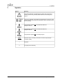
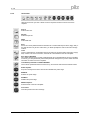
Symbols
Symbol
Meaning
This symbol indicates a possible danger, hazard, risk to life and/ or
health. Ignorance may seriously affect health and cause dangerous
injuries.
This symbol indicates an important hint regarding the correct use of the
product. Ignorance may affect the performance of the machinery and/or
the surrounding.
This parameter applies only to a PMCtendo DD4 and
PMCprimo Drive2
This parameter applies only to a PMCtendo DD5 and
PMCprimo Drive3
This parameter applies only to a PMCprotego D.
[VER]
•
⇒
Page 4
Reference to the according command in the onlne help (example
command „VER“)
Emphasis
see page (cross reference)
User Manual for Setup Software PDrive
4 Safety Guidelines
4
Safety Guidelines
●
When commissioning, you must ensure that neither the controllers nor the amplifiers
present any risk to persons, plant or machinery. Appropriate protection and
precautionary measures must be put in place.
●
●
To avoid personal injury and material damage, only qualified, trained personnel should
work on the devices.
Only specialist staff with extensive knowledge of drive technology and control
engineering should be permitted to program a running drive online. Data stored on data
media is not protected from unintended changes by third parties. Data must be
checked for accuracy before it is loaded on to the hardware.
●
The installation and operating instructions must be read carefully and all safety
regulations observed before installation and initial operation as danger to personnel and
damage to machinery may be caused.
●
Only qualified and well-trained specialists who are familiar with the transportation,
installation, initial operation, maintenance and operation of the units as well as with the
relevant standards may carry out the corresponding works.
●
Technical data and indications (Type tag and documentation) are to be kept absolutely.
User Manual for Setup Software PDrive
Page 5
5 About this manual
5
About this manual
This documentation explains the use of the PDrive.exe setup software for setting
parameters and configuring servo amplifiers of the PMCtendo DD4/5, PMCprimo Drive2/3 and
PMCprotego D series.
The series PMCprimo Drive2/3 differ from the series PMCtendo DD4/5 only in the motion
control functionality.
For this reason the series PMCprimo Drive2/3 is not mentioned furthermore in this
manual. Parameters for the PMCtendo DD4 are concerning the PMCprimo Drive2 too and
parameters for the PMCtendo DD5 the PMCprimo Drive3.
Detailed descriptions of functions and parameters are located in the Object Reference Guide.
The setup software must be installed on a personal computer (PC). The PC is connected
to the servo amplifier by a communication cable. The setup software initiates the communication
between PC and servo amplifier.
With very little effort you can alter parameters and instantly observe the effect on the servo
amplifier, since there is a continuous (online) connection to the amplifier. At the same time,
important actual values are read out from the servo amplifier and displayed on the monitor of the
PC.
Any interface modules (expansion cards), which may be built into the servo amplifier, are
automatically recognized and the additional parameters required for position control or motionblock definition are made available.
You can save sets of data on data media (archiving), and load them again. You can also
print out the data sets.
We provide you with default sets of motor-specific data for all the reasonable combinations of
servo amplifier and motor. In most applications you will be able to commission your drive
without any problems, just by using these default values.
Knowledge of the Microsoft Windows operating system and the use of a personal
computer is assumed.
You must follow the safety, installation and commissioning instructions in the
installation manual for the servo amplifier that is used.
We provide training and familiarization courses on request.
Page 6
User Manual for Setup Software PDrive
6 Prescribed use (“Use as directed”)
6
Prescribed use (“Use as directed”)
The setup software PDrive is intended to be used for altering or storing the operational
parameters for the servo amplifiers of the PMCtendo DD4/5, PMCprimo Drive2/3 and
PMCprotego D series. The servo amplifier that is connected is commissioned with the aid of the
software - whereby the drive can be directly controlled by the setup and service functions.
The characteristic nature of a PC means that these functions are not functionally safe
without further measures. A PC-program might be unexpectedly disturbed or stopped, so
that in the event of a malfunction any movements that have already been initiated cannot
be stopped from the PC.
The manufacturer of the machine must carry out a hazard analysis for the machine, and
is responsible for the functional, mechanical and personnel safety aspects of the
machine. This applies especially to the initiation of movements with the aid of functions
in the commissioning software.
Only personnel who have extensive knowledge in the fields of drive technology and
control technology are permitted to carry out online parameter setting of a drive that is
running.
Sets of data that are stored on data media are not safe from undesirable alteration by
third parties. So after you have loaded a set of data, you must check all the parameters
before enabling the servo amplifier.
The servo amplifiers are components that are built into electrical equipment or machines,
and can only be operated as integral components of such equipment.
The BTB/RTO contact must be wired into the safety loop of the system. The safety loop,
and the Stop and Emergency Stop functions must fulfil the requirements of EN 60204,
EN 292 and VDI 2853.
User Manual for Setup Software PDrive
Page 7
7 Installation
7
Installation
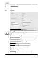
7.1
Hardware requirements
Minimum specification for the PC:
7.2
Operating system
Windows 2000, XP, Vista or 7
Hardware
Minimum requirements of operating system
Interface
one free serial interface
Ethernet interface (optional)
Installation under Microsoft Windows
The PC interface (X6, RS232) of the servo amplifier is connected to the serial interface of the
PC.
You can order the necessary programming cable from us or make one up yourself. The pin
assignment can be found in the installation manual of the servo amplifiers.
Start your PC and insert the Motion Control Tools-CD into the CD-ROM drive. The installation
software will start automatically. Otherwise start MInstall.exe on the CD-ROM.
Click on „Install Motion Control Tools“ and follow the instructions.
Page 8
User Manual for Setup Software PDrive
8 Use
8
Use
8.1
Notes
The setup software is basically used in the same way as other Windows programs. Use a
decimal point as the decimal symbol, do not use a comma.
Please note that, after an alteration in a parameter on a screen page, you must first press
„Return“ or select an other parameter on the page, so that the parameter is transferred to
the RAM of the servo amplifier.
If a reset of the servo amplifier is necessary to activate a function, this will be recognized by the
setup software, which will make a reset after a software confirmation request.
The currently valid data set must be saved in the EEPROM of the servo amplifier, in order to be
permanently stored. So execute the Save Data to EEPROM function on the service bar before
you switch off the servo amplifier or quit processing the data set.
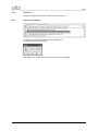
8.2
Connection
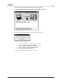
Connect the interface cable to a serial interface on your PC and to the serial interface of the
servo amplifier.
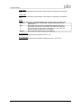
Start PDrive.exe and click to the button:
PDrive is trying to read data from the servo amplifier.
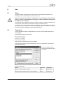
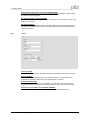
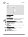
If you have never started a communication before, you have to configure the communication
parameters first (PTerm):
Choose a connection, set the
connection parameters and click
to „Connect“.
Connection parameter:
Device
Baud rate
Handshake
PMCtendo DD4 / PMCprimo Drive2
9600
XON/XOFF
PMCtendo DD5 / PMCprimo Drive3 / PMCprotego D
38400
XON/XOFF
User Manual for Setup Software PDrive
Page 9
8 Use
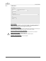
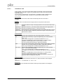
PDrive is now reading the actual parameters of the servo amplifier.
A previously opened data set in PDrive will be overwritten with the new data.
If there is no communication possible, you will receive this message:
In this case check the following:
1.
Is the servo amplifier's 24V supply voltage connected?
2.
3.
4.
Has the correct PC interface been selected?
Has the correct servo amplifier interface been selected?
Has an incorrect connection cable been used?
5.
Has the correct baud rate been set?
Find the error, rectify it and then restart the connection.
Page 10
User Manual for Setup Software PDrive
8 Use
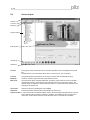
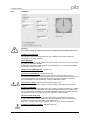
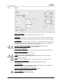
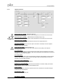
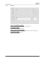
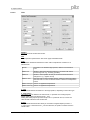
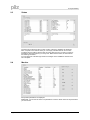
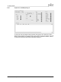
8.3
Screen layout
Title bar
Tool bar
Menu bar
Project window
Main window
Service bar
Status bar
Title bar
The program name and the name of the currently opened document are displayed in the title
bar.
Furthermore the connection status will be shown ("connected" or "not connected").
Tool bar
The typical Windows-style buttons can be used for a direct start of individual functions.
Menu bar
Access to several program functions using Windows menus.
Main view
The main frame allows changing parameters, monitoring actual values of the servo amplifier
and selecting functions.The lower part of this window shows the communication status, the
operate mode, the expansion cards and the axis status. In a network the servo amplier can be
changed in this window, too.
Service bar
Service functions for operating the servo amplifier.
Status bar
Current information about the data communication is shown here.
Project window In a structure similar to Windows Explorer, links to all screen pages are listed that you need for
setup, optimizing and monitoring of the servo amplifier. The selected screen is shown in the
main frame. The top level of the tree shows the name of the connected servo amplifier.
User Manual for Setup Software PDrive
Page 11
8 Use
8.3.1
Title bar
The program name and the name of the currently opened document are displayed in the title
bar.
Furthermore the connection status will be shown ("connected" or "not connected").
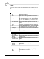
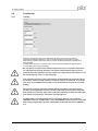
8.3.2
Menu bar
File
New
Creates a new parameter file.
Open...
Opens a parameter file: A parameter data set is read from the
data medium (hard drive, floppy disk). If there is an active
connection, the data set is downloaded to the servo amplifier.
Save parameters
Saves the current parameter data set to a data medium (hard
disk, diskette) while keeping the file name, if the data set already
has a name. If the data set has not yet got a name, you will be
prompted to enter a name and storage location.
Save parameters as...
Saves the current parameter data set to a data medium (hard
disk, diskette). You will be prompted to enter a name and storage
location.
Export as FB for
SoftPLC
Exports the actual parameters into a EXP file. This file can be
imported in the windows program CoDeSys for a Software-PLC.
Print...
The current data set will be printed out. You can choose whether
the print data are sent to the system printer or saved to a file.
Print preview /
Print setup...
Use these functions in the same way as for any other Windows
software.
Send...
Sends the actual data file via E-mail.
Exit
Terminates the program.
Communication
Connect / Disconnect
PC ↔ amplifier
Connect or disconnect PDrive and servo amplifier.
Save parameters to
EEPROM
Saves the current parameter data set permanent in the EEPROM
of the servo amplifier.
Load default
parameters to RAM /
EEPROM
Reset all parameters and load the default parameters to RAM /
EEPROM.
View
Toolbar
Status bar
Service bar
Switch to show/hide the toolbar (above) or the service bar and
status bar (below).
Programs
PTerm
PScope
PEdit
PMotion
primoFTP
Page 12
Starts the tools PTerm (terminal program) ,PScope (scope
function), PEdit (text editor), PMotion (motion generator) or
primoFTP (PMCprimo FTP program).
User Manual for Setup Software PDrive
8 Use
Service
STOP amplifier
Stops the current service function.
ENABLE amplifier
Enables the servo amplifier by software.
DISABLE amplifier
Disables the servo amplifier by software.
RESET amplifier
Software reset of servo amplifier.
CLRFAULT
Clears the current errors and warnings.
Tools
Options
User Manual for Setup Software PDrive
Settings for using the program.
- Show tooltips.
- Default values for PMCprimo Drive.
Page 13
8 Use
8.3.3
Tool bar
All symbols of the toolbar and their meaning:
Standard Windows:
New – open – save
Search – print – send
Connect / Disconnect PC <--> amplifier:
Reads actual parameters from the amplifier. Clicking again diconnects the communication.
Save parameters to EEPROM:
Saves the current parameter data set permanent in the EEPROM of the servo amplifier.
Load default parameters to RAM / EEPROM:
Reset all parameters and load the default parameters to RAM / EEPROM.
PTerm:
Starts PTerm.exe.
PScope:
Starts PScope.exe.
PEdit:
Starts PEdit.exe.
PMotion:
Starts PMotion.exe.
PrimoFTP:
Start primoFTP.exe.
STOP amplifier:
Stopps the current service function and disables power stage.
ENABLE:
Enables power stage.
DISABLE:
Disables power stage.
RESET amplifier:
Software reset of servo amplifier.
Clear Fault:
Clears the current errors and warnings.
Help topics:
Starts online help for PDrive.
Info:
Displays program information, version number and copyright of PDrive.
Current device:
In offline mode, selection as to whether a DD4, DD5 or PMCprotego D parameter file is to be
created. In online mode, displays whether there is a connection to DD4, DD5 or PMCprotego D.
Page 14
User Manual for Setup Software PDrive
8 Use
8.3.4
Service bar
With the service bar you have a direct access to important service functions of the servo
amplifier.
PTerm:
Starts PTerm.exe.
PScope:
Starts PScope.exe.
PEdit:
Starts PEdit.exe.
Save:
Saves the current parameter/motion task data set to a data medium (hard drive, floppy disk). If
the data set does not yet have a file name, you will be prompted to enter a name and storage
location.
Load:
Opens a parameter file: A parameter data set is read from the data medium (hard drive, floppy
disk). If there is an active connection, the data set is downloaded to the servo amplifier.
Save data in EEPROM:
Non-volatile storage of the currently valid parameter set in the EEPROM of the servo amplifier.
In this way you can permanently save all the parameter changes that you have made since the
last switch-on/reset of the servo amplifier.
Load default parameters to RAM / EEPROM:
Cancel all the parameters that have been set up, and load the manufacturer’s default values.
STOP amplifier:
Stop the currently active service function and disables the power stage.
ENABLE:
Enables the power stage.
DISABLE:
Disables the power stage.
RESET amplifier:
Software-reset of the servo amplifier.
Clear Fault:
Clear the present errors and warnings.
User Manual for Setup Software PDrive
Page 15
8 Use
8.3.5
Status bar
Current information about the data communication is shown here.
8.3.6
Select servo amplifier
In a network you can change the actual servo amplifier here.
The following message box appears:
After clicking „Yes“ PDrive reads the data of the chosen servo amplifier.
Page 16
User Manual for Setup Software PDrive
8 Use
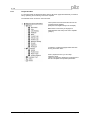
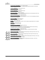
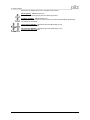
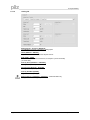
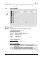
8.3.7
Project window
In a structure similar to Windows Explorer, links to all screen pages are listed that you need for
setup, optimizing and monitoring of the servo amplifier.
The selected screen is shown in the main frame.
The top level of the tree shows the name of the
connected servo amplifier
(PMCprimo Drive2[MOTOR3] in the example).
Below there is a summary of all pages for
parametrization and setup of the servo amplifier
(„Setup“).
„Positioning“ combines all pages which deal with
moving and motion tasks .
Under „Expansion Card“ you can setup
expansion cards.
„Status“ and „Monitor“ display the current status of
the servo amplifier and important parameters.
User Manual for Setup Software PDrive
Page 17
9 Project window
9
Project window
9.1
Setup
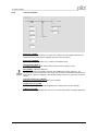
9.1.1
Basic setup
Regeneration resistor [PBALRES]
Internal
The internal regeneration resistor is used.
External
An external regeneration resistor, connected to the terminals +Rbext and -RB , is
used.
Ohm - PMCtendo DD5 and PMCprotego D only
Sets the value of the regeneration resistor in unit Ohm.
Max. Regeneration Power [PBALMAX]
Set the maximum Regen Power.
Max. Mains Voltage [VBUSBAL]
This parameter is used to adjust the regeneration and switch-off levels of the servo amplifiers to
suit the mains power supply voltage or the system conditions for multi-axis systems with
parallel-connected DC-link circuits.
Response to Loss of Input Phase [PMODE]
Handles the message „Phase missing“.
Hardware [HVER]
Display the version and revision level of the servo amplifier hardware.
Firmware [VER]
Display the version and revision level of the servo amplifier firmware.
Name [ALIAS]
Here you can assign a name (8 chars max.) to the servo amplifier.
Serial Number [SERIALNO]
Display the serial number of the servo amplifier.
Run Time [TRUN]
Display the operational time of the servo amplifier, saved at 8 min. intervals.
Page 18
User Manual for Setup Software PDrive
9 Project window
Ambient temperature switch off threshold [MAXTEMPE]
Definition of the threshold for the maximum permitted ambient temperature. If this value is
exceeded, an error is triggered.
Set Software-Enable on Bootup [AENA]
Definition of the status of the software-enable on switching on the instrument, or after using
“Reset“ to clear errors.
Quick-Boot [BOOT]
This can be used to change the behaviour of the amplifier during the initialisation phase. If
Quick-Boot is activated, the internal servo amplifier settings will only be recompiled when
changes are made.
9.1.2
Units
Position [PUNIT]
Definition of the global unit for all position-dependent parameters of the position controller.
Velocity [VUNIT]
Definition of the global dimensional unit for speed and velocity. This unit applies to all
speed/velocity dependent parameters of the speed/position controllers.
Acceleration [ACCUNIT]
Definition of the dimensional unit for acceleration. This unit is used for the ramps of the
trajectory generator as well as for the braking/acceleration ramps of the speed controller.
Resolution counts / Motor Revs [PGEARI] [PGEARO]
You can use the entry fields in this equation to determine the transmission ratio.
User Manual for Setup Software PDrive
Page 19
9 Project window
9.1.3
CAN/Fieldbus
Address [ADDR]
The entry is the station address (1...63) of the servo amplifier. This number is required by the
fieldbus and for the parameter setting of the servo amplifier in multi-axis systems for an
unambiguous identification of the servo amplifier within the system.
External Watchdog [EXTWD]
Definition of the monitoring (watchdog) time for fieldbus/slot communication. This monitoring is
only active when the value is greater than 0 and the output stage is enabled.
Source for fieldbus synchronization [SYNCSRC]
Defines the synchronisation source, if the control loop is synchronised via an interface.
FPGA functionality [FPGA] – PMCtendo DD4 only
Defines the FPGA program that is to be loaded in the initialisation phase.
Baud Rate CAN open [CBAUD]
The entry is the transmission rate of the servo amplifier.
Page 20
User Manual for Setup Software PDrive
9 Project window
9.1.4
Feedback
Warning !
An incorrect setting can cause the motor to run away, even with a speed setpoint n=0 !!
Feedback Type [FBTYPE]
The FBTYPE command is used to select the type of feedback device that is used for the
commutation and velocity controller.
Offset [MPHASE]
Compensates for a mechanical position error of the resolver/encoder in the motor. Change this
only while the amplifier is disabled.
If an encoder with EnDat or Hiperface® is used as a feedback unit, the offset is automatically
transmitted to the servo amplifier.
Number of Poles [MRESPOLES] – resolver only
Standard resolvers have 2 poles.
Encoder Lines [ENCLINES] – Hiperface/EnDat only
ENCLINES sets the resolution (number of lines) of the encoder input channel using an
ENCODER as feedback unit. In case of Rotary Motors it is the number of lines per revolution, in
case of linear Motors it is the number of lines per pole pitch. With an ENDAT or Hiperface
Encoder ENCLINES is read automatically during the initialization process.
Count Direction [DIR] – PMCtendo DD5 and PMCprotego D only
Defines the direction of rotation of the motor shaft in relation to the polarity of the set value.
Bandwidth [MRESBW]
With a wide bandwidth, the drive will respond more rapidly to control-loop deviations => smaller
following error. A very wide bandwidth only makes sense with low moments of inertia, low KP,
and very high values of acceleration. A narrower bandwidth produces a filter effect. The speed
and positional control are smoother (the encoder emulation is quieter as well).
Observer-Feedforward [VLO]
This parameter applies a dynamic pre-control to the actual-value detection (Luenberger
monitor), particularly for resolver feedback. It reduces the phase-shift in the detection of the
actual value, thus improving the stability of the speed control.
With VLO = 1 the pre-control is set to optimum, with VLO = 0 the monitor is switched off.
Feedback Filer Mode [FLTMODE] – PMCtendo DD4 only
Feedback Filter Mode.
User Manual for Setup Software PDrive
Page 21
9 Project window
Number of multi-turn bits [SSIREVOL] – PMCtendo DD5 and PMCprotego D only
Defines the number of multi-turn bits in an SSI communication.
Number of SSI bits to read [SSIRXD] – PMCtendo DD5 and PMCprotego D only
Establishes the number of SSI bits to read
Resolver Signal [RK]
The RK parameter can be used to correct any amplitude difference that may exist between the
sine and cosine signals from the resolver.
Press the button “Calculate RK” for automatic calculation.
No overvoltage surveillance [DRVCONFIG] (Bit 6)
Monitoring of the maximum voltage of the sine/cosine encoder at X1 is deactivated.
No overflow surveillance [DRVCONFIG] (Bit 7)
Overflow monitoring of a multi-turn encoder is switched off.
Single turn executed as multi turn encoder [DRVCONFIG] (Bit 8)
A single-turn encoder is treated as a multi-turn encoder. The absolute position within a
revolution is taken on power-up. A reference run is not required.
Angle of rotation
Shows the mechanical angle of rotation.
Page 22
User Manual for Setup Software PDrive
9 Project window
9.1.5
Motor
Motor Type [MTYPE]
MTYPE sets the amplifier's control algorithms to different motor types.
I0 [MICONT]
The standstill current is the r.m.s. current value that the motor requires at standstill to produce
the standstill torque (defines the maximum value for the entry of Irms in the current controller).
I0max [MIPEAK]
The peak current (r.m.s. value) should not exceed 4 x the rated current of the motor. The actual
value is also determined by the peak current of the servo amplifier that is used (defines the
maximum value for the entry of Ipeak in the current controller).
El. Therm. Time Constant [MTIME] – PMCtendo DD5 and PMCprotego D only
Motor thermal time constant to calculate MI2T with MICONT.
Maximum Speed [MSPEED]
Maximum permissible speed of the motor. Limits the entry for the parameter SPEED LIMIT.
Number of Poles [MPOLES]
The number of motor poles per turn of the motor.
L [ML] -PMCtendo DD5 and PMCprotego D only
Inductance of the motor (phase-phase). You can take this value from the motor manual.
L [L] – PMCtendo DD4 only
Inductance of the motor (phase-phase). You can take this value from the motor manual.
Stator Wind. Resistance [MRS]
The parameter describes the stator winding resistance phase-phase in Ohm.
Brake [MBRAKE]
If you want to operate a 24V holding brake in the motor directly from the servo amplifier, this
parameter can be used to enable the brake function.
Velocity threshold commutation error [VCOMM]
Defines the velocity threshold for commutation error monitoring.
Motor Unit [MUNIT] – PMCtendo DD4 only
Unit for all speed-dependent motor parameters.
User Manual for Setup Software PDrive
Page 23
9 Project window
Current Advance [MTANGLP] – not for Induction Motor
A current-dependent phase advance, to make use of the reluctance torque for motors with
magnets embedded in the rotor.
Limit Phi [MVANGLF] – not for Induction Motor
Velocity-dependent Lead (Limit Phi).
Start Phi [MVANGLB] – not for Induction Motor
Velocity-dependent Lead (Start Phi).
Rated Speed [MVR] – Induction Motor only
In asynchronous motor mode, the parameter MVR must be set to the rated speed of the motor.
This is the threshold for the start of field attenuation.
Rotor Time Constant [MTR] – Induction Motor only
Defines the rotor time constant under rated load (Tr = Lh/Rr). Lh is die magnetizing inductance
and Rr is the rotor resistance.
Field Level [MIMR]– Induction Motor only
Magnetizing Current (Induction Motor).
KP [GF] – Induction Motor only
Proportional gain (P) of the flux controller. The flux controller is implemented as a PI controller.
TN [GFTN] – Induction Motor only
Reset (I) time of the flux controller.
Field Correct Factor [MCFW] – Induction Motor only
Correction factor for field-weakening.
The correction factor compensates for non-linearity of the motor inductance with reducing
magnetizing current by increasing speed during field-weakening.
Slip Correct Factor [MCTR] – Induction Motor only
Correction factor for the rotor (armature) time constant, increases the torque in the fieldweakening range /stationary range.
Rated Frequency [MFR] – PMCtendo DD5 and PMCprotego D with asynchronous motor only
Rated frequency of the asynchronous motor.
Rated Voltage [MUR] – PMCtendo DD5 and PMCprotego D with asynchronous motor only
Rated voltage of the asynchronous motor.
Initial Voltage Factor [VSTART] – PMCtendo DD5 and PMCprotego D with async. motor only
Initial voltage as a fraction of the rated voltage.
Power Factor [MCOSPHI] – PMCtendo DD5 and PMCprotego D with async. motor only
Power factor of the asynchronous motor.
Page 24
User Manual for Setup Software PDrive
9 Project window
9.1.6
Current controller
Ipeak (pos.) [IPEAK]
Sets the required pulse current (r.m.s. value). The value that can be entered is limited to the
rated peak current of the motor or amplifier (the lower of the two values).
Ipeak (neg.) [IPEAKN]
Sets the intended pulse current (r.m.s. value) for the negative range.
Homing IPeak [ REFIP ]
The REFIP parameter can be used to set the peak current for homing to a stop.
Irms [ICONT] – PMCtendo DD4 only
Sets the rated output current that is required. The adjustment is usually made to I0 , the
standstill current for the motor that is connected. The value that can be entered is limited to the
rated current of the servo amplifier or the standstill current of the motor Io (the lower of the two
values).
Proportional Gain (Kp_i) [MLGQ]
Determines the proportional gain of the current controller.
Integral Time (Tn_i) [KTN]
Determines the integral-action time (integration time constant) of the current controller.
I2t-Warning [I2TLIM]
Sets the level, as a percentage value of the r.m.s. current, above which a message will be sent.
User Manual for Setup Software PDrive
Page 25
9 Project window
9.1.7
Speed controller
Speed Limit (pos.) [VLIM] – PMCtendo DD4 only
Limits the motor speed. The maximum value also depends on the used motor and encoder.
Speed limit (pos.) [VLIMP] – PMCtendo DD5 and PMCprotego D only
Limits the motor speed. The maximum value also depends on the used motor and encoder.
Speed limit (neg.) [VLIMN]
The VLIMN parameter defines the maximum velocity for the negative direction.
Overspeed [VOSPD]
Determines the upper limit for the motor speed. If this limit is exceeded, the servo amplifier
switches into the fault condition.
Count direction [DIR] – PMCtendo DD4 only
Fixes the direction of rotation of the motor shaft, referred to the polarity of the setpoint.
Acc. Ramp [ACC]
Limits the rate of increase of the internal setpoint processing during acceleration to the speed
limit (valid for both directions). A jump or step in the setpoint that is provided will be turned into a
smoother, more favourable transition.
Dec. Ramp [DEC]
Limits the rate of decrease of the internal setpoint processing during braking to the zero speed
(valid for both directions). A jump or step in the setpoint that is provided will be turned into a
smoother, more favourable transition.
Emerg. Dec. Ramp [DECSTOP]
The breaking ramp for emergency breaking.
Disable Dec. Ramp [DECDIS]
When the output stage is disabled (removal of the hardware or software enable), the internal
speed setpoint is set to 0, using the preset DECDIS ramp.
PI-Plus [GVFR]
With the default setting, the speed controller functions as a standard PI-controller with slight
overshoot in the step response.
Prop Gain Kp_v [GV]
Determines the proportional gain.
Int. Time Tn_v [GVTN]
Page 26
User Manual for Setup Software PDrive
9 Project window
Determines the integral-action time / integration time constant.
PID-T2 [GVT2] – PMCtendo DD4 only
Affects the proportional gain (P-gain) at medium frequencies.
Feedback [GVFBT] – PMCtendo DD4 only
If necessary, the time constant for the PT1-filter in the actual speed feedback (tachometer
smoothing) can be altered.
LP-Frequency [ARLPF] – PMCtendo DD5 and PMCprotego D only
Frequency limit low pass filter.
HP-Frequency [ARHPF] – PMCtendo DD5 and PMCprotego D only
Frequency limit high pass filter.
User Manual for Setup Software PDrive
Page 27
9 Project window
9.1.8
Position controller
Feedback [EXTPOS]
The EXTPOS command defines the feedback source for the drive position control loop.
Prop Gain Kp_p [GP]
Determines the proportional gain for the position controller.
Tn [GPTN] – PMCtendo DD4 only
Determines the integral-action time (integration time constant) for the position controller.
Prop Gain Kp_v [GPV]
Determines the proportional gain for the speed section of the controller.
FF-Faktor Speed [GPFFV]
Determines the feed-forward factor for the position controller.
FF-Faktor Current [GPFFT] – PMCtendo DD4 only
Position control loop: feed forward for the current command.
Count Direction [DIR] – PMCtendo DD5 and PMCprotego D only
The DIR variable defines the count direction for feedback information.
Resolution [ENCIN/EGEARO/EGEARI] – PMCtendo DD5 and PMCprotego D only
ENCIN sets the resolution (number of pulses) of the encoder input channel using a digital
encoder as feedback unit.
In case an external feedback system is used the ratio can be set by EGEARI and EGEARO.
The feedback turn are set by EGEARI the motor turn by EGEARO.
Page 28
User Manual for Setup Software PDrive
9 Project window
9.1.9
Electronic Gearing
External Gearing Source [GEARMODE]
The servo amplifier can be controlled through different interfaces and from various sources.
Ratio [GEARO] / [GEARI]
You can use the entry fields in this equation to determine the transmission ratio.
Input Filter [GEARFILT] – PMCtendo DD5 and PMCprotego D only
This command GEARFILT can be used to configure the filter and determine the corresponding
frequency of the electronic gearing filter.
Count Direction [DIR] – PMCtendo DD5 and PMCprotego D only
The DIR variable defines the count direction for feedback information.
Lines per Revolution [ENCIN] – PMCtendo DD4 only
ENCIN sets the resolution (number of pulses) of the encoder input channel using a digital
encoder as feedback unit.
User Manual for Setup Software PDrive
Page 29
9 Project window
9.1.10
Encoder
Encoder-Emulation [ENCMODE]
Selection of the digital encoder channel.
Resolution [ENCOUT]
Determines the number of increments per turn that are output (ROD).
Zero Pulse Offset [ENCZERO]
Determines the position of the zero (marker) pulse when A=B=1. The entry is referred to the
zero-crossing of the feedback unit.
Transmit Timeout SSI [SSITOUT] – PMCtendo DD5 and PMCprotego D only
The command SSIOUT sets the monoflop - timeout of the SSI – transmission.
No. of Bits (Multi-/Single-Turn) [SSIREVOL] – PMCtendo DD5 and PMCprotego D only
Command ‘SSIREVOL’ sets the number of turns (MultiTurn) for SSI – Transmission.
Baud Rate [SSIOUT] – PMCtendo DD4 only
Determines the serial transmission rate. Change this only while the amplifier is disabled.
SSI-Takt [SSIINV] – PMCtendo DD4 only
Determines whether the output level is normal, or inverted. Change this only while the amplifier
is disabled.
SSI Code [SSIGRAY]
Determines whether the output is in binary or GRAY code. Change this only while the amplifier
is disabled.
Number of SSI bits to read [SSIRXD] – PMCtendo DD5 and PMCprotego D only
Establishes the number of SSI bits to read
Input Edge [ENCCAPT] – PMCtendo DD4 only
Determines the triggering edge and thus the quiescent level of the clock line. Change this only
while the amplifier is disabled.
SSI-Mode [SSIMODE] – PMCtendo DD4 only
Determines the encoder type (Single turn or Multi turn).
Page 30
User Manual for Setup Software PDrive
9 Project window
9.1.11
Digital I/O
Input 1 – Input 4 [IN1MODE – IN4MODE]
The command is used to configure the function of the digital inputs.
Var. x [IN1TRIG – IN4TRIG]
Auxiliary trigger variable for the digital inputs.
Output 1 – Output 2 [O1MODE – O2MODE]
You can combine the following standard pre-programmed functions with the digital outputs.
Var. x [O1TRIG – O2TRIG]
Auxiliary variable for the digital outputs.
User Manual for Setup Software PDrive
Page 31
9 Project window
9.1.12
Analog I/O
Analog-Inputs – Function [ANCNFG]
The ANCNFG command configure the analog inputs.
Offset [ANOFF1 - ANOFF2]
Adjust the axis to standstill while the setpoint SW=0V.
Filter [AVZ1 - AVZ2]
You can enter a filter time constant here, for setpoint 1 (clock rate 8 kHz)
(1st order filter).
Velocity Scale [VSCALE1 - VSCALE2]
Scaling of the speed setpoint value.
Current Scale [ISCALE1 - ISCALE2]
Scaling of the torque setpoint value.
Velocity Deadband [ANDB]
Suppresses small input signals.
Analog Output 1+2 [ANOUT1 – ANOUT2] – PMCtendo DD4 only
Configuration of the analog outputs.
Page 32
User Manual for Setup Software PDrive
9 Project window
9.2
Positioning
9.2.1
Homing
Reference traversing (homing) is an absolute task that is used to zero the drive for
subsequent positioning operations. You can choose between various types of homing.
After homing, the drive reports "InPosition" and then enables the position controller in the
servo amplifier.
The limit switch functions: 2, PSTOP and 3, NSTOP must be activated for digital inputs 3
or 4 to achieve full homing functionality.
Be sure that the zero point of the machine (reference point) is in a position that allows
the subsequent positioning operations. The software limit-switches that were set as
parameters may be ineffective. The axis could move to the hardware limit-switch or even
the mechanical stop. There is a risk of damage.
If the reference point (zero point of the machine) is approached with excessive velocity,
(for instance, because of high moments of inertia), it may be overshot and, in the worst
case, move to the hardware limit-switch or even the mechanical stop. There is a risk of
damage.
The position controller cannot be operated without first making a reference traverse
(homing). A homing/reference traverse must be made after the 24 V supply voltage has
been switched on. The start signal must not be removed during homing. The start signal
must remain present until the "InPosition" message appears.
The SW-enable is set automatically when homing starts. Homing is only started in
OPMODE 8. However, the SW-enable is set in all OPMODEs. The drive can be accelerated
by an analog setpoint that is applied, if the START command is executed in OPMODE 1
or 3.
User Manual for Setup Software PDrive
Page 33
9 Project window
9.2.1.1
Homing [NREF]
You can choose which type of reference traverse should be performed.
No
Function
Reference point is...
0
Set Home Reference
immediately
the setpoint position
1
Home Switch and Zero
Pulse
the first feedback zero-mark outside the home
switch
2
Limit Switch and Zero Pulse the first feedback zero-mark outside the limit
switch
3
Home Switch without Zero
Pulse
the edge of the home switch
4
Limit Switch without Zero
Pulse
the edge of the limit switch
5
within one Revolution and
Zero Pulse
the next feedback zero-mark
6
Set Ref.Point immediately
on Position Command
the actual position
7
Move to Mechanical Stop
the first feedback zero-mark outside the mechanical stop.
(Ref. Ipeak) and Zero Pulse Peak current is limited to Homing Ipeak during
the movement. (see screen page "Current
Loop").
8
Move to an absolute SSIPosition
the read position from the SSI input at the
beginning of the homing
9
Move to Mechanical Stop
(Ref. Ipeak) without Zero
Pulse
the actual position, when the drive is at the mechanical
stop and the following error reaches
50% of the max. allowable following error.
Peak current is limited to Homing Ipeak during
the movement. (see screen page "Current
Loop").
Direction of Motion [DREF]
Determines the direction of motion for homing. The setting "distance-dependent" is only
relevant for Homing 5 (within one turn). In this case, the direction is chosen to give the
shortest distance to the zero-mark. This parameter also defines the direction of motion
for a Modulo type of axis.
Homing Speed [VREF]
Speed for the homing operation. The sign is automatically fixed by the selected direction
of motion.
Reference Offset [ROFFS]
With the reference offset you can assign an absolute position value other than 0 to the
reference point. With an offset for the reference position, you are not actually making a
physical change, but the offset is used as a reference value within the position control of
the servo amplifier. Homing to the reference switch does not finish at zero, but at the
preset reference offset value.
The reference offset must be set before homing is started.
Acceleration Ramp [ACCR]
Acceleration ramp for homing operation. This ramp is also valid for jog mode.
Deceleration Ramp [DECR]
Deceleration ramp for the homing operation. This ramp is also valid for jog mode. This
deceleration ramp is only used if the operating mode allows it. For homing to a hardware
limit-switch, the emergency ramp is used.
Page 34
User Manual for Setup Software PDrive
9 Project window
9.2.1.2
Homing type 0
Sets the reference point to the setpoint position (the following error is lost). The load
does not move.
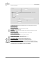
9.2.1.3
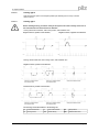
Homing type 1
Before starting homing, check the safety of the system since the load may move even if
the limit-switches are disconnected or defective.
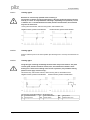
Homing without limit switches, with homing switch, with feedback zero:
Negative traverse, positive count direction,
Negative traverse, negative count direction
Homing with limit switches, with homing switch, with feedback zero
Negative traverse, positive count direction
Positive traverse, positive count direction
The meanings of the abbreviations in the drawings are:
Limit switch NSTOP
Limit switch PSTOP
N
P
R
Homing switch
User Manual for Setup Software PDrive
vref
preset velocity
SP
Start position
NM
feedback zero mark
Page 35
9 Project window
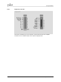
9.2.1.4
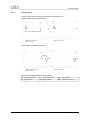
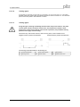
Homing type 2
Homing with limit switches, without homing switch, with feedback zero
Negative traverse, positive count direction
Positive traverse, positive count direction
The meanings of the abbreviations in the drawings are:
Limit switch NSTOP
Limit switch PSTOP
N
P
R
Page 36
Homing switch
vref
preset velocity
SP
Start position
NM
feedback zero mark
User Manual for Setup Software PDrive
9 Project window
9.2.1.5
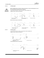
Homing type 3
Before starting homing, check the safety of the system, since the load may move, even if
the limit-switches are disconnected or defective.
Homing with limit switches, with homing switch, without feedback zero
Negative traverse, positive count direction
Positive traverse, positive count direction
9.2.1.6
Homing type 4
Homing with limit switches, without homing switch, without feedback zero
Negative traverse, positive count direction
Positive traverse, positive count direction
User Manual for Setup Software PDrive
Page 37
9 Project window
9.2.1.7
Homing type 5
Behavior for successively repeated starts of Homing 5:
The position controller can only hold the motor in the zero position by passing the zero
mark by ± 1 count. On a repeated start of Homing 5, depending on the position (1 count
in advance of or 1 count behind the zero-mark) and the count direction, the movement
may be a full motor turn!
Homing with limit switches, without homing switch, with feedback zero
Negative traverse, positive count direction
9.2.1.8
Positive traverse, positive count direction
Homing type 6
Sets the reference point to the actual position (the following error is not lost). The load does not
move.
9.2.1.9
Homing type 7
Using this type of homing can damage the mechanical stop on the machine. The peak
current, Ipeak, and the continuous current, Irms, are limited for the duration of the
homing run. A more severe limiting of the current is possible. (see parameter Homing
Ipeak on screen page "Current Loop").
Mechanical stop, without limit switches, without homing switch, with feedback zero.
Negative traverse, positive count direction
Positive traverse, positive count direction
The meanings of the abbreviations in the drawings are:
Limit switch NSTOP
Limit switch PSTOP
N
P
R
Page 38
Homing switch
vref
preset velocity
SP
Start position
NM
feedback zero mark
User Manual for Setup Software PDrive
9 Project window
9.2.1.10
Homing type 8
Prerequisite: an absolute encoder (SSI) is connected to to the encoder input X1 of the servo
amplifier. When the homing starts, the absolute position is read at connector X1. The reference
point is set to this position. The load does not move..
9.2.1.11
Homing type 9
Using this type of homing can damage the mechanical stop on the machine. The peak
current, Ipeak, and the continuous current, Irms, are limited for the duration of the
homing run. A more severe limiting of the current is possible. (see parameter Homing
Ipeak on screen page "Current Loop").
Mechanical stop, without limit switches, without homing switch, without feedback zero
Negative traverse, positive count direction
Positive traverse, positive count direction
The meanings of the abbreviations in the drawings are
Limit switch NSTOP
Limit switch PSTOP
N
P
R
Homing switch
User Manual for Setup Software PDrive
vref
preset velocity
SP
Start position
NM
feedback zero mark
Page 39
9 Project window
9.2.2
Position Data
Axis type [POSCNFG]:
Here you select whether the axis is to be operated as a linear or a rotary axis.
Linear axis
A linear axis is an axis with a limited range of travel. A linear axis moves
within the traversing limits that are given by the software limit-switches, both
absolutely and relatively. A reference point must be set.
Modulo axis
Axis with a limited range of movement. The minimum position is SRND and
the maximum position is ERND-1. If the maximum position ERND-1 is
reached, it automatically switches over to SRND. The absolute target
positions have to be in the defined range. If a motion task is started, which
has a absolute position outside the range, a warning "n08" is displayed
(wrong motion task). Relative moves are calculated in a way, that the target
position always is in the defined range. A positioning in a axis like this, gives
two possibilities of direction to the target position. DREF gives the possibility
to restrict the direction. This axis type also needs a homing move.
Max. Following Error [PEMAX]
The following error is the maximum difference (+/- window) between the position setpoint and
the actual position that is permitted during processing. If the value leaves this window, then the
position controller generates an error message and brakes the drive, using the emergency
ramp.
In-Position window [PEINPOS]
Sets the InPosition window. Determines at which distance from the set position the „InPosition“
message should be reported. The drive moves precisely to the target position.
Modulo Start-Position [SRND]
The SRND parameter is used to define the start of the range of movement for a modulo axis.
Modulo End-Position [ERND]
The ERND parameter is used to define the end of the range of movement for a modulo axis.
V max(pos.) [PVMAX]
This parameter is used to adjust the maximum speed of movement to suit the limits of the
operative machinery.
V max(neg.) [PVMAXN]
The parameter PVMAXN defines the maximum velocity (in the negative direction) that is
permitted for a motion task.
Page 40
User Manual for Setup Software PDrive
9 Project window
a-max [PTMIN]
A drive is always so dimensioned that it can provide more power than the application requires.
This parameter determines the limit for the maximum mechanical acceleration time to v_max,
that must not be exceeded by the drive.
1 Neg.-SW-limit switch – 2.Pos.-SW-limit switch [SWCNFG]
Configuration variables for the position register. SWCNFG is a binary-coded bit-variable, and is
transferred to the ASCII terminal program as a decimal number.
at Position [SWE1 – SWE2]
The variable contains the position value for the position register.
User Manual for Setup Software PDrive
Page 41
9 Project window
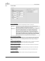
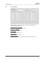
9.2.3
Motion task
9.2.3.1
Overview
For each positioning task, you must define motion tasks. These motion tasks are selected by a
motion task number and stored in the servo amplifier.
Motion task No. Memory
Precondition
Note
1 .. 180
output stage disabled
permanently stored
EEPROM
192 .. 255
RAM
none
volatile storage
When the servo amplifier is switched on, the RAM motion tasks are automatically initialized with
the parameters of the EEPROM motion tasks 1 .. 64.
Motion task No. Memory
Precondition
Note
1 .. 200
output stage disabled
permanently stored
EEPROM
201 .. 300
RAM
none
volatile storage
When the servo amplifier is switched on, the RAM motion tasks are automatically initialized with
the parameters of the EEPROM motion tasks 1 .. 100.
All motion tasks are represented in tabular form. All motion task parameters can be
entered in the table directly. The standard Windows operations are available (Cut, Copy,
Paste, Delete).
The clipboard operations cut, copy and paste are only possible for complete rows so, for
these operations, the appropriate row must be selected. A line can be selected either by clicking
on the row number, or through the keyboard shortcuts <Shift>+<Space>. Double-clicking a line
number in the table opens the screen page for the associated
motion task.
The SW-enable is automatically set when the motion task starts.
The motion task is only started in OPMODE 8. However, the SW-enable is set in all
OPMODEs.
The drive can be accelerated by an analog setpoint that is applied, if the START
command is executed in OPMODE 1 or 3. The motion task is not started if the target
position is beyond the defined SW-limit switches (warning messages n06/n07 and n08).
Page 42
User Manual for Setup Software PDrive
9 Project window
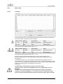
9.2.3.2
Edit
Number
Displays the active motion task number.
Unit
Unit for path and speed entries. See screen page "Units/Mechanical".
Type
This selection determines whether the motion task is interpreted as a relative or an
absolute task.
Absolut
movement to an absolute target position, relative to the reference
point
Relativ soll
relative to last target (setpoint) position (in connection with motion
block changeover: e.g., summing operation)
Relativ ist
relative to actual position at start (in connection with motion block
changeover: e.g., register control)
Relativ In-Pos
when the load is in the InPosition window: relative to last target position
when the load is not in the InPosition window: relative to actual position
at start
Relativ Latch pos contact our applications department
Relativ Latch neg contact our applications department
x_cmd
This parameter defines the distance or the target position, depending on the motion type.
V_cmd_Source
The velocity can be defined in the motion block, or provided as an analog setpoint.
digital: digital setpoint provision through v_cmd.
Analog IN1:analog setpoint provision at input An In 1 (terminals X3/4-5, is used. The
value is read at the start of the motion task.
V cmd
This parameter determines the velocity of movement for digital setpoint provision. If
v_max is set to a value less than v_cmd at a later time, the position controller uses the
smaller value.
User Manual for Setup Software PDrive
Page 43
9 Project window
Page 44
User Manual for Setup Software PDrive
9 Project window
t_acc_total
This parameter determines the acceleration ramp steepness, depending on the selected
units.
t_dec_total
This parameter determines the deceleration ramp steepness, depending on the selected
units.
Ramp
Determines which type of acceleration/braking ramp is used to carry out a motion task.
Trapeze
The drive is given a constant linear acceleration/deceleration to the
target speed.
Sine²
To limit any jolting, the drive is accelerated/decelerated within the
acceleration time along an acceleration ramp without any disruptions.
The resulting speed characteristic corresponds to a sine² curve. The
profile is stored in a table in the servo amplifier.
variable
The acceleration/braking ramps can be adjusted.
Acc. Ramp (T1)
This parameter determines the acceleration time to v_cmd.
Dec. Ramp (T2)
This parameter determines the deceleration (braking) time from v_cmd to zero.
User Manual for Setup Software PDrive
Page 45
9 Project window
9.2.3.3
Next Motion Task
Select whether a new motion task should be started automatically, after the present task
is complete. The „InPosition“ signal is only enabled when the last motion task (no further
task) is processed.
You can use the output function "16, Next-InPos" to generate a signal at a digital output
when each target position within a sequence of motion tasks has been reached.
Next Number
The number of the next task, which starts automatically after the current task is
complete.
Acc/Dec
Select the action to be taken when the target position for the present motion task is
reached.
on v=0
The drive brakes to a stop in the target position. The next motion task is then
started.
beginning at
The drive moves at v_cmd of the present motion task to the target position,
target position and then accelerates through to v_cmd of the next task.
complete at
The changeover to the next task is brought so far forwards, that the v_cmd of
target position the next task is already achieved by the time the target of the present motion
task has been reached.
Start Condition
immediately
The next task is started as soon as the target position is reached.
I/O
The next task is started by a signal at a digital input (one of the terminals
X3/11...14).
This is only meaningful with "Acceleration/Deceleration to v=0".
Condition: the digital input must have the function „15, Start_MT Next“
assigned, and the target position must have been reached.
You can pre-select the logic with the „Start with“ parameter.
Time
The next task is started with a defined delay after the target position has been
reached. You can enter the delay time with the „Delay time“ parameter.
This is only meaningful with "Acceleration/Deceleration to v=0".
I/O or Time
The next task is started by a signal at a digital input (one of the terminals
X3/11...14) or after a defined delay.
This is only meaningful with "Acceleration/Deceleration to v=0".
The trigger is the event that occurs first (the start signal or the end of the delay
time).
Condition: the digital input must have the function “15, Start_MT Next“
assigned, and the target position must have been reached.
You can pre-select the logic with the „Start with“ parameter, and enter the
delay time with the „Delay time“ parameter.
Start by I/O Edge
The logic for the digital input that has the function "15, Start next Motion Task" assigned
to it.
LOW-level: 0 ... 7 V HIGH-level: 12 ...3 0 V / 7 mA
Delay Time
The entry (in ms) for the delay time between reaching the target position and starting the
next task.
Page 46
User Manual for Setup Software PDrive
9 Project window
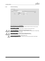
9.2.4
Position registers
Exceeding or falling of up to 16 position values in the motion way can be monitored.
The actual position is visible as well.
Enable Positionsregisters [WPOS]
The fast position registers are enabled by WPOS.
No. active 1 – 16 [WPOSE]
Enable Fast Position Registers 1 ... 16.
check [WPOSX]
Mode of Fast Position Registers 1 ... 16.
Signal, [WPOSP]
Polarity of Fast Position Registers 1 ... 16.
if Position... [P1 - P16]
The variables P1 ... P16 contain the position values for the position thresholds 1 ... 16.
User Manual for Setup Software PDrive
Page 47
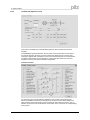
9 Project window
9.3
Status
The actual error status and the run time monitor of the servo amplifier are displayed
here. Compare to the runtime status you can simply calculate when an error occurs.
Top left is the error history with the time (run time) when the error occured. Top right is
information about the frequency for every error. Below these frames, the actual errors
and warnings are listed.
You can find a list of all warnings and error messages in the installation manual of the
servo amplifier.
9.4
Monitor
All important parameters are displayed.
Additionally, you can see the value of 5 parameters. Fill in the ASCII names of the parameters
you want to see.
Page 48
User Manual for Setup Software PDrive
9 Project window
9.5
Screen page „Expansion Card“
The design of screen page "expansion card" depends on the installed expansion card:
9.5.1
Expansion card "DA1"
The expansion card DA1 is available only for PMCtendo DD4 with a special firmware
version.
For getting information please consult our applications department.
CAM 1 / CAM 2 [CAM1 / CAM2]
Position cams for the digital outputs O1 and O2.
Syntax: CAMx number Start offset length
number:
Start offset:
Length:
number of signals in one cycle (max. 30)
Start position 1st CAM
CAM length
Example:
CAM1 5 1000 500
Output O1; 5 CAM; 1st CAM starts at 1000; each CAM 500 units long
Number = 0 deletes the definition
Cycle length [CYCLES]
Defines the whole cam cycle in
CYCLES
2
motor cycles.
Position mode [CYCLEMODE]
0
normal positioning: Rotating direction depends on the actual position.
1
shortest positioning: The cycle length is considered; the axis takes the shortest
way to the position.
2
only positive positioning: The axis moves only in positive direction.
3
only negative positioning: The axis moves only in negative direction.
User Manual for Setup Software PDrive
Page 49
9 Project window
9.5.2
Expansion card "D1"
This screen is available only if an I/O extension card is inserted into the servo amplifier.
The status of the 14 additional inputs and 8 outputs is displayed here.
Page 50
User Manual for Setup Software PDrive
9 Project window
9.5.3
Profibus DP Expansion card
This screen is available only if a PROFIBUS extension card is inserted into the servo
amplifier.
The PROFIBUS-specific parameters, the bus status, and the data words in the transmit
and receive directions (as seen by the bus-master) are displayed on this screen page.
This page is helpful when searching for errors and commissioning the bus communication.
The data for input/output are only transferred, if the threshold monitoring for the servo
amplifier is active in the master’s hardware configuration.
Instrument Control:
On this screen page, the bit states are displayed for the control word (STW) and the
status word (ZSW). The instrument state given by the status word is made visible in the
state machine. The present state is shown in black. All other states are shown in gray. In
addition, the previous state is indicated by accentuation of the number for the corresponding
arrow symbol.
User Manual for Setup Software PDrive
Page 51
9 Project window
9.5.4
Expansion card PMCprimo
If a PMCprimo MC1P expansion card is installed in the servo amplifier (servo amplifier edition
PMCprimo Drive2/3) several parameters have to be set on defined values and therefore they
cannot be edited by the user. When connecting PDrive to the servo amplifier those parameters
are checked and set automatically on their defined values. After that the access to these
parameters is denied for the user. The following message appears while saving the parameters
on the servo amplifier:
PMCprimo default values:
- Analog Outputs 1 / 2:
- Digital Inputs 1 / 2 / 3 / 4:
- Setpoint Ramp + / -:
- Ambient Temperature Switch off Threshold
- FPGA functionality
- Source for fieldbus synchronization
ANOUTx
INxMODE
ACC / DEC
MAXTEMPE
FPGA
SYNCSRC
=
=
=
=
=
=
6
0
1
65
0
0
Attention:
The automatically loading of PMCprimo default values can be deselected in the menu „Tools“
-> „Options“.
Changing the PMCprimo default values can cause unexpected effects in the amplifier!
Page 52
User Manual for Setup Software PDrive
9 Project window
9.5.5
Expansion card PMCprotego S
In online mode, this view displays status information along with the error stack from a built-in
PMCprotego S expansion card. The expansion card is configured using the software "PASconfig
SDrive". If PDrive detects an installation of the PMCprotego S configuration software, a button
to start/activate PASconfig SDrive will automatically be displayed.
User Manual for Setup Software PDrive
Page 53
10 Index
10
Index
A
ACC.........................................................26, 52
ACCR............................................................34
ACCUNIT......................................................19
ADDR............................................................20
AENA.............................................................19
ALIAS............................................................18
Analog I/O.....................................................32
ANCNFG.......................................................32
ANDB.............................................................32
ANOFF1........................................................32
ANOFF2........................................................32
ANOUT..........................................................52
ANOUT1........................................................32
ANOUT2........................................................32
ARHPF..........................................................27
ARLPF...........................................................27
AVZ1.............................................................32
AVZ2.............................................................32
B
Basic setup....................................................18
BOOT............................................................19
C
CAM1.............................................................49
CAM2.............................................................49
CAN/Fieldbus................................................20
CBAUD..........................................................20
Communication..............................................12
CYCLEMODE................................................49
CYCLES........................................................49
ERND............................................................40
Expansion Card.............................................49
Expansion card "DA1.....................................49
Expansion card PMCprimo............................52
Expansion card PMCprotego S.....................53
EXTPOS........................................................28
EXTWD..........................................................20
F
FBTYPE.........................................................21
File.................................................................12
FLTMODE.....................................................21
FPGA.......................................................20, 52
G
GEARFILT.....................................................29
GEARI...........................................................29
GEARMODE..................................................29
GEARO..........................................................29
GF..................................................................24
GFTN.............................................................24
GP.................................................................28
GPFFT...........................................................28
GPFFV...........................................................28
GPTN.............................................................28
GPV...............................................................28
GV.................................................................26
GVFBT...........................................................27
GVFR.............................................................26
GVT2.............................................................27
GVTN.............................................................26
H
D
HVER.............................................................18
D1..................................................................50
DA1................................................................49
DEC.........................................................26, 52
DECDIS.........................................................26
DECR............................................................34
DECSTOP.....................................................26
Digital I/O.......................................................31
DIR..............................................21, 26, 28, 29
DREF.............................................................34
I
E
EGEARI.........................................................28
EGEARO.......................................................28
Electronic Gearing.........................................29
ENCCAPT.....................................................30
ENCIN.....................................................28, 29
ENCLINES.....................................................21
ENCMODE....................................................30
Encoder.........................................................30
ENCOUT.......................................................30
ENCZERO.....................................................30
Page 54
I2TLIM...........................................................25
ICONT...........................................................25
IN1MODE......................................................31
IN1TRIG........................................................31
IN4MODE......................................................31
IN4TRIG........................................................31
Installation.......................................................8
IPEAK............................................................25
IPEAKN.........................................................25
ISCALE1........................................................32
ISCALE2........................................................32
K
KTN...............................................................25
L
L ..................................................................23
User Manual for Setup Software PDrive
10 Index
M
PVMAXN.......................................................40
MAXTEMPE............................................19, 52
MBRAKE.......................................................23
MCFW...........................................................24
MCOSPHI......................................................24
MCTR............................................................24
MFR...............................................................24
MICONT........................................................23
MIMR.............................................................24
MInstall............................................................8
MIPEAK.........................................................23
ML.................................................................23
MLGQ............................................................25
Monitor...........................................................48
Motor.............................................................23
MPHASE.......................................................21
MPOLES.......................................................23
MRESBW......................................................21
MRESPOLES................................................21
MRS..............................................................23
MSPEED.......................................................23
MTANGLP.....................................................24
MTIME...........................................................23
MTR...............................................................24
MTYPE..........................................................23
MUNIT...........................................................23
MUR..............................................................24
MVANGLB.....................................................24
MVANGLF.....................................................24
MVR..............................................................24
R
N
REFIP............................................................25
RK..................................................................22
ROFFS..........................................................34
S
Select servo amplifier....................................16
SERIALNO....................................................18
Service...........................................................13
Setup.............................................................18
SRND............................................................40
SSIGRAY.......................................................30
SSIINV...........................................................30
SSIMODE......................................................30
SSIOUT.........................................................30
SSIREVOL...............................................22, 30
SSIRXD...................................................22, 30
SSITOUT.......................................................30
Status............................................................48
SWCNFG.......................................................41
SWE1............................................................41
SWE2............................................................41
SYNCSRC...............................................20, 52
T
Tools..............................................................13
TRUN.............................................................18
NREF.............................................................34
V
O
VBUSBAL......................................................18
VCOMM.........................................................23
VER...........................................................4, 18
View...............................................................12
VLIM..............................................................26
VLIMN............................................................26
VLIMP............................................................26
VLO...............................................................21
VOSPD..........................................................26
VREF.............................................................34
VSCALE1......................................................32
VSCALE2......................................................32
VSTART........................................................24
VUNIT............................................................19
O1MODE.......................................................31
O1TRIG.........................................................31
O2MODE.......................................................31
O2TRIG.........................................................31
Ohm...............................................................18
P
P1..................................................................47
P16................................................................47
PBALMAX......................................................18
PBALRES......................................................18
PC interface...................................................10
PEINPOS......................................................40
PEMAX..........................................................40
PGEARI.........................................................19
PGEARO.......................................................19
PMCprimo..........................................4, 6, 9, 13
PMODE.........................................................18
POSCNFG.....................................................40
Position register.............................................47
Positioning.....................................................33
Profibus DP ..................................................51
Programs.......................................................12
Project window..............................................18
PTMIN...........................................................41
PUNIT............................................................19
PVMAX..........................................................40
User Manual for Setup Software PDrive
W
WPOS............................................................47
WPOSE.........................................................47
WPOSP.........................................................47
WPOSX.........................................................47
Page 55
10 Index
Page 56
User Manual for Setup Software PDrive
21 511-EN-11, 2010-03 Printed in Germany
© Pilz GmbH & Co. KG, 2009
•…
In many countries we are
represented by our subsidiaries
and sales partners.
Please refer to our homepage
for further details or contact our
headquarters.
Pilz GmbH & Co. KG
Felix-Wankel-Straße 2
73760 Ostfildern, Germany
Telephone: +49 711 3409-0
Telefax:
+49 711 3409-133
E-Mail:
[email protected]
• www
www.pilz.com
• Technical support
+49 711 3409-444
[email protected]