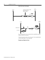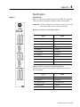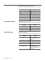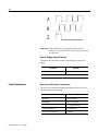
1
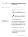
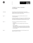
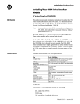
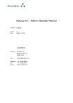
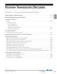
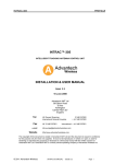
Allen-Bradley
REC
Resolver-toEncoder
Converter
(Cat. No. 4100-5.1)
Installation
and Setup
Manual
Important User
Information
Because of the variety of uses for the products described in this
publication, those responsible for the application and use of this control
equipment must satisfy themselves that all necessary steps have been
taken to assure that each application and use meets all performance and
safety requirements, including any applicable laws, regulations, codes
and standards.
The illustrations, charts, sample programs and layout examples shown
in this guide are intended solely for purposes of example. Since there
are many variables and requirements associated with any particular
installation, Allen-Bradley does not assume responsibility or liability
(to include intellectual property liability) for actual use based upon the
examples shown in this publication.
Allen-Bradley publication SGI-1.1, Safety Guidelines for the
Application, Installation, and Maintenance of Solid-State Control
(available from your local Allen-Bradley office), describes some
important differences between solid-state equipment and
electromechanical devices that should be taken into consideration when
applying products such as those described in this publication.
Reproduction of the contents of this copyrighted publication, in whole
or in part, without written permission of Allen-Bradley Company, Inc.,
is prohibited.
Throughout this manual we use notes to make you aware of safety
considerations.
!
ATTENTION: Identifies information about practices or
circumstances that can lead to personal injury or death,
property damage or economic loss.
Attention statements help you to:
• identify a hazard
• avoid the hazard
• recognize the consequences
Important: Identifies information that is critical for successful
application and understanding of the product.
GML, ULTRA, IMC, SCAN bus, Flex I/O, DTAM, PanelView, and SLC are trademarks; PLC is a registered
trademark of Allen-Bradley Company, Inc.
x-3
Table of Contents
Preface
Read This Manual ................................................1
Who Should Use this Manual............................... 1
Purpose of this Manual......................................... 1
Safety Precautions ................................................2
Contents of this Manual .....................................3
Related Documentation ......................................3
Terminology ......................................................... 3
Common Techniques Used in this Manual ..........4
Product Receiving & Storage Responsibility .......4
Allen-Bradley Support .........................................5
Local Product Support .......................................5
Technical Product Assistance ............................ 5
Chapter 1 – Overview
AEC Description ..................................................7
AEC Features ....................................................... 7
AEC Mechanical Specifications............................8
Chapter 2 – Installation & Hook-Up
Chapter Objectives ...............................................9
Installing the AEC ................................................9
Complying with European Union Directives .......9
EMC Directive ...................................................9
Mounting the AEC .............................................10
Connecting the AEC ...........................................13
Connecting the AEC to the 1394 ..................... 14
Connecting the AEC to the Compact ...............15
Wiring the AEC ..................................................16
Wiring Cable Flying Leads to the Plugs ..........16
The SSI Connector ........................................... 18
The Control Connector .....................................19
Fault Relay .....................................................19
Analog Servo Command Pass Through......... 21
Power Supply Connector ................................. 22
Publication 4100-5.2 - June 1998
ii
Table of Contents
Chapter 3 – Setup
Chapter Objectives .............................................25
Setting the Rotary Switches ............................... 25
Configuration Switch A ...................................26
Configuration Switch B ...................................26
Powering the AEC.............................................. 27
AEC With GML Commander ............................28
Adding AEC to your Commander Diagram ....28
Setting the Transducer Resolution .................28
Selecting Homing Procedure .........................29
Aligning Absolute Encoder ...........................29
Chapter 4 – Operation
Chapter Objectives .............................................31
Absolute Position Update ................................... 31
Incremental Position Output ...............................31
Position at Start-up .............................................32
Chapter 5 – Fault Indication & Control Status
Chapter Objectives .............................................33
Transducer Faults .............................................34
Encoder Faults ..................................................34
Internal Faults .................................................. 35
No Faults ..........................................................35
Appendix A – Specifications
Equivalent Circuit Diagrams ..............................39
Appendix B – Strobe Position For Applications Not
Using the 1394 or Compact
Absolute Strobe Cycle........................................ 43
Absolute Strobe Timing .....................................44
Incremental Strobe Period ..................................45
Index
Publication 4100-5.2 - June 1998
Preface
Preface
Read This Manual
Who Should Use this Manual
Read and understand this instruction manual. It provides the
necessary information to let you install, connect, and set up the AEC
for safe, reliable operation. This preface covers the following topics:
•
Who should use this manual
•
The purpose of this manual
•
Terms
•
Common techniques used in this manual
•
Allen-Bradley support
You should read this manual if you are responsible for the installation,
set up or operation of the AEC (Absolute Encoder Converter).
If you do not have a basic understanding of the products listed below,
contact your local Allen-Bradley representative for information on
available training courses before using this product.
Purpose of this Manual
•
S Class Compact motion controller
•
1394 GMC System module
•
GML (Graphic Motion Language) Commander software
This manual is an installation and set up guide for the REC (resolver
to encoder converter) and describes the procedures necessary to
properly install and configure it into your motion control system.
Publication 999-126 - February 1996
2
Preface
Safety Precautions
The following general precautions apply to the AEC:
ATTENTION: Electric shock can kill. Make sure the
AEC is safely installed in accordance with the Installation
and Set-up chapters of this manual. Avoid contact with
electrical wires and cabling while power is on. Only
trained service personnel should open the electrical
cabinet.
!
ATTENTION: This product contains stored energy
devices. To avoid hazard of electrical shock, verify that
all voltage on the capacitors has been discharged before
attempting to service, repair, or remove this unit. You
should only attempt the procedures in this manual if you
are qualified to do so and familiar with solid-state control
equipment and the safety procedures in publication NFPA
70E and BS-EN60204.
ATTENTION: The system integrator is responsible for
local safety and electrical codes.
!
ATTENTION: An incorrectly applied or installed
product can result in component damage or a reduction
in product life. Wiring or application errors, such as
undersizing or inadequate DC supply, or excessive
ambient temperatures can result in a malfunction.
ATTENTION: The AEC contains ESD (Electrostatic
Discharge) sensitive parts and assemblies. Static control
precautions are required when installing, testing,
servicing, or repairing this assembly. Component damage
can result if ESD control procedures are not followed. If
you are not familiar with static control procedures, refer
to Allen-Bradley publication 8000-4.5.2, Guarding
Against Electrostatic Damage or any other applicable
ESD Protection Handbook.
Publication 999-126 - February 1996
Preface
3
Contents of this Manual
Chapter
Title
Preface
1
Overview
2
Installation
3
Set-Up
Appendix Specifications
A
Contents
Describes the purpose, background, and scope of
this manual. Also specifies the audience for whom
this manual is intended.
Provides a general description of the REC, its
features and mechanical specifications.
Provides the steps needed to successfully mount
and wire the REC to a Resolver and the S Class
Compact Motion Controller or the 1394 GMC
system.
Provides the guidelines for setting up and
configuring the REC.
Provides physical, electrical, environmental, and
functional specifications for the AEC.
Related Documentation
The following documents contain additional information concerning
related Allen-Bradley products. To obtain a copy, contact your local
Allen-Bradley office or distributor.
For
Read This Document
Document Number
Programming Allen-Bradley motion controller with GML
GML Commander User Manual v4.01
GML Commander Reference Manual v4.01
GMLC-5.1
GMLC-5.2
Instructions for installation and set-up for the 1394 GMC system
1394 Digital, AC, Multi-Axis Motion Control
System User Manual
1394-5.0
Instructions for installation and set-up for the S Class Compact
motion controller
IMC S Class Compact Motion Controller
Installation and Set-up Manual
999-122
An article on wire sizes and types for grounding electrical
equipment (North American standards)
National Electrical Code
Published by the
National Fire Protection
Association of Boston,
MA.
An article on wire sizes and types for grounding electrical
equipment (European standards).
BS-EN 60204 Electrical Equipment of Machines
Published by British
Standards Institute
A complete listing of current Allen-Bradley documentation,
including ordering instructions. Also indicates whether the
documents are available on CD-ROM or in multi-languages
Allen-Bradley Publication Index
SD499
A glossary of industrial automation terms and abbreviations
Allen-Bradley Industrial Automation Glossary
AG-7.1
Terminology
The following terms are specific to this product. For a complete
listing of Allen-Bradley terminology, refer to the Allen-Bradley
Industrial Automation Glossary, (publication number AG-7.1).
Resolver Element - A small electrical mechanical device that has a
single winding on the rotor and a pair of windings on the stator that
are electrically positioned at right angles to each other. When the
rotor winding is excited with an AC reference signal, the stator
windings produce AC voltage outputs that vary in amplitude
according to the sine and cosine of the shaft position.
Publication 999-126 - February 1996
4
Preface
Resolver Package - An electrical mechanical device that has a single
input shaft and one or more resolver elements. The resolver elements
are geared to the input shaft.
Common Techniques Used in this
Manual
The following conventions are used throughout this manual:
•
Bulleted lists such as this one provide information, not procedural
steps.
•
Numbered lists provide sequential steps or hierarchical
information.
•
Words that you type or select appear in bold.
•
When we refer you to another location, the section name appears
in italics.
•
!
•
REC Product Receiving and
Storage Responsibility
ATTENTION: The exclamation point inside of a
triangle, followed by the word “ATTENTION”
indicate circumstances that can lead to personal
injury, death, property damage or economic loss.
Important:Identifies information that is critical for successful
application and understanding of the product.
You, the customer, are responsible for thoroughly inspecting the
equipment before accepting the shipment from the freight company.
Check the item(s) you receive against your purchase order. If any
items are obviously damaged, it is your responsibility to refuse
delivery until the freight agent has noted the damage on the freight
bill. Should you discover any concealed damage during unpacking,
you are responsible for notifying the freight agent. Leave the shipping
container intact and request that the freight agent make a visual
inspection of the equipment.
Leave the product in its shipping container prior to installation. If you
are not going to use the equipment for a period of time, store it:
•
in a clean, dry location
•
within an ambient temperature range of 0 to 85° C (32 to 185° F)
•
within a relative humidity range of 5% to 95%, non-condensing
•
in an area where it cannot be exposed to a corrosive atmosphere
•
in a non-construction area
Publication 999-126 - February 1996
Preface
Allen-Bradley Support
5
Allen-Bradley offers support services worldwide, with over 75 Sales/
Support Offices, 512 authorized Distributors and 260 authorized
Systems Integrators located throughout the United States alone, plus
Allen-Bradley representatives in every major country in the world.
Local Product Support
Contact your local Allen-Bradley representative for:
•
sales and order support
•
product technical training
•
warranty support
•
support service agreements
Technical Product Assistance
If you need to contact Allen-Bradley for technical assistance, please
review the information in this manual first. Then call your local
Allen-Bradley representative. For the quickest possible response, we
recommend that you have the catalog numbers of your products
available when you call. See the Related Documentation section of
this chapter for the publication numbers of other manuals that can
help with this product.
The Rockwell Automation Technical Support number is:
1-800-GMC-TECH
Publication 999-126 - February 1996
6
Preface
Publication 999-126 - February 1996
Chapter
1
Overview
REC Description
The REC converts a single or dual (Master/Vernier) resolver input
signal to an A Quad B quadrature encoder output signal. The A Quad
B quadrature output signal can be directly connected to the 1394
GMC System module or the S Class Compact motion controller.
In operation, the REC uses differential quadrature encoder output
signals to send incremental position data to the motion controller
based on the position of the resolver. Absolute position can be sent to
the motion controller for re-calibration.
The REC provides an independent fault detector with normally open
relay contacts and an LED indicator for each axis. The relay fault
outputs can be:
•
used to disable external devices in the event of a fault.
•
incorporated into the machine’s E-stop string.
•
incorporated into other protective circuitry.
The REC can trigger an encoder loss fault when it is used with the
1394 GMC system module or the S Class Compact.
REC Features
The REC has the following features:
•
Two AQB quadrature encoder output channels.
•
Two resolver input channels that support Allen–Bradley single or
dual resolver packages.
•
Resolution of 12 bits per resolver rotor rotation.
•
The ability to interface directly with the Allen–Bradley 1394
GMC System and the S Class Compact motion controller.
•
The ability to provide differential A and B quadrature encoder
output signals using 26C31 (or equivalent) driver IC.
•
A resolver phase loss circuit that detects the loss of resolver
signals.
•
Normally-open fault outputs for each encoder channel.
•
A watchdog LED for each encoder conversion channel.
•
An on-board reset switch that resets both axes.
•
An absolute home request that remotely clears corrected faults for
each axis independently.
•
A rugged steel housing with mounting tabs.
Publication 4100-5.2 - June 1998
8
Overview
REC Mechanical Specifications
•
The ability to be powered with a single18-36 V DC power supply.
•
Automatic resolver phase compensation for accurate position
tracking.
Figure 1.1 shows the placement and labeling of major items on the
REC front panel.
Figure 1.1
REC front panel
203.2 mm (8.0 in.) with cable clearance
Use 1/4-20 or M6
bolt (typical 2 places)
Reset
Axis 0
OK
Axis 1
OK
342.9 mm (13.5 in.)
330.2 mm (13.0 in.)
A
B
10
20
9
19
8
18
7
17
6
16
15
5
14
4
3
13
2
12
1
11
Axis 0 Resolver
Axis 0 Encoder
10
9
8
7
6
5
4
3
2
1
Power & Drives
Axis 1 Encoder
A
20
19
18
17
16
15
14
13
12
11
B
10
9
8
7
6
5
4
3
2
1
Axis 1 Resolver
REC
44.45 mm (1.75 in.)
Package size
mm and (in.)
Product weight
kg and (lbs.)
Material
Publication 4100-5.2 - June 1998
152.4 mm (6.0 in.)
Package Specifications
342.9 x 152.4 x 44.45
(13.5 x 6.0 x 1.75)
2.27
(5.0)
Painted Steel
Chapter
2
Installation & Hook-Up
Chapter Objectives
Read this entire chapter before beginning to mount, connect, or wire
any of the components to the REC. It is the responsibility of the
installer to see that the installation conforms to the directions in this
manual and local codes and procedures. This chapter covers the
following topics.
•
European Union Compliance
•
Mounting the REC.
•
Connecting the REC to the 1394 GMC system.
•
Connecting the REC to the Compact motion controller.
•
Wiring the REC to the resolver package.
•
Wiring the Power & Drives connector.
•
Wiring the drives signal for an S Class Compact.
•
Connecting a Fault relay.
Installing the REC
The REC is designed to mount in an electrical cabinet using the
flanges on its back panel. This installation method should be observed
for all applications. Before powering the REC, make sure it has been
configured correctly and that the resolver package, drives, and control
devices (controller) are connected to it correctly.
Complying with European Union
Directives
The information contained in this document pertains to the Resolverto-Encoder Converter (REC), an Allen-Bradley product. If the REC is
installed within the European Union or EEA regions and has the CE
mark, the following regulations apply.
EMC Directive
The REC is tested to meet Council Directive 89/336 Electromagnetic
Compatibility (EMC) in accordance with Article 10 (1). The
following directives apply:
•
EN 50081-2 EMC-Generic Emission Standard, Part 2-Industrial
Environment.
•
EN 50082-2 EMC-Generic Immunity Standard, Part 2-Industrial
Environment.
The REC, as described in this document, is intended for use in an
industrial environment and is not intended for use in a residential,
commercial, or light industrial environment.
Publication 999-126 - February 1996
10
Installation & Hook-Up
To meet CE requirements, the following are required:
Mounting the REC
•
The REC must be mounted in an IP 54 rated metal enclosure on a
metal panel.
•
All equipment must be bonded.
•
You must use the specified Allen-Bradley cables.
•
The REC is designed to function without maintenance when
operated in the environment specified in this manual.
•
Under normal conditions, the REC should not require any
periodic maintenance. However, if conditions are less than ideal
and any superficial dust has accumulated on the controller over
time, remove the dust carefully. Also, it is recommended to
periodically inspect all cables for abrasion and all connectors for
proper seating.
Before mounting the REC, verify that the 1394 GMC System or the S
Class Compact motion controller is installed correctly. Refer to the
1394 Digital AC Multi-Axis Motion Control System User Manual
(publication 1395-5.0) or the IMC 23/x Installation and Set-up
Manual (publication 999-122) for installation instructions.
The REC must be properly grounded to the metal enclosure panel. the
following diagram shows how to ground the REC to the panel.
Publication 999-126 - February 1996
Installation & Hook-Up
11
Figure 2.1
Mounting and Grounding Diagram
#10 AWG to
Ground Bus
REC Mounting Tab
Ground
Lug
Internal Star Washers
Size 1/4 - 20 or M6
Hardware
Tapped Hole
(Minimum of 3 Threads)
Scrape paint off panel to insure
electrical connection between
chassis and grounded metal plate.
Metal Panel
(Must be connected to
earth ground.)
Mount the REC next to a 1394 GMC system or an S Class Compact
motion controller on a metal enclosure panel using two 1/4 -20 or M6
bolts. Refer to the Mechanical Specifications in the Overview chapter
of this manual for mounting dimensions. Figures 2.2 and 2.3 in this
chapter show where to mount the REC.
!
ATTENTION: To avoid a shock hazard, remove all
power to the system panel before mounting the REC.
ATTENTION: The 1394 contains stored energy
devices. To avoid the hazard of electrical shock, verify
that all voltages are zero (0.00) before proceeding.
Publication 999-126 - February 1996
12
Installation & Hook-Up
Figure 2.2
Mounting the REC next to a 1394 GMC on a system panel
Wireway
REC
1394
GMC System
Reset
Axis 0
OK
A
Optional
Second
REC for
Axis 2 and 3
Axis 1
OK
B
Axis 0 Resolver
Axis 0 Encoder
Power & Drives
Axis 1 Encoder
A
B
Axis 1 Resolver
REC
Important: The REC can only be mounted on the left side (when
looking directly at the mounted 1394) of the 1394 GMC
System. This is due to cable specifications and module
expansion of the 1394.
Publication 999-126 - February 1996
Installation & Hook-Up
13
Figure 2.3
Mounting the REC next to an S Class Compact motion controller.
S Class
Compact
Allen –Bradley
Wireway
REC
IMC S Class
Reset
Axis 0
OK
A
The REC
can also
be placed
to the left
of the
Compact
Axis 1
OK
B
Axis 0 Resolver
Axis 0 Encoder
Optional
Second
REC for
Axis 2 and 3
Power & Drives
Axis 1 Encoder
A
B
Axis 1 Resolver
Axis 0
Axis 1
Servo and Servo and
Feedback Feedback
REC
Important: The REC can be mounted on either side of the S Class
Compact motion controller on the system panel.
Connecting the REC
The following section details how to connect the REC encoder
connectors to the 1394 GMC System and the S Class Compact
motion controller.
!
ATTENTION: Do not attempt to make any electrical
connections to the REC while power is applied. Doing
so risks damage to the REC, peripheral equipment, and
your health and safety.
Publication 999-126 - February 1996
14
Installation & Hook-Up
!
ATTENTION: The REC does not support the removal
or the insertion of any connectors when under power.
The power disturbance can result in unintended
machine motion, loss of process control, or an electrical
arc that can cause an explosion in a hazardous
environment.
Connecting the REC to the 1394
Connect the REC to a 1394 GMC System using the encoder cable
(catalog number 1394-GR04) for each axis. This is a four foot cable
that connects Axis 0 Encoder or Axis 1 Encoder connector on the
REC to the J3, J4, J5, or J10 encoder feedback connector on the 1394.
Important: This cable is polarity sensitive.
Important: The REC does not require power from the 1394 to
operate nor does it provide power to the 1394. However,
the 1394 requires a separate 5V power supply to run its
interface circuitry.
The 1394 interface circuitry requires 0.325A to operate. Any
additional devices connected to the 1394, such as incremental
encoders, can require an additional 0.2A per device (check your
device for the precise requirements).
To connect the encoder cables:
1. Insert the 12-pin plug labeled “REC/AEC” in the Axis 0 Encoder
or Axis 1 Encoder connector on the REC.
2. Insert the 12-pin plug labeled “1394” in the J3, J4, J5, or J10
encoder feedback connector on the 1394.
3. Wire the remaining auxiliary power labeled “ENC. PWR” to the
5V DC power supply. The red wire is +5V and the black is a +5
common.
Important: When using multiple Encoder devices, we recommend
you wire all of the auxiliary power cables to the same 5V
DC power supply.
Publication 999-126 - February 1996
Installation & Hook-Up
15
Figure 2.4
Connecting the Encoder Cables and the 5V Power Supply to the 1394
Wireway
REC
1394
GMC System
Reset
Axis 0
OK
A
Axis 0 Encoder Connector
Axis 1
OK
B
1394-GR04
Axis 0 Resolver
Axis 0 Encoder
Axis 1 Encoder Connector
Power & Drives
Axis 1 Encoder
5V DC
Power Supply
A
B
Axis 1 Resolver
REC
Important: Anchor the cable so that no more than 2 feet of cable is
left unsupported. The excessive weight of an unanchored
cable could pull the plug out of the connector.
Connecting the REC to the Compact
To connect the REC to the S Class Compact motion controller, use the
encoder cable (catalog number 4100-RCS3T) for each axis. This
three foot cable connects the Axis 0 Encoder or the Axis 1 Encoder
connector on the REC to the Axis 0, 1, 2, or 3 servo and feedback
connector on the S Class Compact. The Compact sends the drive
servo output signal through the 4100-RCS3T cable. Figure 2.4 shows
where to connect the encoder cable to the REC and the Compact.
Important: This cable is NOT polarity sensitive.
To connect the Encoder cable:
1. Insert one 12-pin plug in the Axis 0 Encoder or Axis 1 Encoder
connector on the REC.
2. Insert the remaining 12-pin plug in the Axis 0, 1, 2, or 3 servo and
feedback connector on the Compact.
Publication 999-126 - February 1996
16
Installation & Hook-Up
Figure 2.5
Connecting the Encoder Cables to the Compact
S-Class
Compact
Allen –Bradley
Wireway
REC
IMC S Class
Reset
Axis 0
OK
A
Axis 1
OK
B
4100-RCS3T
Axis 0 Resolver
Axis 0 Encoder Connector
Axis 0 Encoder
Axis 1 Encoder Connector
Power & Drives
Axis 1 Encoder
A
B
Axis 1 Resolver
Axis 0
Axis 2
Axis 1
Axis 3
Servo and Servo and Servo and Servo and
Feedback Feedback Feedback Feedback
REC
Important: Anchor the cable so that no more than 2 feet of cable is
left unsupported. The excessive weight of an unanchored
cable could pull the plug out of the connector.
Wiring the REC
The REC has two resolver connectors (Axis 0 Resolver and Axis 1
Resolver) that support single or dual resolvers. Each connector comes
with two removable 10-position plugs. The resolver cable flying leads
wire directly to the screw terminals on the plugs.
Wiring Cable Flying Leads to the Plugs
To wire the cable leads to the plug:
1. Look at the plug to make sure the terminal is open. Figure 2.5
shows both an open and a closed terminal.
Publication 999-126 - February 1996
Installation & Hook-Up
17
Figure 2.6
Terminal diagram
Terminal open
Clamping screws
Terminal closed
2.
Table 1: Terminal Steps
If the terminals are:
Do this:
Not open
Go to step 3
Open
Go to step 4
3. Using a small, flat-head screwdriver, turn the clamping screw
counter-clockwise several times.
4. Using a proper stripping tool, strip the wire insulation back on the
cable lead.
Important: All terminals accommodate a maximum of 14 gauge
wire.
5. Trim the cable lead so that 0.275 inches of metal wire is exposed.
6. Insert the cable lead in the appropriate terminal. Refer to the
proper figures for their locations.
7. Use the screwdriver to tighten the clamping screw to the proper
torque (0.25 N-m/2.2 in-lb.).
8. Verify that the cable lead does not pull out of the terminal.
9.
Table 2: Cable Leads
If the cable lead:
Do this:
Pulls out of the terminal
Repeat steps 3 through 9 again
Does not pull out of the terminal
Repeat steps 3 through 9 for the next
terminal
Publication 999-126 - February 1996
18
Installation & Hook-Up
Figure 2.7
Wiring a 1326AB-MOD-VD:256 Master/Vernier Dual Resolver package to the
Axis 0 Resolver plugs or the Axis 1 Resolver plugs on the REC.
Plug A
Plug B
Green N
Black R
20
19
18
16
15
14
Violet M
Black P
7
Blue J
Black K
5
6
4
Orange E
Black G
Resolver
Assembly
1326AB-MOD-VD :256
White A
Black B
3
13
2
12
11
9
Red D
Black F
8
17
Axis Fault
N.O.
10
Chassis Ground
Chassis Ground
1
1326-CVUxx Cable
Internal fault relay contact
Important: Anchor the cable so that no more than 2 feet of cable is
left unsupported. The excessive weight of an unanchored
cable could pull the plug out of the connector.
Figure 2.8
Wiring a 1326AB-MOD-VD x:x resolver package to the Axis 0 Resolver plugs
or the Axis 1 Resolver plugs on the REC
Plug A
20
19
Plug B
Red D
Black F
18
17
16
15
14
9
Resolver
Assembly
1326AB-MOD-VD x:x
8
Orange E
Black G
7
White A
Black B
5
13
Axis Fault
N.O.
10
6
4
3
12
2
11 Chassis Ground
1
Chassis Ground
1326-CVUxx Cable
Internal fault relay contact
Important: Anchor the cable so that no more than 2 feet of cable is
left unsupported. The excessive weight of an unanchored
cable could pull the plug out of the connector.
Publication 999-126 - February 1996
Installation & Hook-Up
19
Figure 2.9
Wiring an 846-SJxxxx-R2-x single resolver package to the Axis 0 Resolver
plug or the Axis 1 Resolver plug on the REC
Plug A
Plug B
Green E
Black G
20
19
18
16
White A
Black B
15
14
7
6
5
4
3
13
2
12
11
846-SJABCD-R2-E
Resolver Assembly
9
8
Red D
Black F
17
Axis Fault
N.O.
10
Chassis Ground
1
Chassis Ground
845AB-CA-i-xx Cable
Internal fault relay contact
Important: Anchor the cable so that no more than 2 feet of cable is
left unsupported. The excessive weight of an unanchored
cable could pull the plug out of the connector.
Connecting the Resolver to the Plug
After you have wired the resolver cable leads to the plugs, insert the
plugs in the resolver connectors on the REC. Figure 2.10 shows
where the resolver plugs connect to the REC.
Important: We designed and tested the REC to work with Allen–
Bradley resolver packages and cables up to 100 ft. If you
use longer cables, or cables other than those specified,
the product does not perform as specified.
Publication 999-126 - February 1996
20
Installation & Hook-Up
Figure 2.10
Connecting the Resolver Cable to the REC
Wireway
REC
Axis 0 resolver connector
Reset
Axis 0
OK
A
Axis 1
OK
B
Axis 0 Resolver
Axis 0 Encoder
Power & Drives
Axis 1 resolver connector
Axis 1 Encoder
A
B
Axis 1 Resolver
REC
To Resolver 1
To Resolver 0
Important: Anchor the cable so that no more than 2 feet of cable is
left unsupported. The excessive weight of an unanchored
cable could pull the plug out of the connector.
Wiring the Power and Drives
Connector
The Power & Drives connector comes with two removable 5-position
plugs. The connectors provide input power for the REC and the drive
reference signal outputs for the S Class Compact. Input power enters
the connector through the following pins:
•
pin 1 (18-36V DC)
•
Pin 6 (power ground)
•
Pin 7 (chasis ground)
Wire Requirements
The REC draws 12W maximum (0.5A at 24V DC). Use the
appropriate gauge wire to accommodate the current draw of the REC
while maintaining 18V DC minimum at the Power & Drives
connector (Refer to local wiring codes).
Important: The plug accommodates a maximum of 14 guage wire.
Publication 999-126 - February 1996
Installation & Hook-Up
21
Important: You must use both 5-position plugs when you power-up
the REC. We recommend you use twisted, shielded wire
that is UL listed. Refer to local wiring codes for more
information.
Power Supply Requirements
Use a 12W power supply with 24V DC output to power the REC. Use
a larger supply if you want to run multiple RECs or other devices.
Figure 2.11 shows where to connect the power supply ot the REC.
Important: Choose a power supply that complies with the
regulations and agencies in your area.
Figure 2.11
Wiring the Power Supply cable leads to the REC
Plug A
Plug B
10
5
9
4
8
3
7
2
6
1
24V DC
Power
Supply
18-36V DC
Power ground
Cable shield
Important: Anchor the cable so that no more than 2 feet of cable is
left unsupported. The excessive weight of an unanchored
cable could pull the plug out of the connector.
REC Internal Power Requirements
The REC converts the input power into its internal power
requirements using a DC-to-DC converter. The input power (500V
DC) is isolated from the internal circuitry and the chasis of the REC.
However, the common mode voltage of the input power with respect
to the chassis must not exceed +/- 100V DC.
Important: The REC is equipped with protection and filtering
circuits at various input, output, and power terminals.
You must earth ground the REC at a stable poiint for this
circuitry to operate properly. The earth ground is applied
to the REC through the chassis at the mounting tasbs of
the enclosure.
Publication 999-126 - February 1996
22
Installation & Hook-Up
Wiring the Drives Signal for a
Compact
When using the REC with an S Class Compact, the drive reference
signals (+/-10V) are passed from the Compact to the REC at
terminals 8, 9, and 10 on plug A (Axis 1), and at terminals 3, 4, and 5
on Plug B (Axis 0). To wire the drives signal:
1. Connect the drive signal to the servo amplifier using a twisted,
shielded cable (Belden 9501 or equivalent).
2. Wire the cable leads to the appropriate Power & Drives plugs ofr
the required axis. Figure 2.12 shows where to connect the drives
reference signals to the Power & Drives connector.
Both Axis 0 and Axis 1 can have drive signals present at their
connectors.
Note:
You do not need to wire the drive reference signal to the 1394
because it handles the reference signal output internally.
Figure 2.12
Wiring the Drive Reference Signal to an S Class Compact Motion Controller
Plug A
Plug B
10 1 Reference +
9 1 Reference 8 1 Reference Shield
5 0 Reference +
4 0 Reference 3 0 Reference Shield
7
2
6
1
Ref +
Servo
Amplifier
Axis 0
Ref -
Ref +
Servo
Amplifier
Axis 1
Ref -
Important: Anchor the cable so that no more than 2 feet of cable is
left unsupported. The excessive weight of an unanchored
cable could pull the plug out of the connector.
Connecting a Fault Relay
Publication 999-126 - February 1996
The REC is equipped with a fault detector that handles internal logic
voltage malfunctions and resolver phase loss faults. The fault detector
consists of:
•
An internal relay contact output that opens for each axis
•
An LED indicator that turns red for each axis
•
An encoder driver disabler for each axis
Installation & Hook-Up
23
The relay output can be used to disable external devices or
incorporated into your machine’s E-stop string (or other protective
circuitry) for fail-safe protection. The REC provides Form_C
(Normally Open) contacts to disable external equipment in the event
of a malfunction.
Important: Both the fault relay and the LED (Axis OK) are
activated during normal operation and deactivated during
a malfunction.
The fault output relay contacts are UL listed and CSA certified for 1A
at 30V DC. Figures 2.13 and 2.14 are examples of typical fault relays.
Figure 2.13
A typical Normally Open Fault status contact
24V DC
DC
Common
REC Fault contact
located at Axis 0,1
Resolver connector
Start
Stop
Start/Stop String
11
1
CR1
Fault String
CR1
Publication 999-126 - February 1996
24
Installation & Hook-Up
Figure 2.14
Typical Fault Relay for Switching AC
DC
Common
The REC Fault contact is located
at the Axis 0 and Axis 1
resolver connector
24V DC
11
1
K
AC
Common
AC Hot
Start
Stop
Start/Stop String
CR1
K
Fault String
CR1
We recommend that you use an external relay controlled by the REC
fault relay when you switch AC.
The fault connections shown above are typical. You can modify them
to fit the requirements of your application.
Encoder Loss Detection Circuit
Publication 999-126 - February 1996
Installation & Hook-Up
25
The 1394 GMC System and S Class Compact motion controller have
an encoder loss circuit that detects when the encoder drivers are
disabled. When the REC faults:
•
The REC disables the encoder drivers.
•
The REC signals an encoder loss fault ot the controller.
Important: The Transducer Loss Detection feature is an option in
the Edit Axis window in GML. We recommend that you
keep the transducer loss detection feature enabled in the
motion controller. Consult your motion controller’s
Installation and Setup Manual/User Manual and GML
Programming Manual for more information about how to
apply this feature.
Publication 999-126 - February 1996
26
Installation & Hook-Up
Publication 999-126 - February 1996
Chapter
3
Setup
Chapter Objectives
Adding the REC to your GML
Diagram
The REC was designed to complement the 1394 GMC System or the
S Class Compact motion controller and not intended to be used as a
stand-alone product. This manual assumes that you are running GML
(Graphical Motion Language) version 3.81 or greater and using
Firmware 3.3 or greater. This chapter contains the information you
need to:
•
Configure the motion controller using GML.
•
Align resolver packages.
•
Use a resolver package with a linear axis.
•
Define a non-zero home position.
Using the REC, the 1394 GMC System and S Class Compact can
support single resolver and dual resolver packages. Follow the
procedures below when you setup your GML diagram.
Selecting the REC as a Transducer
After you have defined your application in GML, select the REC as
your transducer. To select the REC:
1. From the menu bar, select Definitions. The Definitions menu
appears.
2. Select Axis Use. The Axis Configuration window appears.
3. Select the axis that interfaces with the REC resolver converter
output channel. A check mark appears next to the text.
4. Select Edit. The Axis Configuration edit window for the axis you
checked appears.
5. From the Transducer menu, select the REC. The word REC
appears in the field.
6.
If you are using a:
Go to:
1394 GMC System
Setting the Transducer Counts per
Motor Revolution for the 1394
S Class Compact motion controller
Setting the Homing Position
Publication 999-126 - February 1996
26
Setup
Setting the Transducer Counts per Motor Revolution for the 1394
You have to adjust the Transducer Counts per Motor Revolution
parameter when you use an external transducer to close the servo
position loop. This parameter is used to scale internal variables for
tuning the axis.
With the Axis Configuration edit window open, set the transducer
counts per motor revolution. To set the transducer counts per motor
revolution:
1. From the Configuration menu, select Drive/Motor 1394.
Note: If a GML Info window appears, note the information and select
OK.
2. Enter a value in the Transducer Counts/Mtr Rev field.
If the Ratio:
Do this:
between the motor shaft and the
resolver package input shaft si 1:1
Enter 4096
between the motor shaft and the
resolver package input shaft is not
1:1
Adjust the value to compensate for
the ratio (refer to the examples for
more information).
For Example: If the motor shaft to resolver package shaft gear ration
is 10:1 (every time the resolver package shaft makes one revolution,
the motor shaft makes ten.), enter 409.6. Please note that this example
is valid for single/dual packages that have a resolver element to input
package shaft gear ration of 1:1.
For Example: If the resolver package to resolver element shaft gear
ratio is 2.5:1 (every time the internal resolver element makes one
revolution, the resolver package shaft makes 2.5) and the motor shaft
to resolver package shaft is 10:1 (every time the resolver package
shaft makes one revolution the motor makes ten) enter ((4096/2.5) /
10) = 163.84.
3. Go to Selecting the Homing Procedure.
Selecting the Homing Procedure
With the Axis Configuration edit window open, set the homing
position. To set the homing position:
1. From the Configure menu, select Homing. The homing options
appear.
Publication 999-126 - February 1996
Setup
27
2.
If your system uses a:
Select:
Single resolver package
Absolute
Dual resolver package
Absolute_MV
If you select Absolute_MV, an Assembly Part # menu that contains a
list of supported Allen-Bradley dual resolver part number appears.
Note: Currently, the REC supports the 1326AB-MOD-VD 256/255
dual resolver package.
The Custom menu choice ( located in the Assembly Part # menu)
allows you to enter a custom master/vernier dual resolver turns range.
Currently, the REC supports the 1326AB-MOD-VD 256/255 resolver
with a turns range of 256. Allen-Bradley is reserving the Custom
menu choice for future dual resolver packages. if you want to use a
master/vernier resolver other than the 1326AB-MOD-VD 256/255
dual resolver package consult Allen-Bradley to verify that it is
supported.
Setting the Transducer Position Units
With the Axis window still open, set the transducer position units. To
set the transducer position units:
1. From the Configure menu, select Position Units. The Position
Units options appear.
2. Enter a value into the Transducer Counts/Unit field.
The units you enter into the Position Units field depend on the
application. When you use the REC, it is important to know the
number of counts received from the transducer per position unit.
The REC sends 4096 counts to the motion controller per resolver
element revolution and dual resolver package shaft revolution.
3. When you are finished making all of your modifications, select
Save. The Axis window disappears.
Publication 999-126 - February 1996
28
Setup
On-Line Axis Setups
Axis hookup and servo parameters can be readily handled through the
GML On-Line Manager Setup functions. For example, the Motor/
Encoder Test and the Align Absolute Transducer procedure are just
two of the functions that can be controlled using GML. The On-Line
Manager provides you with an interactive means of setting up your
motion controller axes. The sections below show how to use these
functions to help setup the REC. Refer to your controller’s
Installation and Setup Manual/User Guide and GML Programming
Manual for more information on how to use the On-Line Setup
functions.
Important: Before you proceed with On-Line Setups, verify that the
REC is installed correctly and that the GML program is
configured properly.
Selecting Axis/Drive Data Downloads
Before you proceed with On-Line setups you have to download your
GML diagram to the motion controller so that the information
contained in the diagram can be made available to the motion
controller.
To transfer the axis specific setup parameters from the diagram to the
motion controller, you have to select the Axis/Drive Data Downloads
option in GML before you download the diagram. To select Axis/
Drive Data Downloads:
1. From the menu bar, select Definitions. The Definitions window
appears.
2. Select Control Options. The Control Options window appears.
3. Select Axis/Drive Data Downloads. An X appears next to the
text.
4. Select Save. The Control Options window disappears.
Running a Motor/Encoder Test
Use the Motor/Encoder Test to check the electrical connection of the
servo drive and encoder interface and to establish the correct
rotational direction of the servo drive and encoder. Establishing these
motor and encoder polarities helps prevent runaway axis when the
feedback loop is closed. To select a Motor/Encoder Test:
1. From the menu bar, select Diagram. The Diagram menu appears.
2. Select Online. The Online Manager window appears.
3. Select Download Diagram. The program downloads to the controller.
4. When the download is finished, select Enter Setups. The Do Setups window appears.
Publication 999-126 - February 1996
Setup
29
5. Select Motor/Encoder Test. A black circle appears in the radio
dial next to the text.
6. Select Execute. Refer to your GML Programming Manual and
your motion controller’s Installation and Setup/User Manual for
more information on Motor/Encoder Tests.
Aligning the Absolute Transducer
After you have completed the Motor/Encoder Test, you need to align
the resolver package position to the axis position. Using the Align
Absolute Transducer procedure, you can randomly attach the
transducer to the physical axis. You do not need to match the actual
position of the resolver package to the actual position of the axis
because the alignment routine reads the position relative to the actual
position of the axis and then compensates this position relative to the
actual position of the axis. After the alignment procedure completes
successfully, the axis and resolver package are adjusted to read zero at
this position.
If you are using a dual resolver package, the alignment procedure will
also synchronize both internal resolver elements by electronically
offsetting them to zero. This eliminates the need for the user to
manually perform this procedure. To align the absolute transducer:
1. Select Align Absolute Transducer. A black dot appears in the
radio dial next to the text.
Important: If the axis is not still when you align or home the
resolver package the position information will be
incorrect. The axis must be still before performing the
alignment procedure.
Important: When executing the alignment procedure on a servo
axis, feedback is momentarily disabled and then enabled
again (if the error checking features do not detect an
error) in the motion controller. If the axis has stored
energy or the ability to move during the time feedback is
disabled, you have to apply a breaking mechanism to the
axis before you execute an alignment routine.
For single resolver packages, the alignment routine reads the absolute
position of the transducer. If no encoder noise or loss faults occur, the
routine completes successfully. The motion controller negates the
read position and stores it in its working memory. For absolute
devices, the home position is used as a home offset and is added to the
transducer’s actual position during a homing command.
Publication 999-126 - February 1996
30
Setup
For Example: Assume the actual position of the absolute transducer
is 1 at the alignment point. After alignment, the home position (home
offset) variable equals -1. Therefore, the axis position is defined as 1
+ (-1) = 0. Assume the axis is moved one unit and the position of the
absolute transducer is now 2. If you execute a home command at this
point, the axis position is 2 + (-1) =1.
For dual resolver packages the alignment routine uses the home
position and a transparent parameter called Vernier Offset to calculate
the alignment position. The Home Position stores the master resolver
element position offset and Vernier Offset stores the vernier resolver
element offset.
2. Select Execute.
If:
Do this:
The Align Absolute Transducer
window appears
Go to step 3
A GML Error window appears
1. Check your application program.
2. Check your REC installation
procedures.
3. Move the axis to its minimum travel position. The alignment routine will define this position as zero.
4. Select OK to align the position to zero.
5. While the alignment routine is running, verify that you have
selected the proper absolute device (the absolute device you
selected shows up in the window that appears while the axis is
aligning).
6.
If the transducer alignment:
Do this:
Was successful
1. Select OK
2. Go to the Updating the Diagram
section.
Was unsuccessful
Check your GML diagram.
Updating the Diagram
Once the Alignment routine completes successfully, the resolver
offsets (Home Position and Vernier Offset) and axis specific
information gathered during on-line setups is stored in the motion
controller’s working memory. You must update your diagram to
include your latest changes.
To update your diagram:
Publication 999-126 - February 1996
Setup
31
1. While still in the Enter Setups window, select Tuning Complete,
Save Data/Update Diagram.
2. Select Execute. The diagram updates and the Do Setups window
disappears.
3. Select Exit Online. The Online Manager window disappears.
Homing the Axis
The motion controller executes a home command to determine the
absolute position of the resolver package. To execute the home axis
command:
1. Double click on the Home Axis block in your GML diagram.
2. Select Wait for Completion. An X appears in the check box.
3. Select Save. The Home Axis window disappears.
Important: Before you use any of the position information sent by
the REC, you have to home the axis because the home
command configures the REC for single resolver or dual
resolver package applications.
Important: When executing the homing procedure on a servo axis,
feedback is momentarily disabled then enabled again ( if
the error checking features do not detect an error) in the
motion controller. If the axis has stored energy or the
ability to move during the time feedback is disabled, you
have to apply a breaking mechanism to the axis before
you execute a homing routine.
Important: If the axis is not still when you home a dual resolver
package, the position information will be incorrect.
Depending on your application, a breaking mechanism
may be required to stabilize the axis before you execute a
home command in the motion controller.
Using a Resolver Package with a
Linear Axis
If you installed and configured your system for a dual resolver
package, you can set the axis for linear positioning. When you define
the axis to be linear, the 256 turn dual resolver package’s internal
absolute travel range is:
-5 <travel<=251 turns
The motion controller uses a home command to determine the
absolute position of the axis. After a home command, the REC
incrementally reports any movements back to the motion controller.
This new information builds upon the absolute value obtained during
homing and can cause the position of the axis to exceed the range in
either direction. However, during an absolute home command, the
initial absolute position of the 256 turn dual resolver package can
only be obtained within the range above.
Publication 999-126 - February 1996
32
Setup
If the travel range was defined to be 0 =< travel <256 and the axis
homed, after moving it slightly negative of the (zero) position, the
controller would think that the axis was near 256 instead of near zero.
The internal travel range allows the axis to dither about zero by -5
turns thus eliminating unwanted roll over at the alignment position. If
you homed the axis after moving it slightly negative of -5 the axis
position would roll over to just less than 251.
When you use a single resolver, the absolute travel range is 0 <=
travel < 1 turns (for geared resolver packages with a 1:1 gear ratio).
There is no built-in procedure implemented in the control to handle
dither about the alignment (zero) position. If you desire a dither
feature, you can use the algorithm shown below to program a dither
value. This value is typically a small percentage of the travel range.
Inside a Home block select:
•Normal
•Wait for Completion
Inside an If block build the expression:
•Actual Position >= (1 + dither value)
Inside the Redefine Position block:
•Select Relative
•Select Actual
•Enter -1
Defining a Non-Zero Home Position
When you align the transducer to the physical axis using the Align
Absolute Transducer routine, the routine adjusts the home position to
offset the transducer position to zero.
Important: We recommend that you do not change the home
position established by the Align Absolute Transducer
routine.
You can establish a non-zero reference point using the GML Redefine
Position command after a Home command.
Defining the Redefine Position Command
After you have executed the home command, you need to define the
Redefine Position Command. To define the Redefine Position
Command:
1. Create a Redefine Position block and place it next to the Home
Axis block.
2. Double-click on the Redefine Position block.
Publication 999-126 - February 1996
Setup
33
3. Select the axis you are configuring. The name of the axis appears
in the field.
4. Select Relative from the Mode menu. The word Relative appears
in the field.
Note: This feature compensates for any dither that may occur while
executing the program
5. Select Actual from the Position menu. The word Actual appears
in the field.
6. Enter a positive or negative value to redefine the current actual
position.
Note: If the axis was previously aligned to zero, the actual position
is zero.
7. Select Save. The Redefine Position window disappears.
Publication 999-126 - February 1996
34
Setup
Publication 999-126 - February 1996
Appendix
A
Specifications
Figure A.6
AEC Front Panel
Figure A.1 shows the terminal locations for the REC. The following
tables provide the pin numbers and their respective descriptions.
Important: Refer to Wiring Axis 0 and Axis 1 Resolvers for wiring
your Allen-Bradley resolver package to the REC.
Resolver Connector Terminal Description
Plug A
Plug B
20 = Cosine high
10 = Cosine high
19 = Cosine low
9 = Cosine low
18 = Stator shields
8 = Stator shields
17 = Sine high
7 = Sine high
16 = Sine low
6 = Sine low
15 = Cosine high
5 = Cosine high
14 = Rotor low
4 = Rotor low
13 = Rotor shield
3 = Rotor shield
12 = Chassis ground
2 = Chassis ground
11 = Fault normally open
1 = Fault common
Power & Drives Connector Terminal Descriptions
The table below shows the terminal descriptions for the Power &
Drives connector.
Plug A
Plug B
10 = 1 Reference +
5 = 0 Reference +
9 = 1 Reference -
4 = 0 Reference -
8 = 1 Reference shield
3 = 0 Reference shield
7 = Chassis ground
2 = Not Used
6 = Power ground
1 = 18-36V DC
Publication 4100-5.2 - June 1998
38
Encoder Connector Terminal Descriptions
The table below shows the terminal descriptions for Axis 0 and Axis
1.
A
Environmental Specifications
B
12 = Z -
6=Z+
11 = B -
5=B+
10 = A -
4=A+
9 = Strobe -
3 = No Connection
8 = Reference Shield Input
2 = Strobe +
7 = Reference - Input
1 = Reference + Input
Operating and Storage Conditions
The table below details the environmental specifications of the REC
Specification
Electrical Specifications
Operating Temperature
0 to 60 o C
Storage Temperature
-40 to 70 o C
Humidity
95% non condensing @ 60 o C
Resolver Specifications
The table below details the electrical specifications for the resolver.
Specification
Publication 4100-5.2 - June 1998
Description
Description
Number of resolver inputs
2 conversion channels, each capable of
supporting single or dual resolver
packages
Resolver type
Transmitter (rotor primary)
Excitation amplitude
4.77V rms +5% at a 4000Hz +20%
Resolver transformation ratio
0.45 to 1 Strator to Rotor +5% Zss =
275 Ohms
Maximum Resolver phase shift
Each conversion channel selfcompensates within the range of +/- 25
degrees maximum resolver phase shift
( rotor to strator).
39
Specification
Description
1326AB-MOD-VD1:x single resolver
package.
x = rotor to input shaft ration
x = 1, 2, 2.5, or 5
1326AB-MOD-VD:256/255 dual
resolver package.
256/255 is the master to vernier gear
ratio.
Use cable 1326AB-CVUxx for the
specified Bulletin 1326 resolver
packages above.
xx = length in feet (100 ft. maximum)
Supported resolver packages
846-SJ abcd-R2-e single resolver
package.
a = mounting configuration
b = connector style
c = connector location
d = gear ratios
R2 = Harlowe resolver element
11BRCX-300-C or equivalent. e
replaces c if mating connector is
supplied.
Use cable 845AB-CA-i-xx
xx = length in feet (up to 100 ft.)
Strobe Inputs:
Type
Source Impedance
Maximum active Voltage
Minimum Inactive Voltage
Current Sourcing Active Low
10k Ohm
0.6V DC
2.2V DC
Encoder Output Specifications
The table below details the electrical specifications of the encoder
output.
Specification
Number of encoder outputs
Type of encoder output
Equivalent line count
Maximum update rate
Marker output
Description
2 (0 and 1)
Incremental quadrature with marker, EIA RS 422 level
4096 counts under 4X decode mode
1.6 MHz
Synchronized 180 degrees to A channel. See figure A.2
for a picture of the output for the three channels
Figure A.7
Marker Output
Publication 4100-5.2 - June 1998
40
A
B
Z
Important: The marker pulse is synchronized to the resolver
element’s zero position which is not necessarily the axis
zero position.
Power Supply Specifications
The table below details the electrical specifications of the power
supply.
Specification
power input requirements
Description
18 to 36 V DC at 12W maximum
Note: Input has reverse polarity protection
Product Performance
Resolver-to-Encoder Conversion
The table below details the product performance of the resolver-toencoder conversion for the REC.
Specification
Publication 4100-5.2 - June 1998
Description
Resolution
12 bits per revolution
Repeatability
1 LSB (5.3 arc minutes)
Acceleration error
5.6 e -3 LSBs at 100 rev/sec2
Dynamic following error
5 LSBs at 6000 RPM
Resolver element shaft speed
0 to 6000 RPM
41
Excitation Oscillator
The table below details the product performance of the excitation
oscillator for the REC.
Specification
Description
Excitation Frequency
4000Hz at +25%
Amplitude
4.77V rms +5%
Phase Loss Detection
The table below details the product performance of the phase loss
detection circuit for the REC.
Specification
Purpose
Description
To detect loss of resolver signals.
When fault occurs:
•
The status indication LED turns
from green to red
•
The 30V DC 2A/125V AC
0.6A rated relay contact output
opens
•
The motion controller detects
loss of feedback
Action
After the problem is corrected, you can
clear the fault for each axis by: pushing
the reset button on the REC or by using
a home request from the motion
controller
Response range
0 < resolver shaft speed < 6000 rpm
Response Time
The phase loss detection circuit will
respond within 180 degrees of resolver
element rotation as long as you use no
more than 100ft of specified cable.
Resolver inputs
The REC has been designed to use
Allen-Bradley Bulletin 846 and 1326
absolute feedback packages that
feature Harlowe 11BRCX-300-C or
equivalent resolver elements.
The 4.77V rms excitation amplitude has
been adjusted so that when you use the
resolvers listed above with the REC the
strators receive 2V rms +10%.
Publication 4100-5.2 - June 1998
42
Publication 4100-5.2 - June 1998
Index
Index
A
Absolute Position Update, 31
Absolute Strobe Cycle, 43
Absolute Strobe Timing, 44
C
CE requirements, 10
Configuration
GML Commander
Adding to a Commander
Diagram, 28
Aligning Absolute Encoder, 29
Selecting Homing Procedure, 29
Setting the Transducer
Resolution, 28
Connecting the AEC
to the 1394, 14
to the Compact, 15
D
Definitions
encoder, 4
transducer, 3
Description, 7
E
European Union Directives
EMC Directive, 9
F
Fault Indication
Encoder Faults, 34
Internal Faults, 35
No Faults, 35
Transducer Faults, 34
Features List, 7
Fuse, 27
I
Incremental Position Output, 31
Incremental Strobe Period, 45
M
Mounting the AEC
next to a 1394, 12
next to a Compact, 13
P
Pin Functions
Control Connector, 21
Power Supply, 22
SSI Connector, 18
Pin Numbering
Control Connector, 21
Power Supply, 23
SSI Connector, 18
Position at Start-up, 32
Powering the AEC, 30
R
Related Documentation 3
Rotary Switches
Setting, 25
Switch A, 26
Switch B, 26
S
Specifications
Connector Locations
Control, 37
Encoder, 37
Power, 38
SSI, 37
Environmental, 38
Mechanical, 38
Mechanical,
Module, 38
Package, 8
Pin Numbers, 37
Strobe Position
Absolute Position Transfer
Protocol, 44
Absolute Position Transfer
Timing, 44
Incremental Strobe Period
Protocol, 46
Incremental Strobe Timing
Period, 46
Support
Publication 4100-5.2 - June 1998
48
Index
Allen-Bradley, 5
local product, 5
technical product assistance, 5
W
Wiring
Cable Flying Leads, 16
Control Connector
Analog Servo, 21
Fault Relay 19
Power Supply, 22
SSI Connector, 18
Publication 4100-5.2 - June 1998
Allen-Bradley, a Rockwell Automation Business, has been helping its customers improve
productivity and quality for more than 90 years. We design, manufacture and support a broad
range of automation products worldwide. They include logic processors, power and motion
control devices, operator interfaces, sensors and a variety of software. Rockwell is one of the
world’s leading technology companies.
Worldwide representation.
Argentina • Australia • Austria • Bahrain • Belgium • Brazil • Bulgaria • Canada • Chile • China, PRC • Colombia • Costa Rica • Croatia • Cyprus • Czech Republic •
Denmark • Ecuador • Egypt • El Salvador • Finland • France • Germany • Greece • Guatemala • Honduras • Hong Kong • Hungary • Iceland • India • Indonesia •
Ireland • Israel • Italy • Jamaica • Japan • Jordan • Korea • Kuwait • Lebanon • Malaysia • Mexico • Netherlands • New Zealand • Norway • Pakistan • Peru •
Philippines • Poland • Portugal • Puerto Rico • Qatar • Romania • Russia-CIS • Saudi Arabia • Singapore • Slovakia • Slovenia • South Africa, Republic • Spain •
Sweden • Switzerland • Taiwan • Thailand • Turkey • United Arab Emirates • United Kingdom • United States • Uruguay • Venezuela • Yugoslavia
Allen-Bradley Headquarters, 1201 South Second Street, Milwaukee, WI 53204 USA, Tel: (1) 414 382-2000 Fax: (1) 414 382-4444
Publication 4100-5.1 – June 1998
Supercedes Publication 999-126 February 1996
PN 999-126
Copyright 1998 Allen-Bradley Company, Inc. Printed in USA