1
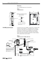
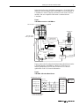
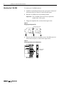
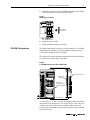
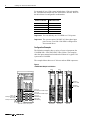
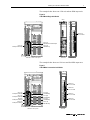
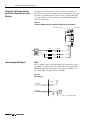
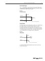
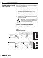
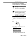
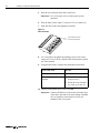
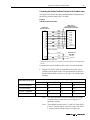
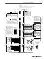
Installation Instructions Installing Your 1394 Drive Interface Module (Catalog Number 1394-DIM) Introduction This publication provides installation instructions for adding the 1394 Drive Interface Module to your 1394 system. Use these instructions in conjunction with the 1394 Digital, AC, Multi-Axis Motion Control System User Manual (publication 1394-5.0). Note: For instructions on using GML Commander to configure your 1394-DIM, refer to the GML Commander Reference Manual (publication GMLC-5.2). The 1394-DIM acts as an interface between one 1394 GMC/GMC Turbo system module and an external axis drive(s). On the 1394x-SJTxx-C, -C-RL, -T, and -T-RL, the 1394-DIM acts in place of one to four axis modules. On the 1394C-SJTxx-L and -L-RL the 1394-DIM acts in place of one axis module. The 1394-DIM passes a standard servo output signal from the system module to each external drive connected to the 1394-DIM. Using a 1394-DIM as part of a 1394 system lets you control external drives and motors of any size. Specifications The table below lists the 1394-DIM specifications. The: For the 1394-DIM is: Firmware version 3.7 or higher with 1394x-SJTxx-C-xx and -T-xx systems 3.9 or higher with 1394C-SJTxx-L-xx systems GML Commander, version 4.01 or higher 24V, 50 kHz provided by the 1394x-SJT-xx system module Software Input voltage Analog output information (Px-1,2) Voltage Signal isolation Resolution Impedance Offset Drive OK Drive enable output Operating temperature Relative humidity Weight 0 to ± 10V analog 1500V rms 12 bits, 4.88 mV 220 ohms ± 80 mV maximum, compensated to 0 through software setup 15V DC @ 5 mA supplied by the DIM 30V DC @ 1 A 0° to 50° C (32° to 122° F) 5-95% 3 kg (6.6 lb) Certification The certified 1394-DIM product displays the following: • UL Listed (File E59272) • CUL Listed • CE marked for all applicable directives Publication 1394-5.12 — December 1999 2 Installing Your 1394 Drive Interface Module Dimensions The 1394-DIM dimensions are shown below. Figure 1 1394-DIM Dimensions 25.0 (0.98) 280 (11.02) 8.0 (0.32) Dimensions are in millimeters and (inches) Mounting Hole Detail 400.0 (15.75) 8.0 (0.31) 350 (13.78) 10.1 (0.40) 385.0 (fastener (15.16) 350.0 (13.78) location)1 15.9 (0.63) 8.0 (0.31) 12.0 (0.47) All slots accept M6 or 1/4-20 mtg. screws 1 Dimension shown is for mounting hardware location and does not reflect the location of the lower slot radius. 50.0 (1.97) 1394-DIM System Examples In the figure below, the 1394-DIM is connected to a 1394 GMC Turbo with two 1394 axis modules. A 1326AB-Bxxxx motor is directly connected to each of the 1394 axis modules. Two servo amplifiers with motors are connected to the 1394-DIM. It can accept two because there are two axis modules connected to the 1394 GMC Turbo. The encoders attached to the motors have encoder feedback cables connected to the system module. Figure 2 1394-DIM Connected to a GMC or GMC Turbo 1394-DIM 1394 Axis Modules 1394-DIM ground connector 1394 GMC or GMC Turbo System Module DIM A axis connector GML Axis 1 Axis 0 See Figure 19 for Auxiliary Encoder input pin-outs and Figure 20 to view the Auxiliary Encoder Connectors on a bottom view of the 1394 GMC/GMC Turbo system module. ns ectio conn Axis d on the IM locate side of D r unde 1326AB DIM B axis connector Status RS-232/-422 +/- 10V reference Drive Enable Drive OK (see Figure 16) Servo Amplifier Encoder Servo Amplifier 1326AB Motor Encoder 1394-GE15 Encoder Feedback Cable Encoder Feedback Cable Publication 1394-5.12 December 1999 1326-CEU-xxx (if A-B 845H) Motor Installing Your 1394 Drive Interface Module 3 In the figure below, the 1394-DIM is connected to a 1394 GMC Turbo with two 1394 axis modules and a 1398-DDM-xxx servo controller. A 1326AB-Bxxxx motor is directly connected to each of the 1394 axis modules. One servo amplifier with motor is connected to the 1394-DIM. Figure 3 1394-DIM Connected to a 1398-DDM-xxx 1394 Axis Modules 1394-DIM 1398-DDM-xxx Status J5 1394 GMC or GMC Turbo System Module J2 Axis 0 Axis 1 Axis 2 TB1 J1 Breakout Board (Refer to Figure 4) Encoder 1326AB J2 J1 Motor Power 9101-1391 J1 ! ? H, F, Y, or N Series Motor Encoder 1326-CEU-xxx (If A-B 845H) Encoder 1326AB 1394-GE15 1326-CEU-xxx (If A-B 845H) J2 Breakout Board 9101-1392 Figure 4 shows the J1 breakout board interconnect details between the 1394-DIM and the 1398-DDM-xxx. Refer to ULTRA 200 User Manual (publication 1398-5.0) and ULTRA 100 User Manual (publication 1398-5.2) for more information. Figure 4 1394-DIM to J1 Breakout Board Pinouts 1394-DIM Cable Connector 2 Belden 8163 cable or equivalent J1 Breakout Board J1-5 + Analog Out Px-1 J1-6 J1-22 CMND + – Analog Out Px-2 J1-23 CMND - – Drive Enable Px-3 J1-20 Enable + Drive Enable Px-4 J1-26 I/O PWR + DROK Px-5 J1-25 Ready - – DROK Px-6 J1-24 Ready + 24V I/O Power Supply 1 Shield Px-7 1 Required on ULTRA 100 only 2 x = axis controlled by DIM Publication 1394-5.12 December 1999 4 Installing Your 1394 Drive Interface Module Mounting Your 1394-DIM To mount your 1394-DIM hardware: 1. Install the top mounting fastener on the system panel. The head of the fastener must be at least 0.25 inches from the panel. 2. Hang the 1394-DIM on the top mounting fastener. Important: The 1394-DIM must be the last (or right-most) module in the 1394 system. 3. Engage the alignment tabs, as shown in the figure below. Figure 5 Engaging the Alignment Tab Engaged alignment tab 4. Slide the slide-and-lock mechanism on the 1394-DIM to the left until it locks into place, as shown in the figure below. Figure 6 Attaching the Slide-and-Lock Mechanism Slide-and-lock mechanism Publication 1394-5.12 December 1999 Installing Your 1394 Drive Interface Module 5 5. Attach the terminator to the 1394-DIM and slide it to the left until it locks into place, as shown in the figure below. Figure 7 Attaching the Terminator Attaching the Terminator 6. Install the lower fastener. 7. Tighten the upper and lower fasteners. 1394-DIM Configurations The identity and number of the axes you can connect to a 1394-DIM depends upon the number of 1394 axis modules connected to your 1394 system in addition to the 1394-DIM. The figure below shows the input connections located on the bottom of a typical 1394 system and a 1394-DIM. Figure 8 A 1394-DIM Connected to a GMC or GMC Turbo Front of the units 1394-DIM ground connector Bottom of the 1394-DIM Bottom of the 1394 GMC or 1394 GMC Turbo System Rear of the units A 1394x-SJTxx-C, -C-RL, -T, and -T-RL system module can control a maximum of four physical axes. The 1394C-SJTxx-L and -L-RL can control only one axis. Each 1394 axis module added to the 1394 system reduces the number of external drives and axes the 1394-DIM can control by one. Publication 1394-5.12 December 1999 6 Installing Your 1394 Drive Interface Module For example, if your 1394 system includes three 1394 axis modules, the 1394-DIM can control only one external drive and axis. Refer to the table below for configuration combinations. Maximum number of DIM-controlled axes: Number of 1394 axes: 4 3 2 1 0 0 1 2 3 4 Important: You can add only one 1394-DIM to a 1394 system. Important: The system requires 360/480V AC three-phase input power to run, even if the 1394-DIM is configured for four external drives. Configuration Examples The following examples show a variety of ways to incorporate the 1394-DIM into a 1394 GMC/GMC Turbo System. The examples show the input connections located on the bottom of a typical 1394 system and a 1394-DIM. The example below shows two 1394 axes and two DIM output axes. Figure 9 1394-DIM with Multiple Axis Modules Axis 0 Axis 1 7 1 7 1 Axis 0 (J5) Motor Resolver Feedback Input Axis 1 (J6) Motor Resolver Feedback Input Axis 2 (J7) 1394 DIM Plug Axis 3 (J10) 1394 DIM Plug Axis 2 (J5) Auxillary Encoder Input Axis 3 (J10) Auxillary Encoder Input 1394 GMC or GMC Turbo System Publication 1394-5.12 December 1999 1394x-AMxx 1394x-AMxx 1394-DIM DIM Axis A Axis 2 on 1394 DIM Axis B Axis 3 on 1394 Installing Your 1394 Drive Interface Module 7 The example below shows one 1394 axis and one DIM output axis. Figure 10 1394-DIM with Single Axis Module Axis 0 7 1 DIM Axis A Axis 1 on 1394 Axis 0 (J5) Motor Resolver Feedback Input Axis 1 (J4) Auxillary Encoder Input Axis 1 (J6) 1394 DIM Plug 1394x-AMxx 1394 GMC or GMC Turbo System 1394-DIM The example below shows no 1394 axes and four DIM output axes. Figure 11 1394-DIM Not Connected to Axis Module 7 1 7 1 Axis 0 (J3) Auxillary Encoder Input Axis 2 (J5) Auxillary Encoder Input Axis 1 (J6) 1394 DIM Plug Axis 2 (J7) 1394 DIM Plug Axis 3 (J10) Auxillary Encoder Input Axis 3 (10) 1394 DIM Plug 1394 GMC Turbo System DIM Axis B Axis 1 on 1394 7 Axis 0 (J5) 1394 DIM Plug Axis 1 (J4) Auxillary Encoder Input DIM Axis A Axis 0 on 1394 1 7 1 DIM Axis C Axis 2 on 1394 DIM Axis D Axis 3 on 1394 1394-DIM Publication 1394-5.12 December 1999 8 Installing Your 1394 Drive Interface Module Wiring the 1394 System Module Input Power When Not Using Axis Modules The figure below shows how to wire the 1394 system module for input power when no axis modules are used. The transformer is rated for 480V AC secondary and 500 VA. The fuse is a Bussmann 600V AC, 10A (FRS-R-10A). The contactor is an Allen-Bradley Bulletin 100-C12x10 contactor. Figure 12 1394 System Module Wired for Input Power Without Using Axis Modules 1394-DIM 1394 System Module Status Transformer Fuse Contactor U 480V AC Understanding DIM Signals F1 M1 L1 F2 M2 L2 F3 M3 L3 V W DROK The +/- DROK is a drive fault input from each external drive to the 1394-DIM. It consists of two wires connected to the external drive’s DROK, an unpowered (dry) contact. The respective isolated + 15V DC for this input is supplied by the 1394-DIM. Figure 13 Drive OK Input +15V DC 1394-DIM Axis DROK+ Px-5 Axis DROKPx-6 Note: x = axis connector number Publication 1394-5.12 December 1999 Installing Your 1394 Drive Interface Module 9 Drive Enable Output The +/- Axis Enable is a signal from the 1394 system module that is used to control a DPDT relay in the 1394-DIM. This enable output is a normally open, unpowered (dry) signal. Figure 14 Drive Enable Output 1394-DIM Axis Enable+ Px-4 Normally Open Relay Axis EnablePx-3 Note: x = axis connector number Analog Output The analog output is an isolated signal provided by the 1394-DIM and has a range of 10V. The signal is either a torque or velocity command, depending on the configuration of the remote drive. The command is processed by the Bulletin 1394 System Module through a 12-bit Digital-Analog Converter (DAC). An output offset of 80 mV can be compensated to 0V through software configuration. Figure 15 Analog Output 1394-DIM Axis OUT+ Px-1 Axis OUTPx-2 Note: x = axis connector number For additional DIM signal descriptions refer to the Specifications section in the manual. Publication 1394-5.12 December 1999 10 Installing Your 1394 Drive Interface Module Wiring and Configuring an External Drive to the 1394-DIM This section includes the following steps for wiring and configuring an external drive to the 1394-DIM: • Connecting the remote drive to the DIM connector that provides the 10V output, the drive enable output, and the drive status input. • Connecting the position feedback encoder to the auxiliary feedback input on the 1394 GMC/GMC Turbo system module. This provides position information for closing the position and velocity loop for the drive. • Connecting the DIM ground wire to the 1394 system module. • Installing the resolver feedback input plug for each DIM axis to prevent resolver loss faults. ! ATTENTION: To avoid personal injury as a result of unexpected motion or acceleration of the drive, insert the resolver plug in the correct location. Connecting the Remote Drive to the DIM Connector The customer supplied DIM cable leads require terminating at the DIM cable connector. Follow one of the example configurations, as shown in the figure below. Figure 16 DIM Connector Wiring Examples 1 + Analog Out Px-1 – Analog Out Px-2 – Drive Enable Px-3 Belden 8163 or equivalent + Drive Enable Px-4 + DROK Px-5 – DROK Px-6 7 Shield Px-7 DIM cable connector 1 + Analog Out Px-1 – Analog Out Px-2 – Drive Enable Px-3 + Drive Enable Px-4 + DROK Px-5 – DROK Px-6 7 Shield Px-7 DIM cable connector Publication 1394-5.12 December 1999 Installing Your 1394 Drive Interface Module 11 To wire the cable flying leads to the DIM cable connector: 1. Turn off the power to the system (i.e., 1394 system external drives and other control hardware). ATTENTION: To avoid a shock hazard or personal injury, verify that all power has been removed before proceeding. This system may have multiple sources of power. More than one disconnect switch may be required to de-energize the system. ! ATTENTION: To avoid hazard of electrical shock, verify that all voltage on the capacitors has been discharged before attempting to service, repair or remove this unit. This product contains stored energy devices. You should attempt the procedures in this document only if you are qualified to do so, and are familiar with solid-state control equipment and the safety procedures in publication NFPA 70E. ! 2. Look at the cable connector to make sure the terminal is open. The figure below shows a terminal open and a terminal closed. Figure 17 Open and Closed Terminal Terminal closed Terminal open 3. Using the table below, follow the correct procedure for each termination point: If the terminal is: Do this: Closed Go to step 4. Open Go to step 5. 4. Turn the clamping screw counter-clockwise several times with a small, flat-head screwdriver to open the termination point. Publication 1394-5.12 December 1999 12 Installing Your 1394 Drive Interface Module 5. Strip the wire insulation back on the cable lead. Important: Use 14-20 gauge wire to ensure proper system operation. 6. Trim the cable lead to expose 7.0 mm (0.275 in.) of metal wire. 7. Insert the cable lead in the appropriate terminal. 7 Figure 18 Cable Connector 1 Insert cable wires into the connector openings here 8. Use a screwdriver to tighten the clamping screw to the correct torque (0.25 N-m/2.2 lb-in.) until the cable lead cannot be pulled out of the terminal. 9. Using the table below, complete the termination connections. If the cable lead: Do this: Pulls out of the terminal Go to step 4. Does not pull out of the terminal 1. Move to the next terminal and go to step 2. 2. When all seven terminals are wired, go to step 10. 10. Connect each external drive to the 1394-DIM. Important: Connect all DIM axes in succession (from the front of the unit to the back of the unit) starting with DIM Axis A regardless of the number of servo axis modules in the 1394 system. Publication 1394-5.12 December 1999 Installing Your 1394 Drive Interface Module 13 Connecting the Position Feedback Encoder to the Feedback Input The figure below shows the pinouts and interconnect information for the auxiliary encoder input to the 1394-GMC. Figure 19 1394-GE15 Cable Connections Flying Leads to Incremental Encoder or Customer-Supplied Termination 1394 Encoder Feedback Connector NC 7 1 2 3 4 5 6 8 9 12 Black Yellow White Black Green Black Blue Black Red Black Shield NC Strobe A High A Low B High B Low Z High Z Low +5V Out Common Out Shield Encoder Power 1 (ENC. PWR) +5V Input Cable is Belden 9505 Red Black 10 11 Common In Cable is Belden 9501 1 Customer supplied 5V DC power source is required for encoder board whether encoder supply voltage is 5V or not. To connect the encoder feedback cable to the 1394 system module: 1. Plug the 1394-GE15 cable for each DIM Axis into the correct auxiliary encoder input on the 1394 system module as shown in the table below. Refer to Figures 9, 10, and 11 for encoder input locations. When this axis is used: Install the Position Feedback Input plug for: DIM axis A into: DIM axis B into: DIM axis C into: DIM axis D into: 0 (no axis installed) J3 J4 J5 J10 1 (axis 0 installed) J4 J5 J10 N/A 2 (axis 0, 1 installed) J5 J10 N/A N/A N/A N/A N/A 3 (axis 0, 1, 2 installed) J10 Note: The other end of the 1394-GE15 cable provides flying leads and must be connected to correct signals on a quadrature encoder. Note: The feedback inputs for axis 0, 1, 2 and 3 (on 1394x-SJTxxC and -T systems) and for axis 0 and 1 (on 1394x-SJTxxL systems) run from front to back (see Figure 20). Publication 1394-5.12 December 1999 14 Installing Your 1394 Drive Interface Module 2. Connect the cable’s overall braided shield to the 1394 system ground bar. For more information on grounding the 1394 system, refer to the 1394 Digital, AC, Multi-Axis Motion Control System User Manual (publication 1394-5.0). Connecting the DIM Ground Wire to the 1394 System Ground Connect one end of the ground wire to the connector on the 1394DIM (refer to Figure 8 for location) and connect the other end to the 1394 system ground bar. Installing the Resolver Feedback Input Plug For each axis controlled by the 1394-DIM, insert a 1394-DIM feedback plug into the 10-pin resolver feedback input on the 1394 system module, as shown in the table below. Refer to Figures 9, 10, and 11 for input locations and Figure 20 for the 1394 system module interconnect information. Install the Resolver Feedback Input plug for: When this axis is used: DIM axis A into: DIM axis B into: DIM axis C into: DIM axis D into: 0 (no axis installed) J5 J6 J7 J10 1 (axis 0 installed) J6 J7 J10 N/A 2 (axis 0,1 installed) J7 J10 N/A N/A 3 (axis 0,1,2 installed) J10 N/A N/A N/A Important: Unused DIM axis modules do not require a feedback plug to be installed. ! ATTENTION: To avoid personal injury because of unexpected motion or acceleration of the drive, the resolver plug must be inserted in the correct location. If you do not insert a 1394-DIM feedback plug into a 10-pin resolver feedback input for each DIM axis, a Resolver Loss Fault occurs for that axis if Transducer Loss Detection is selected in the Feedback page of the Configure Axis Use dialog box in GML Commander. Important: 1394-DIM axes do not use the system module’s thermal fault inputs. You can use these inputs for any other purpose your hardware configuration allows. Publication 1394-5.12 December 1999 Installing Your 1394 Drive Interface Module 15 Figure 20 Bottom Front of the GMC (1394x-SJTxx-C and -L) and GMC Turbo (1394x-SJTxx-T) System Modules Left Side AxisLink C LEAR SHIELD BLUE J3 1 2 3 4 5 6 7 8 9 J1 1 2 The RIO/AxisLink option (-RL) must be ordered with System module. It is installed at the factory. You cannot order these individually. AxisLink and RIO board connections use Allen-Bradley 1770-CD (Belden 9463 or equivalent). Flex I/O FLEX I/O MODULES You must supply source power for Flex I/O (for example, 1794-IB16 24V DC and 1794-IA8 115V AC). 1394-GE15 Cable Optional Encoder or 1394-GR04 Cable (for Resolver with 4100-REC or 4100-AEC modules). J5 wiring is typical for J3, J4, and J10 Auxiliary Encoder Inputs. ENCODER CONNECTOR (DRIVE END) BOTTOM VIEW 1 7 Auxiliary Encoder inputs for axis 2 and 3 (J5 and J10) are not present on the 1394C-SJTxx-L and -L-RL. User-supplied 5V DC power source is required for encoder board regardless if encoder supply voltage is 5V or not. Auxiliary Encoder A H B I C J D F Encoder (Optional) 6 12 CHANNEL A HIGH CHANNEL A LOW CHANNEL B HIGH CHANNEL B LOW CHANNEL Z HIGH CHANNEL Z LOW +5V OUT COMMON OUT SHIELD STROBE X +5V INPUT COMMON INPUT RS-232 NC TXD RXD DTR COM DSR RTS CTS NC RS-422 TXD+ TXD– RXD– TXD+ COM TXD+ RXD+ RXD+ NC RS-232/RS-422 DH-485 J2 NOTE 10, 18 Use 4100-CCF1 or -CCF3 Flex I/O cables. Cable length must not exceed 0.91 mm (36 inches). Right Side RS-232/RS-422 Aux. Encoder Feedback Input J3 1 2 3 Resolver 4 Feedback Input 5 J5 6 AXIS 0 1 8 6 9 2 12 3 7 AXIS 0 8 10 7 11 9 Aux. Encoder 4 Feedback Input 5 10 J4 1 Resolver 2 Feedback Input 3 J6 4 1 5 6 6 AXIS 1 2 8 3 9 AXIS 1 8 12 7 7 10 9 11 4 5 Aux. Encoder 10 Feedback Input Resolver J5 Feedback Input 1 2 3 4 5 6 AXIS 2 8 AXIS 2 9 12 7 10 11 J5 wiring is typical for J6, J7, and J10 Resolver inputs. Use either Allen-Bradley Resolver cable (1326-CCU-xxx) or 1394-DIM plug. J4 1 2 3 4 5 6 7 8 9 J7 1 6 2 3 8 7 9 4 5 10 Resolver Feedback inputs for axis 1, 2, and 3 (J6, J7, and J10) are not present on the 1394C-SJTxx-L and -L-RL. 1326Ax AC SERVO MOTOR WIRE #1 - BLACK - AXIS X R1 WIRE #1 - WHITE - AXIS X R2 WIRE #1 - SHIELD WIRE #2 - BLACK - AXIS X S1 WIRE #2 - RED - AXIS X S3 WIRE #2 - SHIELD WIRE #3 - BLACK - AXIS X S4 WIRE #3 - GREEN - AXIS X S2 WIRE #3 - SHIELD CABLE SHIELD WIRE #1 - BLACK - AXIS X R1 WIRE #1 - WHITE - AXIS X R2 WIRE #1 - SHIELD WIRE #2 - BLACK - AXIS X S1 WIRE #2 - RED - AXIS X S3 WIRE #2 - SHIELD WIRE #3 - BLACK - AXIS X S4 WIRE #3 - GREEN - AXIS X S2 WIRE #3 - SHIELD CABLE SHIELD Auxiliary Encoder Encoder (Optional) A H B I C J D F CHANNEL A HIGH CHANNEL A LOW CHANNEL B HIGH CHANNEL B LOW CHANNEL Z HIGH CHANNEL Z LOW +5V OUT COMMON OUT SHIELD STROBE X +5V INPUT COMMON INPUT D E MOTOR RESOLVER H G A B D E MOTOR RESOLVER H G 1326Ax AC SERVO MOTOR Plug into connector One 1394-DIM plug is required for each DIM axis. Four plugs are supplied with the DIM. RESOLVER CONNECTOR (DRIVE END) BOTTOM VIEW 1 6 Aux. Encoder Feedback Input Resolver Feedback Input J10 J10 1 1 2 6 3 2 4 3 5 AXIS 3 8 6 AXIS 3 7 8 9 9 4 12 5 7 10 10 11 A B Plug into connector 5 10 Publication 1394-5.12 December 1999 Publication 1394-5.12 — December 1999 195032(01) Supersedes Publication 1394-5.0-DU3 — August 1998 © 1999 Rockwell International Corporation. All Rights Reserved. Printed in USA