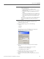
1
User Manual
SLC 500 EtherNet/IP Adapter
Catalog Number 1747-AENTR
Important User Information
Solid-state equipment has operational characteristics differing from those of electromechanical equipment. Safety
Guidelines for the Application, Installation and Maintenance of Solid State Controls (publication SGI-1.1 available from
your local Rockwell Automation sales office or online at http://www.rockwellautomation.com/literature/) describes some
important differences between solid-state equipment and hard-wired electromechanical devices. Because of this difference,
and also because of the wide variety of uses for solid-state equipment, all persons responsible for applying this equipment
must satisfy themselves that each intended application of this equipment is acceptable.
In no event will Rockwell Automation, Inc. be responsible or liable for indirect or consequential damages resulting from
the use or application of this equipment.
The examples and diagrams in this manual are included solely for illustrative purposes. Because of the many variables and
requirements associated with any particular installation, Rockwell Automation, Inc. cannot assume responsibility or
liability for actual use based on the examples and diagrams.
No patent liability is assumed by Rockwell Automation, Inc. with respect to use of information, circuits, equipment, or
software described in this manual.
Reproduction of the contents of this manual, in whole or in part, without written permission of Rockwell Automation,
Inc., is prohibited.
Throughout this manual, when necessary, we use notes to make you aware of safety considerations.
WARNING: Identifies information about practices or circumstances that can cause an explosion in a hazardous
environment, which may lead to personal injury or death, property damage, or economic loss.
ATTENTION: Identifies information about practices or circumstances that can lead to personal injury or death,
property damage, or economic loss. Attentions help you identify a hazard, avoid a hazard, and recognize the
consequence
SHOCK HAZARD: Labels may be on or inside the equipment, for example, a drive or motor, to alert people that
dangerous voltage may be present.
BURN HAZARD: Labels may be on or inside the equipment, for example, a drive or motor, to alert people that
surfaces may reach dangerous temperatures.
IMPORTANT
Identifies information that is critical for successful application and understanding of the product.
Allen-Bradley, SLC 500, RSLogix 5000, Rockwell Automation, and TechConnect are trademarks of Rockwell Automation, Inc.
Trademarks not belonging to Rockwell Automation are property of their respective companies.
Preface
Read this preface to familiarize yourself with the rest of the manual. It provides
information concerning:
• who should use this manual
• the purpose of this manual
• related documentation
Who Should Use this
Manual
Use this manual if you are responsible for designing, installing, programming, or
troubleshooting control systems that use the EtherNet/IP Adapter Module.
You should have a basic understanding of electrical circuitry and familiarity with
relay logic. If you do not, obtain the proper training before using this product.
Purpose of this Manual
This manual is a reference guide for the EtherNet/IP Adapter Module. It
describes the procedures you use to install, program and troubleshoot your
module. This manual also includes several application examples.
Additional Resources
These documents contain additional information concerning related Rockwell
Automation products
Resource
Description
Ethernet Design Considerations Reference Manual,
publication ENET-RM002
Provides design considerations such as EtherNet/IP infrastructure components,
features, protocol and prediction of system performance.
EtherNet/IP Embedded Switch Technology Application Guide,
publication ENET-AP005
Describes how to install, configure and maintain linear and Device-level Ring
(DLR) networks using Rockwell Automation EtherNet/IP devices with
embedded switch technology.
EtherNet/IP Network Configuration User Manual,
publication ENET-UM001
Describes how you can use EtherNet/IP communication modules with your
Logix5000 controller and communicate with various devices on the Ethernet
network.
EtherNet/IP Web Server Module User Manual,
publication ENET-UM527
Describes how to use the EtherNet/IP Web server module.
Industrial Automation Wiring and Grounding Guidelines,
publication 1770-4.1
Provides general guidelines for installing a Rockwell Automation industrial
system.
Product Certifications website, http://ab.com
Provides declarations of conformity, certificates, and other certification details.
Application Considerations for Solid-State Controls SGI-1.1
A description of important differences between solid-state programmable
controller products and hard-wired electromechanical devices.
National Electrical Code - Published by the National Fire
Protection Association of Boston, MA.
An article on wire sizes and types for grounding electrical equipment.
Allen-Bradley Industrial Automation Glossary AG-7.1
A glossary of industrial automation terms and abbreviations.
You can view or download publications at http://www.rockwellautomation.com/
literature/. To order paper copies of technical documentation, contact your local
Rockwell Automation distributor or sales representative.
Rockwell Automation Publication 1747-UM076C-EN-E - January 2013
iii
Preface
Notes:
iv
Rockwell Automation Publication 1747-UM076C-EN-E - January 2013
Table of Contents
Preface
Who Should Use this Manual . . . . . . . . . . . . . . . . . . . . . . . . . . . . . . . . . . . . . . iii
Purpose of this Manual . . . . . . . . . . . . . . . . . . . . . . . . . . . . . . . . . . . . . . . . . . . . iii
Additional Resources . . . . . . . . . . . . . . . . . . . . . . . . . . . . . . . . . . . . . . . . . . . . . . iii
Chapter 1
About the SLC 500 EtherNet/IP
Adapter
Overview . . . . . . . . . . . . . . . . . . . . . . . . . . . . . . . . . . . . . . . . . . . . . . . . . . . . . . . . . . 1
Module Description . . . . . . . . . . . . . . . . . . . . . . . . . . . . . . . . . . . . . . . . . . . . . . . . 1
Hardware Components. . . . . . . . . . . . . . . . . . . . . . . . . . . . . . . . . . . . . . . . . . . . . 2
The 1747-AENTR in a Logix System . . . . . . . . . . . . . . . . . . . . . . . . . . . . . . . . 3
Hardware/Software Compatibility . . . . . . . . . . . . . . . . . . . . . . . . . . . . . . . . . . 4
Diagnostic Indicators . . . . . . . . . . . . . . . . . . . . . . . . . . . . . . . . . . . . . . . . . . . . . . . 4
What the Adapter Does . . . . . . . . . . . . . . . . . . . . . . . . . . . . . . . . . . . . . . . . . . . . 5
Use of the Common Industrial Protocol (CIP) . . . . . . . . . . . . . . . . . . . . . . . 5
Understand the Producer/Consumer Model . . . . . . . . . . . . . . . . . . . . . . . . . 5
Support of Direct Connections. . . . . . . . . . . . . . . . . . . . . . . . . . . . . . . . . . . . . . 6
Chapter Summary. . . . . . . . . . . . . . . . . . . . . . . . . . . . . . . . . . . . . . . . . . . . . . . . . . 6
Chapter 2
Install Your Adapter
Set the Network Address Switches . . . . . . . . . . . . . . . . . . . . . . . . . . . . . . . . . . . 7
Determine Power Requirements. . . . . . . . . . . . . . . . . . . . . . . . . . . . . . . . . . . . . 8
Install the Adapter Module in the Chassis . . . . . . . . . . . . . . . . . . . . . . . . . . . . 8
Connect Your Adapter to the Ethernet/IP Network through RJ-45
Connection. . . . . . . . . . . . . . . . . . . . . . . . . . . . . . . . . . . . . . . . . . . . . . . . . . . . . . . . 9
Chapter Summary. . . . . . . . . . . . . . . . . . . . . . . . . . . . . . . . . . . . . . . . . . . . . . . . 11
Chapter 3
Configure the Adapter for Your
EtherNet/IP Network
Configuration Requirements . . . . . . . . . . . . . . . . . . . . . . . . . . . . . . . . . . . . . .
IP Address . . . . . . . . . . . . . . . . . . . . . . . . . . . . . . . . . . . . . . . . . . . . . . . . . . .
Gateway Address . . . . . . . . . . . . . . . . . . . . . . . . . . . . . . . . . . . . . . . . . . . . .
Subnet Mask . . . . . . . . . . . . . . . . . . . . . . . . . . . . . . . . . . . . . . . . . . . . . . . . .
Use the Rockwell Automation BootP/DHCP Utility . . . . . . . . . . . . . . .
Save the Relation List . . . . . . . . . . . . . . . . . . . . . . . . . . . . . . . . . . . . . . . . .
Use DHCP Software to Configure Your Adapter . . . . . . . . . . . . . . . . . . .
Chapter Summary. . . . . . . . . . . . . . . . . . . . . . . . . . . . . . . . . . . . . . . . . . . . . . . .
13
14
14
15
16
18
19
19
Chapter 4
Plan to Use Your EtherNet/IP
Adapter
Compatible 1746 and 1747 I/O Modules . . . . . . . . . . . . . . . . . . . . . . . . . .
Overview of Adapter Operation . . . . . . . . . . . . . . . . . . . . . . . . . . . . . . . . . . .
Software Requirements . . . . . . . . . . . . . . . . . . . . . . . . . . . . . . . . . . . . . . .
Module Connections . . . . . . . . . . . . . . . . . . . . . . . . . . . . . . . . . . . . . . . . .
Module Keying. . . . . . . . . . . . . . . . . . . . . . . . . . . . . . . . . . . . . . . . . . . . . . .
Output Operation During Fault and Idle Modes . . . . . . . . . . . . . . . .
Chapter Summary. . . . . . . . . . . . . . . . . . . . . . . . . . . . . . . . . . . . . . . . . . . . . . . .
Rockwell Automation Publication 1747-UM076C-EN-E - January 2013
21
23
24
24
25
25
25
v
Table of Contents
Chapter 5
Configure the Adapter for Direct
Connection through the
RSLogix 5000 or Logix Designer
Software
Overview . . . . . . . . . . . . . . . . . . . . . . . . . . . . . . . . . . . . . . . . . . . . . . . . . . . . . . . .
Set Up the Hardware . . . . . . . . . . . . . . . . . . . . . . . . . . . . . . . . . . . . . . . . . . . . .
Create the Example Application . . . . . . . . . . . . . . . . . . . . . . . . . . . . . . . . . . .
Configure the I/O . . . . . . . . . . . . . . . . . . . . . . . . . . . . . . . . . . . . . . . . . . . . . . . .
Add the Local EtherNet/IP Bridge to the I/O Configuration. . . . .
Add the Adapter to the I/O Configuration . . . . . . . . . . . . . . . . . . . . . . . . .
Add I/O Modules to the I/O Configuration . . . . . . . . . . . . . . . . . . . .
Add Specialty I/O Modules using Advanced Connection . . . . . . . .
Download the Program to the Controller. . . . . . . . . . . . . . . . . . . . . . . . . . .
Custom Settings
(Edit Adapter Configuration) . . . . . . . . . . . . . . . . . . . . . . . . . . . . . . . . . . . . .
Custom Settings for your
I/O Module. . . . . . . . . . . . . . . . . . . . . . . . . . . . . . . . . . . . . . . . . . . . . . . . . . . . . .
Online Monitoring . . . . . . . . . . . . . . . . . . . . . . . . . . . . . . . . . . . . . . . . . . . . . . .
Chapter Summary . . . . . . . . . . . . . . . . . . . . . . . . . . . . . . . . . . . . . . . . . . . . . . . .
27
27
28
29
30
31
33
37
42
43
46
50
51
Chapter 6
Troubleshoot with the Status
Indicators
Interpret the Indicators . . . . . . . . . . . . . . . . . . . . . . . . . . . . . . . . . . . . . . . . . . . 53
Chapter Summary . . . . . . . . . . . . . . . . . . . . . . . . . . . . . . . . . . . . . . . . . . . . . . . . 56
Appendix A
Specifications
. . . . . . . . . . . . . . . . . . . . . . . . . . . . . . . . . . . . . . . . . . . . . . . . . . . . . . . . . . . . . . . . . 57
Appendix B
Adapter Web Dialogs
Overview . . . . . . . . . . . . . . . . . . . . . . . . . . . . . . . . . . . . . . . . . . . . . . . . . . . . . . . .
Work with the Home Page . . . . . . . . . . . . . . . . . . . . . . . . . . . . . . . . . . . . . . . .
Work with the Diagnostics Pages . . . . . . . . . . . . . . . . . . . . . . . . . . . . . . . . . .
Use the Diagnostic Overview Page . . . . . . . . . . . . . . . . . . . . . . . . . . . . .
Use the Network Settings Page. . . . . . . . . . . . . . . . . . . . . . . . . . . . . . . . .
Use the Ethernet Statistics Page . . . . . . . . . . . . . . . . . . . . . . . . . . . . . . . .
Use the I/O Connections Page. . . . . . . . . . . . . . . . . . . . . . . . . . . . . . . . .
Work with the Configuration Pages. . . . . . . . . . . . . . . . . . . . . . . . . . . . . . . .
Use the Device Identity Page. . . . . . . . . . . . . . . . . . . . . . . . . . . . . . . . . . .
Use the Network Configuration Page . . . . . . . . . . . . . . . . . . . . . . . . . .
Use the Device Services Page. . . . . . . . . . . . . . . . . . . . . . . . . . . . . . . . . . .
59
59
61
61
63
64
65
66
68
68
70
Appendix C
Configure the RSLinx Ethernet
Communication Driver
Index
vi
Overview . . . . . . . . . . . . . . . . . . . . . . . . . . . . . . . . . . . . . . . . . . . . . . . . . . . . . . . .
Install the RSLinx Software . . . . . . . . . . . . . . . . . . . . . . . . . . . . . . . . . . . . . . .
Configure the AB_ETH/IP Driver . . . . . . . . . . . . . . . . . . . . . . . . . . . . . . . .
.................................................................
71
71
71
75
Rockwell Automation Publication 1747-UM076C-EN-E - January 2013
Chapter
1
About the SLC 500 EtherNet/IP Adapter
Overview
Module Description
This chapter provides an introduction to the features and functionalities of the
1747-AENTR SLC 500 EtherNet/IP Adapter. It includes the following sections.
Topic
Page
Module Description
1
Hardware Components
2
The 1747-AENTR in a Logix System
3
Hardware/Software Compatibility
4
Diagnostic Indicators
4
What the Adapter Does
5
Use of the Common Industrial Protocol (CIP)
5
Understand the Producer/Consumer Model
5
Support of Direct Connections
6
The 1747-AENTR Adapter enables CompactLogix and ControlLogix
processors to control SLC I/O modules. It is primarily designed to enable
migration of existing SLC controlled systems to Logix-based systems.
The adapter mainly acts as a gateway between the SLC backplane and
EtherNet/IP and typically replaces an SLC controller in the 1746 rack. On
remote SLC racks, it replaces the 1747-ASB module or the ControlNet adapters
1747-ACN15 and 1747-ACNR15.
Control of the backplane I/O is accomplished with a CompactLogix or
ControlLogix controller communicating through an EtherNet/IP router in the
Logix backplane, across EtherNet/IP, and into the 1747-AENTR gateway.
As a gateway between the SLC backplane and EtherNet/IP, the 1747-AENTR
module is a CIP server (for both Explicit Messaging and I/O) on the Ethernet
port, and an SLC host on the 1746 backplane.
Rockwell Automation Publication 1747-UM076C-EN-E - January 2013
1
Chapter 1
About the SLC 500 EtherNet/IP Adapter
Connections can be made to support 1746 and 1747 analog, digital, and specialty
I/O modules installed in the backplane.
IMPORTANT
Logix Designer application (previously RSLogix 5000) revision 21 and
later, and firmware revision 2.001 and later supports:
• multiple chassis, with a maximum number of three chassis;
• a maximum of 30 SLC I/O modules;
• a maximum of 96 Class 1 connections;
• up to 8 Class 3 connections.
For the complete list of supported I/O modules, see the table, List of I/O
Modules Supported by the 1747-AENTR Adapter on page 21.
Hardware Components
The adapter module consists of the following hardware components:
1747-AENTR
Network switches
5.1
4-character dot matrix display
5
LINK1 LINK2 MOD
Module status indicator
Link 2 status indicator
Latch
Link 1 status indicator
Front cover
7
1.3
5.72
PCB
Link 1
Link 2
RJ-45 Ethernet connectors
Side view
2
Front view
Rockwell Automation Publication 1747-UM076C-EN-E - January 2013
About the SLC 500 EtherNet/IP Adapter
45845
Chapter 1
45846
Right side view
Left side view
Ethernet connectors (RJ-45)
1
8
8
1
45844
Bottom view
The 1747-AENTR in a
Logix System
In this example, the I/O modules communicate with the controller through the
1747-AENTR adapter. The controller can produce and consume tags to the I/O.
Configuration of devices and the network is done through the personal computer
running the controller and configuration software.
PC running
controller and
Rockwell Automation
configuration software
EtherNet/IP Network
ControlLogix
Controller
Rockwell Automation Publication 1747-UM076C-EN-E - January 2013
PanelView
Terminal
1747-AENTR Adapter
45848
3
Chapter 1
About the SLC 500 EtherNet/IP Adapter
Hardware/Software
Compatibility
Diagnostic Indicators
4
The adapter and the applications described in this manual is compatible with the
following firmware revisions and software releases.
Product
Firmware Revision/
Software Release
1747-AENTR
1.001 or later
Logix controller
v20 or later
RSLogix 5000 or Logix Designer
v20 or later
RSLinx software
v2.59 or later
The module has the following diagnostic indicators:
• Link 1 and Link 2 status indicator
• Module indicator
• 4-character status display
Rockwell Automation Publication 1747-UM076C-EN-E - January 2013
About the SLC 500 EtherNet/IP Adapter
What the Adapter Does
Chapter 1
The 1747-AENTR EtherNet/IP adapter performs the following primary tasks:
• Control of real-time I/O data (also known as implicit messaging) – the
adapter serves as a bridge between I/O modules and the network
• Support of messaging data for configuration and programming
information (also known as explicit messaging)
CONTROLLER
E
N
B
T
EtherNet/IP Network
1
7
4
7
A
E
N
T
R
Use of the Common
Industrial Protocol (CIP)
SLC I/O
Other
Network
Devices
The adapter uses the Common Industrial Protocol (CIP), the application layer
protocol specified for EtherNet/IP, the Ethernet Industrial Protocol. It is a
message-based protocol that implements a relative path to send a message from
the producing device in a system to the consuming devices.
The producing device contains the path information that steers the message along
the proper route to reach its consumers. Since the producing device holds this
information, other devices along the path simply pass this information; they do
not store it.
This has the following significant benefits:
• You do not need to configure routing tables in the bridging modules,
which greatly simplifies maintenance and module replacement.
• You maintain full control over the route taken by each message, which
enables you to select alternative paths for the same end device.
Understand the Producer/
Consumer Model
The CIP producer and consumer networking model replaces the old source and
destination (master and slave) model. The producer and consumer model reduces
network traffic and increases speed of transmission. In traditional I/O systems,
controllers poll input modules to obtain their input status. In the CIP system,
Rockwell Automation Publication 1747-UM076C-EN-E - January 2013
5
Chapter 1
About the SLC 500 EtherNet/IP Adapter
input modules are not polled by a controller. Instead, they produce (multicast or
unicast) their data periodically or at a cyclic rate.
Unicast is the default for version 20 with multicast as a selectable option. The
frequency of update depends upon the options chosen during configuration and
where on the network the input module resides. The input module, therefore, is a
producer of input data, and the controller is a consumer of the data.
The controller also produces data for other controllers to consume. The
produced and consumed data is accessible by multiple controllers and other
devices over the EtherNet/IP network. This data exchange conforms to the
producer and consumer model.
Support of Direct
Connections
The EtherNet/IP adapter only supports direct connections. A direct connection
is a real-time data transfer link between a Logix controller and a 1746/1747 I/O
module through the 1747-AENTR adapter. Direct I/O connections occur at a
cyclic rate specified by the RPI during configuration.
The adapter can support direct connections to devices in expansion racks. This
feature is supported on Logix Designer application (previously RSLogix 5000
software) revision 21 and later, and firmware revision 2.001 and later.
See the EtherNet/IP Performance and Application Guide, publication number
ENET-AP001, for more information on connections.
Chapter Summary
6
This chapter provided an overview of the module features, what it does, and its
function in a Logix system.
Rockwell Automation Publication 1747-UM076C-EN-E - January 2013
Chapter
2
Install Your Adapter
This chapter describes how to install the 1747-AENTR adapter and connect it to
the EtherNet/IP network.
The following table lists where to find specific information.
Topic
Set the Network Address
Switches
Page
Set the Network Address Switches
7
Determine Power Requirements
8
Install the Adapter Module in the Chassis
8
Connect Your Adapter to the Ethernet/IP Network through RJ-45 Connection
9
Chapter Summary
11
The network address switches are set to 999 and DHCP enabled, by default. You
can set the network Internet Protocol (IP) address in the following ways:
• Use the network address switches on the module.
• Use a Dynamic Host Configuration Protocol (DHCP) server, such as
Rockwell Automation BootP/DHCP.
• Retrieve the IP address from nonvolatile memory.
The adapter reads the network address switches first to determine if the switches
are set to a valid number. You set the node address by using the network address
switches. Valid settings range from 001…254.
When the switches are set to a valid number, the adapter’s IP address is
192.168.1.xxx (where xxx represents the number set on the switches).
Rockwell Automation Publication 1747-UM076C-EN-E - January 2013
7
Chapter 2
Install Your Adapter
The adapter’s subnet mask is 255.255.255.0 and the gateway address is set to
0.0.0.0. The adapter does not have a host name assigned, or use any Domain
Name System when using the network address switch settings.
If the switches are set to an invalid number (for example, 000 or a value greater
than 254 excluding 888), the adapter checks to see if DHCP is enabled. Setting
the switches to 888 restores default factory settings.
IMPORTANT
If you set the value of the adapter switch to 888 and then power cycle the
module, the following occurs:
• The DHCP Enabled function is enabled (set to True).
• The Ethernet link is negotiated automatically. The Auto Negotiate function is
set to True.
• The web server is enabled. The Disabled Web Server function is disabled.
• The Ethernet ports are disabled. Both ports are re-enabled once the
switches are returned to their previous value and power is cycled.
DHCP Enabled and Not Enabled
DHCP Enabled and Not Enabled
If DHCP is
Then the Adapter
Enabled
Asks for an address from a DHCP server. The DHCP server also assigns other
Transport Control Protocol (TCP) parameters.
The 1747-AENTR factory default is DHCP enabled. When you apply power, the
module sends a message containing its hardware address to any DHCP server on
the network. The server(s) replies by sending a message with an appropriate IP
address for the adapter. The adapter responds by acknowledging to a server that
it will use the offered IP address.
Not enabled
Uses the IP address (along with other TCP configurable parameters) stored in
nonvolatile memory.
When the IP address assigned to the module, as indicated in the four-character
dot matrix status display, is changed through the DHCP configuration utility, the
DHCP is disabled.
When power is cycled to the device, it uses the new configuration and
implements the new IP address.
See the chapter, Configure the Adapter for Your EtherNet/IP Network on page
13, for information on how to use your BootP/DHCP utility to configure your
adapter for the network.
Determine Power
Requirements
The Ethernet adapter requires 5V DC with current consumption of 470 mA.
The power is supplied through backplane from SLC power supply. Remember to
consider this requirement when planning your system configuration.
Install the Adapter Module
in the Chassis
After you set the appropriate switch assemblies for your adapter module, follow
these procedures for installation.
8
Rockwell Automation Publication 1747-UM076C-EN-E - January 2013
Install Your Adapter
Chapter 2
Refer to the Industrial Controller Wiring and Grounding Guidelines publication
1770-4.1 for proper grounding and wiring methods to use when installing your
module.
1. Remove power from the I/O chassis before inserting (or removing) the
module.
2. Align the circuit board with the chassis card guide in the left slot.
3. Install the module in slot 0 of the chassis by aligning the circuit board with
the chassis card guide.
The 1747-AENTR module must be installed only in slot 0 (leftmost
slot)of the chassis.
4. Press firmly and evenly to seat the module in its backplane connectors. To
remove the module, press the releases at the top and bottom of the module
and pull it out.
ATTENTION: Do not force the module into the backplane connector. If
you cannot seat the module with firm pressure, check the alignment.
Forcing the module can damage the backplane connector or the module.
Connect Your Adapter to the
Ethernet/IP Network
through RJ-45 Connection
Connect your 1747-AENTR adapter module to an Ethernet/IP network as
shown below:
Rockwell Automation Publication 1747-UM076C-EN-E - January 2013
9
Chapter 2
Install Your Adapter
Wire the RJ-45 connectors as shown.
Signal
1
TxData+
2
TxData-
3
Recv Data+
4
Reserved
5
Reserved
6
Recv Data-
7
Reserved
8
Reserved
RJ-45
RJ-45 connectors
1
8
8
1
45844
1747-AENTR module bottom view
To connect the module to the network, follow these steps:
WARNING: If you connect or disconnect the communication cable with
power applied to this module or any device on the network, an electrical
arc can occur. This could cause an explosion in hazardous location
installations. Be sure that power is removed or the area is nonhazardous
before proceeding.
1. Attach the cables with the RJ-45 connectors to the two Ethernet ports on
the bottom of the module.
2. Attach the other end of the cables to the devices in your network.
IMPORTANT
10
To install systems with rack extensions, you can refer to the SLC 500 Modular
Hardware Style User Manual, publication 1747-UM011.
Rockwell Automation Publication 1747-UM076C-EN-E - January 2013
Install Your Adapter
Chapter Summary
Chapter 2
This chapter provided instructions on how to install and wire the module. It also
included power requirements for the module.
Rockwell Automation Publication 1747-UM076C-EN-E - January 2013
11
Chapter 2
Install Your Adapter
Notes:
12
Rockwell Automation Publication 1747-UM076C-EN-E - January 2013
Chapter
3
Configure the Adapter for Your
EtherNet/IP Network
Before using your adapter in an EtherNet/IP network, you need to configure it
with an IP address, subnet mask, and optional Gateway address. This chapter
describes these configuration requirements and the procedures for providing
them. Here are ways you can do this:
• Use the Rockwell Automation BootP/DHCP utility, version 2.3 or later,
that ships with RSLogix 5000 or RSLinx software.
– You can also use this utility to reconfigure a device with an IP address
you must change.
• Use a third party DHCP server.
• Use the Network Address rotary switches.
• Have your network administrator configure the adapter via the network
DHCP server.
See the table for a list of where to find information in this chapter.
Configuration
Requirements
Topic
Page
Configuration Requirements
13
Use the Rockwell Automation BootP/DHCP Utility
16
Use DHCP Software to Configure Your Adapter
19
Before you can use your adapter, you must configure its IP address, its subnet
mask, and, optionally, a gateway address. You can use the Rockwell Automation
BootP utility, version 2.3 or later, to perform the configuration. You can also use a
DHCP server or the network address switches to configure these parameters.
If you need to reset the adapter to factory defaults, see Work with the
Configuration Pages on page 66.
Rockwell Automation Publication 1747-UM076C-EN-E - January 2013
13
Chapter 3
Configure the Adapter for Your EtherNet/IP Network
IP Address
The IP address identifies each node on the IP network, or system of connected
networks. Each TCP/IP node on a network, including the adapter, must have a
unique IP address.
The IP address is 32 bits long and has a Network ID part and Host ID part.
Networks are classified A, B, C, or other. The class of the network determines
how an IP address is formatted.
7 8
Class A
0
0
Class B
0
10
Class C
0
110
31
Network ID
Host ID
31
15 16
Network ID
Host ID
23 24
Network ID
31
Host ID
You can distinguish the class of the IP address from the first integer in its dotteddecimal IP address as follows:
Range of first
integer
Class
Range of first
integer
Class
0 1…27
A
192…223
C
128…191
B
224… 255
Other
Each node on the same physical network must have an IP address of the same
class and must have the same network ID. Each node on the same network must
have a different Host ID thus giving it a unique IP address.
IP addresses are written as four decimal integers (0…255) separated by periods
where each integer gives the value of one byte of the IP address.
EXAMPLE
For example, the 32-bit IP address:
10000000 00000001 00000000 00000001 is written as 128.1.0.1
Gateway Address
This section applies to multi-network systems. If you have a single network
system, refer to the next section.
The Gateway Address is the default address of a network. It provides a single
domain name and point of entry to the site. Gateways connect individual physical
networks into a system of networks.
14
Rockwell Automation Publication 1747-UM076C-EN-E - January 2013
Configure the Adapter for Your EtherNet/IP Network
Chapter 3
When a node needs to communicate with a node on another network, a gateway
transfers the data between the two networks. The figure shows gateway G
connecting Network 1 with Network 2.
A
128.1.0.1
128.1.0.2
Network 1
G
B
C
128.2.0.1
128.2.0.2
128.2.0.3
Network 2
When host B with IP address 128.2.0.1 communicates with host C, it knows
from C’s IP address that C is on the same network. In an Ethernet environment,
B can then resolve C’s IP address into a hardware address (MAC address) and
communicate with C directly.
When host B communicates with host A, it knows from A’s IP address that A is
on another network (the network IDs are different). In order to send data to A, B
must use the IP address of the gateway connecting the two networks. In this
example, the gateway’s IP address on Network 2 is 128.2.0.3.
The gateway has two IP addresses (128.1.0.2 and 128.2.0.3). The first must be
used by hosts on Network 1 and the second must be used by hosts on Network 2.
To be usable, a gateway of a host must be addressed using a network ID matching
its own.
Subnet Mask
The subnet mask is used for splitting IP networks into a series of subgroups, or
subnets. The mask is a binary pattern that is matched up with the IP address to
turn part of the Host ID address field into a field for subnets.
EXAMPLE
Take Network 2 (a Class B network) in the previous example and add
another physical network. Selecting the following subnet mask would
add two additional network ID bits, allowing for four physical networks:
11111111 11111111 11000000 00000000 = 255.255.192.0
These two bits of the Host ID are used to
extend the netdwork ID.
Rockwell Automation Publication 1747-UM076C-EN-E - January 2013
15
Chapter 3
Configure the Adapter for Your EtherNet/IP Network
Two bits of the Class B host ID are used to extend the network ID. Each unique
combination of bits in the part of the Host ID where subnet mask bits are 1
specifies a different physical network.
The new configuration is:
A
128.1.0.1
Network 1
128.1.0.2
G
B
C
128.2.64.1
128.2.64.3
128.2.64.2
Network 2.1
G2
D
E
128.2.128.1
128.2.128.3
128.2.128.2
Network 2.2
A second network with Hosts D and E was added. Gateway G2 connects
Network 2.1 with Network 2.2.
Hosts D and E will use Gateway G2 to communicate with hosts not on
Network 2.2.
Hosts B and C will use Gateway G to communicate with hosts not on
Network 2.1.
When B is communicating with D, G (the configured Gateway for B) will route
the data from B to D through G2.
Use the
Rockwell Automation
BootP/DHCP Utility
The Rockwell Automation BootP/DHCP utility is a standalone program that
incorporates the functionality of standard BootP software with a user friendly
graphical interface. It is located in the Utility directory on the RSLogix 5000
software installation CD. The adapter must have DHCP enabled (factory default
and the network address switches set to an invalid value) to use the utility.
To configure your adapter using the BootP utility, perform the following steps:
16
Rockwell Automation Publication 1747-UM076C-EN-E - January 2013
Configure the Adapter for Your EtherNet/IP Network
Chapter 3
1. Run the BootP software.
In the BOOTP Request History panel you see the hardware addresses of
devices issuing BootP requests.
2. Double-click the hardware address of the device you want to configure.
The New Entry dialog appears with the device’s Ethernet Address (MAC).
3. Enter the IP Address you want to assign to the device and click OK. The
device is added to the Relation List, displaying the Ethernet Address
(MAC) and corresponding IP Address, Hostname, and Description (if
applicable).
Rockwell Automation Publication 1747-UM076C-EN-E - January 2013
17
Chapter 3
Configure the Adapter for Your EtherNet/IP Network
When the address displays in the IP Address column in the Request
History section, the IP address assignment has been made.
4. To make this configuration static in the device, highlight the device in the
Relation List panel, and click the Disable BOOTP/DHCP button.
When power is cycled to the device, it uses the configuration saved in nonvolatile memory and will not issue a DHCP request.
5. To enable DHCP for a device with DHCP disabled, highlight the device
in the Relation List, and click the Enable DHCP button.
You must have an entry for the device in the Relation List panel to reenable DHCP.
Save the Relation List
You can save the Relation List for later use. To save the Relation List, perform the
following steps:
1. Select Save As... from the File menu.
The Save As dialog appears.
18
Rockwell Automation Publication 1747-UM076C-EN-E - January 2013
Configure the Adapter for Your EtherNet/IP Network
Chapter 3
2. Select the folder where you want to save the Relation List.
3. Enter a File name for the Relation List, for example, control system
configuration, and click Save.
You can leave the Save as type at the default setting: Bootp Config Files
(*.bpc).
You now have the option to open the file containing the Relation List at a
later session.
Use DHCP Software to
Configure Your Adapter
DHCP (Dynamic Host Configuration Protocol) software automatically assigns
IP addresses to client stations logging onto a TCP/IP network.
DHCP is based on BootP and maintains some backward compatibility. The main
difference is that BootP was designed for manual configuration, while DHCP
allows for dynamic allocation of network addresses and configurations to newly
attached devices.
Be cautious about using DHCP software to configure your adapter. A DHCP
server typically assigns a finite lease time to the offered IP address.
When 50% of the leased time has expired, the adapter attempts to renew its IP
address with the DHCP server.
The possibility exists that the adapter will be assigned a different IP address,
which would cause the adapter to cease communicating with the ControlLogix
controller.
See Configure the Adapter with Fixed IP Address on page 45 to configure the
adapter with a fixed IP address.
ATTENTION: To avoid unintended control or loss of control, the I/O
adapter must be assigned a fixed IP address. A dynamically provided IP
address should be used only at initial configuration. If a DHCP server is
used, it must be configured to assign the same IP address to your adapter.
Failure to observe this precaution may result in unintended machine
motion or loss of process control.
Chapter Summary
This chapter described the requirements and procedures for configuring the IP
address, subnet mask, and optional Gateway address.
Rockwell Automation Publication 1747-UM076C-EN-E - January 2013
19
Chapter 3
Configure the Adapter for Your EtherNet/IP Network
Notes:
20
Rockwell Automation Publication 1747-UM076C-EN-E - January 2013
Chapter
4
Plan to Use Your EtherNet/IP Adapter
This chapter explains how the adapter operates on Ethernet and provides
information to assist you in configuring your system. This includes
information on:
• compatible 1746 and 1747 modules
• overview of adapter operation
• software requirements
• module connections
• module keying
• output operation during Fault and Idle modes
Compatible 1746 and
1747 I/O Modules
The majority of 1746 and 1747 discrete, analog and specialty modules are
compatible with the 1747-AENTR adapter.
The following tables provide lists of supported and unsupported modules.
List of I/O Modules Supported by the 1747-AENTR Adapter
Catalog
Number
Type
Catalog
Number
Type
1746-IA4
AC Digital Input Module
1746-OG16
DC Digital Output Module
1746-IA8
AC Digital Input Module
1746-OV8
DC Digital Output Module
1746-IA16
AC Digital Input Module
1746-OV16
DC Digital Output Module
1746-IB8
DC Digital Input Module
1746-OV32
DC Output Module
1746-IB16
DC Digital Input Module
1746-OVP16
DC Digital Output Module
1746-IB32
DC Input Module
1746-OW4
AC/DC Relay Output Module
1746-IC16
DC Digital Input Module
1746-OW8
AC/DC Relay Output Module
1746-IG16
DC Digital Input Module
1746-OW16
AC/DC Relay Output Module
1746-IH16
DC Digital Input Module
1746-OX8
AC/DC Relay Output Module
1746-IM4
AC Digital Input Module
1746-FIO4I
Analog Combination Module
1746-IM8
AC Digital Input Module
1746-FIO4V
Analog Combination Module
1746-IM16
AC Digital Input Module
1746-INT4
Thermocouple Isolated Input
Module
1746-IN16
AC/DC Digital Input Module
1746-NI4
Analog Input Module
1746-IO4
Digital Combination Module
1746-NI8(1)
Analog Input Module
1746-IO8
Digital Combination Module
1746-NIO4I
Analog Combination Module
1746-IO12
Digital Combination Module
1746-NIO4V
Analog Combination Module
Rockwell Automation Publication 1747-UM076C-EN-E - January 2013
21
Chapter 4
Plan to Use Your EtherNet/IP Adapter
List of I/O Modules Supported by the 1747-AENTR Adapter
Catalog
Number
Catalog
Number
Type
1746-IO12DC Digital Combination Module
1746-NO4I
Analog Output Module
1746-ITB16
DC Digital Input Module
1746-NO4V
Analog Output Module
1746-ITV16
DC Digital Input Module
1746-NR4
RTD/Resistance Input Module
1746-IV8
DC Digital Input Module
1746-NT4
Thermocouple/mV Input Module
DC Digital Input Module
1746-NI16V(1)
Analog Input Module
DC Digital Input Module
1746-NI16I(1)
Analog Input Module
1746-OA8
AC Digital Output Module
1746-NR8(1)
RTD/Resistance Input Module
1746-OA16
AC Digital Output Module
1746-NT8
Thermocouple/mV Input Module
AC Digital Output Module
1746-NO8I(1)
Analog Output Module
1746-OB6EI
DC Digital Output Module
1746-NO8V(1)
Analog Output Module
1746-OB8
DC Digital Output Module
1746-HSTP1
Stepper Controller Module
DC Digital Output Module
1746-HSCE(2)
High-Speed Counter Module
1746-OB16E
DC Digital Output Module
1746-HSCE2(1)
Multi-Channel High-Speed
Counter Module
1746-OB32
DC Digital Output Module
1746-QS(2)
Synchronized Axes Control
Module
1746-OB32E
DC Digital Output Module
1746-OBP16
DC Digital Output Module
1746-OBP8
DC Digital Output Module
1746-IV16
1746-IV32
1746-OAP12
1746-OB16
Type
(1) This module supports multiple operating classes. The 1747-AENTR adapter automatically promotes multiclass
modules to the highest supported class. The 1746-NI16I, 1746-NI16V, 1746-NR8, 1746-NI8, 1746-NO8I, 1746NO8V modules are promoted from class 1 to class 3. The 1746-HSCE2 module is promoted from class 1 to
class 4.
(2) This specialty module uses Advanced module connection. Refer to the User Manual specific to the I/O module
to learn about its connection configuration requirements.
List of I/O Modules NOT Supported by the 1747-AENTR Adapter
Catalog Number
Type
1746-HSRV
Servo Control Module
1746-BTM(1)
Barrel Temperature Module
1747-DCM1(1)
Direct Communication Modules
1747-DCM2(1)
1747-DCM3(1)
1747-DCM4(1)
1747-KE/A(1)
DH-485/RS-232C Interface Modules
1747-KE/B(1)
22
1747-KFC15
ControlNet to RS-232C Interface Module
1747-SDN/D(1)
DeviceNet Scanner module
1747-SCNR(1)
ControlNet Scanner module
1747-SN
Remote I/O Scanner Module
Rockwell Automation Publication 1747-UM076C-EN-E - January 2013
Plan to Use Your EtherNet/IP Adapter
Chapter 4
List of I/O Modules NOT Supported by the 1747-AENTR Adapter
Catalog Number
1747-BSN
(2)
Type
Back-Up Remote I/O Scanner Module
1746-QV
Open Loop Velocity Control Module
1746-BLM
Blow Molding Module
1746-MPM
Mold Pressure Module
1203-SM1(1)
Scanport Module (Class 4 operation)
(1) The module is not supported by the 1747-AENTR but appears in the
RSLogix 5000 pick list (Select Module Type dialog).
(2) The 1747-AENTR is not designed for redundancy support.
IMPORTANT
Any 1746/1747 module that is not included in the lists of supported and
unsupported modules is not supported by the 1747-AENTR, as of the
date of writing of this User Manual.
Consult the manufacturer of any third party module to determine if the
module is supported by the 1747-AENTR adapter.
Overview of Adapter
Operation
As a gateway between the SLC backplane and EtherNet/IP, the 1747-AENTR
module serves as a CIP server (for both Explicit Messaging and I/O) on the
Ethernet port, and an SLC host on the 1746 backplane. Connections can be
made to supported I/O modules installed in the backplane. See List of I/O
Modules Supported by the 1747-AENTR Adapter, on page 21.
The module employs the Rockwell Automation Embedded Switch Toolkit. This
implementation is an IEEE 802.3 standard compliant, Layer 2 switch that is
compatible with the IEEE 802.1 ID standard. It has three ports: two are external
ports that function as physical ports of the product and one is an internal port
that connects to the host CPU. Each of the three ports has an IEEE 802.3
compliant MAC and the ports are interconnected with each other through full
wire speed, non-blocking switching logic. The Embedded Switch Toolkit
provides support for the EtherNet/IP DLR protocol.
The adapter only supports direct connection to individual modules. Up to 96
connections per adapter are possible with a maximum of 240 words supported
per connection on firmware revision 2.001 and Logix Designer application
revision 21. The input data attributes correspond directly to the read area of the
I/O module’s data table image. The output attributes correspond directly to the
write area of the I/O module’s data table image.
IMPORTANT
Rockwell Automation Publication 1747-UM076C-EN-E - January 2013
On firmware revision 1.001 and RSLogix 5000 revision 20, the adapter
only supports up to 32 connections per adapter, with a maximum of 240
words supported per connection.
23
Chapter 4
Plan to Use Your EtherNet/IP Adapter
Communication between the 1747-AENTR module and the I/O modules is
polled, similar to an SLC controller scan cycle. The adapter maintains a list of the
module ID for each slot, and handles electronic key validation during connection
requests, while processing ForwardOpen requests to the Connection Manager.
Software Requirements
RSLogix 5000 revision 20 or greater and RSLinx version 2.59 or greater are
required to configure the 1747-AENTR adapter. For more information on how
to configure your device, see Configure the Adapter for Direct Connection
through the RSLogix 5000 or Logix Designer Application on page 27.
IMPORTANT
Logix Designer application (previously RSLogix 5000) revision 21 and
later supports direct connections to more than 13 slots.
Module Connections
The 1747-AENTR adapter supports module connections.
Module connection is performed in a deterministic and repeatable manner. This
connection allows a memory and Ethernet bandwidth efficient way to connect to
individual modules.
Each connection can be configured with the following connection types:
1. Exclusive Owner – specifies an independent connection where a single
device controls the output states in the target device. If you have an existing
Exclusive Owner connection to a target device, you cannot specify another
Exclusive Owner or Redundant connection to that same target device.
The 1747-AENTR adapter supports one Exclusive Owner connection per
SLC module.
2. Input Only – specifies an independent connection where a device receives
inputs from the target device and sends configuration data to the target
device. An Input Only connection does not send outputs; it only receives
inputs. You can specify multiple Input Only connections to the target
device from different originators.
The 1747-AENTR adapter supports up to five Input Only connections
per SLC module.
Listen Only – specifies a dependent connection where a device receives
inputs from the target device, but does not send configuration data with
the target device. A Listen Only connection only functions properly when
another non-Listen Only connection exists to the same target device. A
Listen Only connection does not send outputs; it only receives inputs. You
can specify multiple Listen Only connections to the target device from
24
Rockwell Automation Publication 1747-UM076C-EN-E - January 2013
Plan to Use Your EtherNet/IP Adapter
Chapter 4
different originators.
The 1747-AENTR adapter supports up to five Listen Only connections
per SLC module.
IMPORTANT
When a Listen Only connection is made, there must be an existing
Exclusive Owner or Input Only connection, the connection RPIs must
match exactly, the input chunk configuration (if any) must match exactly,
and all connections to the same module must be Multicast.
Note that changing a module connection from Input Only to Listen Only
will result to the following:
• reset the RPI to 20 ms
• reset the input chunk configuration (if any) to the default
• set the Input Type to Unicast
TIP
All Listen Only connections are terminated when all associated
independent connections are terminated.
Module Keying
Missing or misplaced modules are detected if the module in question is
configured with RSLogix 5000 or Logix Designer application as an individual
module connection and “compatible module” is selected for electronic keying. If
a module connection is attempted to a module which is a missing or misplaced
module, the connection will fail.
Output Operation During Fault and Idle Modes
RSLogix 5000 or Logix Designer application allows configuration to characterize
each module connection activity during certain operational states.
During idle mode and fault modes, outputs are configured for one of the
following operation states:
Output Action
Reset outputs to off
Hold last state
Write Safe State data to outputs
For comprehensive information about Ethernet/IP networks, consult the
following resources:
• Ethernet Design Considerations Reference Manual,
publication ENET-RM002
• EtherNet/IP Network Configuration User Manual, publication
ENET-UM001
Rockwell Automation Publication 1747-UM076C-EN-E - January 2013
25
Chapter 4
Plan to Use Your EtherNet/IP Adapter
Chapter Summary
26
This chapter provided an overview of adapter operation on an EtherNet/IP
network that can assist you in configuring your system.
Rockwell Automation Publication 1747-UM076C-EN-E - January 2013
Chapter
5
Configure the Adapter for Direct Connection
through the RSLogix 5000 or Logix Designer
Application
Overview
In the following example, a ControlLogix controller communicates with I/O
modules through the adapter using a direct connection.
The adapter makes a direct connection to each of the modules referenced by the
data. The modules presented in this chapter use RSLogix 5000/Logix Designer
application, revision 20 or later.
Topic
Page
Set Up the Hardware
27
Create the Example Application
28
Configure the I/O
29
Add the Local EtherNet/IP Bridge to the I/O Configuration
30
Add the Adapter to the I/O Configuration
31
Add I/O Modules to the I/O Configuration
33
Download the Program to the Controller
42
Custom Settings (Edit Adapter Configuration)
43
Custom Settings for your I/O Module
46
IMPORTANT
The steps and screenshots used in this chapter refer to the
RSLogix 5000 software, which has since been renamed to
Logix Designer application.
The configuration process in the Logix Designer application follows
the same steps as the configuration process in RSLogix 5000.
IMPORTANT
Set Up the Hardware
The 1747-AENTR device should always be installed in Slot 0. There
should only be one 1747-AENTR device installed within the same
rack or its connected rack extensions for multiple chassis support.
In this example, a ControlLogix chassis contains the Logix5575 controller in slot
1 and a 1756-EN2TR bridge module in slot 3. The 1747-AENTR adapter is
mounted on an SLC chassis in slot 0, with a 1746-IO8 input module in slot 1, a
1746-IA4 module in slot 2, a 1746-BAS/B module in slot 3, and a power supply.
Rockwell Automation Publication 1747-UM076C-EN-E - January 2013
27
28 Configure the Adapter for Direct Connection through the RSLogix 5000 or Logix Designer Application
To work along with this example, set up your system as shown in the figure.
1747-AENTR
10.88.70.2
Slot 0 1 2 3
Local
chassis
Data
Slot
Logix5575
controller (slot 1)
1746-BAS/B
0 1 2 3
1746-IA4
1756-EN2TR
10.88.70.4 (slot 3)
1746-IO8
Switch
10.88.70.26
Programming
terminal
45176
• In the example application, we assume that the Logix5575 controller and
1756-EN2TR module (firmware revision 3.1, or later) are in the slots
shown in the figure.
• Verify the IP addresses for your programming terminal, 1756-EN2TR
module, and adapter.
• Verify the position (slot) of the I/O modules on the DIN rail.
• Verify that you connected all wiring and cabling properly.
• Be sure you configured your communication driver (for example,
AB_ETH-1 or AB-ETHIP-1) in RSLinx software, as described in the
Appendix on page 71 of this manual.
Create the Example
Application
28
Perform the following steps to create the example application:
1. Start RSLogix 5000 Enterprise Series software to open the RSLogix 5000
software main dialog.
Rockwell Automation Publication 1747-UM076C-EN-E - January 2013
Configure the Adapter for Direct Connection through the RSLogix 5000 or Logix Designer Application 29
2. From the File menu, select New.
3. The New Controller dialog opens.
• Enter an appropriate Name for the Controller.
• Select the correct Chassis Type, and Slot number of the Logix5575
controller, and the folder where you want to save the RSLogix 5000 file
(Create In). The Description is optional.
4. Click OK.
Configure the I/O
Setting up a sample I/O Configuration project involves the following:
• Adding the local 1756-EN2TR module to the I/O configuration.
• Adding the 1747-AENTR adapter as a child of the 1756-EN2TR module
on the Ethernet network.
Rockwell Automation Publication 1747-UM076C-EN-E - January 2013
29
30 Configure the Adapter for Direct Connection through the RSLogix 5000 or Logix Designer Application
• Adding I/O modules as children of the 1747-AENTR adapter..
IMPORTANT
Click the Help button on the configuration dialogs shown in this
section if you need assistance in selecting and setting the
parameters.
Add the Local EtherNet/IP Bridge to the I/O Configuration
1. Right-click the I/O Configuration folder in the project dialog, and choose
New Module from the dropdown list.
The Select Module Type dialog opens.
2. Select the 1756-EN2TR EtherNet/IP Bridge and click Create.
30
Rockwell Automation Publication 1747-UM076C-EN-E - January 2013
Configure the Adapter for Direct Connection through the RSLogix 5000 or Logix Designer Application 31
3. The New Module dialog opens. Configure your 1756-EN2TR
EtherNet/IP Bridge module. You can configure the bridge module
through the different tabs available.
4. Enter values for Name, IP Address, Slot, Electronic Keying, and Revision,
noting that we used the following values:
Name
IP Address
Slot
Electronic Keying
Revision
EN2TR
10.88.70.4
3
Compatible Module
3.1
5. Click OK to accept the configuration.
Add the Adapter to the I/O
Configuration
Next, you must add the 1747-AENTR adapter as a child of the local
1756-EN2TR module.
1. In the Project dialog, right-click the local 1756-EN2TR module under the
I/O Configuration folder, and select New Module.
Rockwell Automation Publication 1747-UM076C-EN-E - January 2013
31
32 Configure the Adapter for Direct Connection through the RSLogix 5000 or Logix Designer Application
The Select Module Type dialog opens.
2. Choose 1747-AENTR. Click Create.
3. The Module Properties dialog opens. Specify the properties of the adapter.
Note that for the purposes of illustration we have specified the following
properties in the General tab of the New Module dialog.
Name
IP Address
Slot
32
TEST_1747AENTR
10.88.70.2
0
Rockwell Automation Publication 1747-UM076C-EN-E - January 2013
Configure the Adapter for Direct Connection through the RSLogix 5000 or Logix Designer Application 33
The Slot field appears grey because the slot is automatically 0 for
the 1747-AENTR adapter.
IMPORTANT
4. Click Change...
The Module Definition dialog opens.
5. Choose values for Chassis Size, Electronic Keying and Revision, noting
that we used the following values for our example:
Connection
Chassis Size
Electronic Keying
Revision
IMPORTANT
None (only choice available)
4
Compatible Module
1.1
The chassis size value equals 1 (for the adapter) plus the number of
I/O modules installed or physically present on the I/O backplane.
Connection is None by default because we are only making direct
connections.
6. Click OK to accept the configuration.
The name of your adapter appears under the Ethernet folder.
Add I/O Modules to the I/O Configuration
First, check the List of I/O Modules Supported by the 1747-AENTR Adapter on
page 21, to see if your I/O module is supported by the adapter.
Then, add the I/O module to the I/O Configuration List under the adapter.
Rockwell Automation Publication 1747-UM076C-EN-E - January 2013
33
34 Configure the Adapter for Direct Connection through the RSLogix 5000 or Logix Designer Application
In this example, you add a 1746-IO8 and a 1746-IA4 module with standard
configurations. Use these steps as a guide when configuring different I/O
modules for your system.
TIP
This example application uses I/O module default configurations.
For more information, refer to the SLC 500 Systems Selection
Guide, publication 1747-SG001.
1. Right-click the name of the 1747-AENTR adapter under the
I/O Configuration folder and select New Module.
The Select Module Type dialog opens.
2. Select the 1746-IO8 module from the list and click Create.
34
Rockwell Automation Publication 1747-UM076C-EN-E - January 2013
Configure the Adapter for Direct Connection through the RSLogix 5000 or Logix Designer Application 35
The New Module dialog opens.
3. Enter values for Name and Slot, noting that we used the following values.
Name
Slot
TEST_1746IO8
1
4. Select the Connection tab.
The RPI is selectable since it is a direct connection.
Rockwell Automation Publication 1747-UM076C-EN-E - January 2013
35
36 Configure the Adapter for Direct Connection through the RSLogix 5000 or Logix Designer Application
5. Enter 50 for requested packet interval (RPI) to set how often you exchange
data with the I/O adapter.
IMPORTANT
TIP
The default RPI of 20 ms is suitable for typical applications.
Rockwell Automation recommends that you check or enable the option
“Major Fault On Controller If Connection Fails While in Run Mode” on
both the 1747-AENTR device and supported 1746 I/O modules.
6. Click OK to save the configuration.
The module now appears under the I/O Configuration tree.
36
Rockwell Automation Publication 1747-UM076C-EN-E - January 2013
Configure the Adapter for Direct Connection through the RSLogix 5000 or Logix Designer Application 37
To add 1746-IA4 module to the project, follow the same procedure.
After adding 1746-IA4, the I/O Configuration tree should appear as follows:
Add Specialty I/O Modules using Advanced Connection
The previous example illustrates how to add I/O modules that use Simple
connection. This section shows how to add and configure a specialty I/O module
with Advanced connection (in this example, 1746-BAS/B).
IMPORTANT
Consult the User Manual and related documentation for your I/O module
to help you specify required values during configuration. User Manuals
and other related publications for 1746/1747 modules are available in
the Rockwell Automation Literature Library:
http://rockwellautomation.com/literature
For the 1746-BAS/B module, for example, you can refer to the following
publications to get module-specific configuration information:
•Publication 1746-UM004, SLC 500 BASIC and BASIC-T Modules
User Manual
•Publication 1746-RM001, BASIC Language Reference Manual
Follow these steps to add and configure your 1746-BAS/B module.
1. In the I/O Configuration tree, right-click SLC Chassis or 1747-AENTR
and choose New Module...
2. On the Select Module Type dialog that appears, select 1746-BAS/B and
click Create.
Rockwell Automation Publication 1747-UM076C-EN-E - January 2013
37
38 Configure the Adapter for Direct Connection through the RSLogix 5000 or Logix Designer Application
3. Enter a name for the device.
Note that the following values are used in this example.
Field
Value
Name
TEST_1746BASB
Revision
2.1
Electronic Keying
Compatible Module (default)
Connections
Exclusive Owner – Advanced (default)
4. Click Change... on the General tab.
On the Module Definition screen, configure data type as INT,
Input Size = 72 (INTs), Output Size = 72 (INTs). The Input Size should
match the total size of all three Input Chunks. The Output Size should
38
Rockwell Automation Publication 1747-UM076C-EN-E - January 2013
Configure the Adapter for Direct Connection through the RSLogix 5000 or Logix Designer Application 39
match the total size of all three Output Chunks. If the I/O sizes are larger
than the chunk totals, the adapter will reject the connection request. If the
chunk totals are larger than the I/O sizes, the adapter will accept the
connection (but the backplane scan may waste cycles reading input data
that will never be used).
5. Click OK on the Module Definition screen. Then, click Yes on the
RSLogix 5000 change confirmation screen that appears.
6. Click Connection tab. Enter 50 for requested packet interval (RPI) to set
how often you exchange data with the I/O adapter.
Note that Connection is set as Exclusive Owner - Advanced by default.
IMPORTANT
TIP
Rockwell Automation Publication 1747-UM076C-EN-E - January 2013
The default RPI of 20 ms is suitable for typical applications.
Rockwell Automation recommends that you check or enable the option
“Major Fault On Controller If Connection Fails While in Run Mode” on
both the 1747-AENTR device and supported 1746 I/O modules.
39
40 Configure the Adapter for Direct Connection through the RSLogix 5000 or Logix Designer Application
7. Click Configuration tab.
The Chunk configuration determines the 1747-AENTR SLC backplane
scan. Set up the chunks as follows:
• Output Chunk 1
– Size = 8 (number of Output INTs to scan)
– File = Output File
– Offset = 0 (starting INT offset in Output File)
•
–
–
–
Output Chunk 2
Size = 64 (number of M0 INTs to scan)
File = M0 File
Offset = 0 (starting INT offset in M0 File)
•
–
–
–
Output Chunk 3
Size = 0
File = <Don’t Care>
Offset = 0
•
–
–
–
Input Chunk 1
Size = 8 (number of Input INTs to scan)
File = Input File
Offset = 0 (starting INT offset in Input File)
• Input Chunk 2
– Size = 64 (number of M1 INTs to scan)
– File = M1
40
Rockwell Automation Publication 1747-UM076C-EN-E - January 2013
Configure the Adapter for Direct Connection through the RSLogix 5000 or Logix Designer Application 41
– Offset = 0 (starting INT offset in M1 File)
•
–
–
–
Input Chunk 3
Size = 0
File = <Don’t Care>
Offset = 0
8. Click OK to save the configuration.
9. On the Controller Organizer window, right-click Controller Tags under
the Controller <name> folder. Select Monitor Tags.
10. Examine the tags created for 1746-BAS/B.
• TEST_1747AENTR:3:I.Data[0-7] represents Input File data (Input
Chunk #1).
• TEST_1747AENTR:3:I.Data[8-71] represents M1 file data (Input
Chunk #2).
• TEST_1747AENTR:3:O.Data[0-7] represents Output File data
(Output Chunk #1).
• TEST_1747AENTR:3:O.Data[8-71] represents M0 file data (Output
Chunk #2).
Rockwell Automation Publication 1747-UM076C-EN-E - January 2013
41
42 Configure the Adapter for Direct Connection through the RSLogix 5000 or Logix Designer Application
After adding the 1746-BAS/B module, the I/O Configuration tree should
appear as follows:
Download the Program to
the Controller
Follow this procedure to download the program you just saved to the
ControlLogix controller.
1. From the main menu, choose Communications>Who-Active.
The Who Active dialog opens.
2. Navigate to select the slot where the controller is located in the chassis.
3. Choose Set Project Path.
4. Choose Download.
The Download dialog opens with a reminder of the following.
• The controller is in Remote Run mode.
42
Rockwell Automation Publication 1747-UM076C-EN-E - January 2013
Configure the Adapter for Direct Connection through the RSLogix 5000 or Logix Designer Application 43
• The mode changes to Remote Program prior to download.
5. On the Download dialog, choose Download.
The RSLogix 5000/Studio 5000 software dialog opens.
Notice that the 1756-EN2TR Bridge is now online.
Custom Settings
(Edit Adapter Configuration)
You have now built the I/O Configuration tree in the RSLogix 5000 software.
You can edit the configuration of the 1747-AENTR adapter through the Module
Properties screen.
The RSLogix 5000 software automatically creates module-defined data types and
tags when a module is created. This section describes how to modify the default
configuration.
Data types symbolically name module configuration, input and output data. Tags
let you provide each a unique name, such as where the user-defined data type and
slot reside on the controller. This information is used to communicate data
between the controller and module.
Follow these steps to modify the default adapter configuration.
Rockwell Automation Publication 1747-UM076C-EN-E - January 2013
43
44 Configure the Adapter for Direct Connection through the RSLogix 5000 or Logix Designer Application
1. In the Project dialog, right-click the 1747-AENTR adapter under I/O
Configuration.
2. Select Properties. The following tabs are available for configuration.
Tabs can be selected in any order. The following examples are for
instructional purposes.
3. Click the Connection tab.
Choose from the options in the Connection tab. Note that RPI is not
applicable and is left blank.
Connection Tab Options
Field Name
Description
Requested Packet Interval (RPI)
RPI is not applicable and is grayed out.
Inhibit module
Check the box to prevent communication between the
owner-controller and the module. This option allows for
maintenance of the module without faults being reported to
the controller.
Major fault On Controller If Connection
Fails While in Run Mode
Check the box to create a major fault if there is a
connection failure with the module while in Run mode.
Module Fault
The fault box is empty if you are offline. The type of
connection fault appears in the text box if a fault occurs
when the module is online.
TIP
44
Rockwell Automation recommends that you check or enable the option
“Major Fault On Controller If Connection Fails While in Run Mode” on
both the 1747-AENTR device and supported 1746 I/O modules.
Rockwell Automation Publication 1747-UM076C-EN-E - January 2013
Configure the Adapter for Direct Connection through the RSLogix 5000 or Logix Designer Application 45
4. To configure your IP settings, click the Internet Protocol tab. This tab is
only available for editing when the device is online.
To manually configure your IP settings, specify the IP address in the
Physical Module IP Address field.
5. On the other fields (Domain Name, Host Name, Primary DNS Server
Address, Secondary DNS Server Address), specify the corresponding
parameter. Click Set and then click OK.
To learn more about how to configure the adapter’s IP settings, see
Configure the Adapter for Your EtherNet/IP Network on page 27.
6. To configure the Ethernet ports, click the Port Configuration tab.
This tab is only available for editing when the device is online.
Rockwell Automation Publication 1747-UM076C-EN-E - January 2013
45
46 Configure the Adapter for Direct Connection through the RSLogix 5000 or Logix Designer Application
To configure the ports:
To
Then
Use the default port speed and
duplex settings
Leave Auto-negotiate port speed and duplex checked.
This setting determines the actual speed and duplex setting.
Manually configure your port’s
speed and duplex settings
Follow these steps.
1. Clear the Auto-negotiate port speed and duplex checkbox.
2. From the Current Port Speed pull-down menu, choose a
port speed.
3. From the Current Duplex pull-down menu, choose the
appropriate Duplex value, that is, Half Duplex or Full
Duplex.
Consider the following when you configure the module’s port settings:
• If the module is connected to an unmanaged switch, leave
Auto-negotiate port speed and duplex checked or the module
will fail.
IMPORTANT
• If you are forcing the port speed and duplex with a managed
switch, the corresponding port of the managed switch must be
forced to the same settings or the module will fail.
7. Click OK.
Custom Settings for your
I/O Module
IMPORTANT
To fully customize the settings of your I/O module, consult the User
Manual for your module. User Manuals and other reference publications
for 1746/1747 modules are available in the Rockwell Automation
Literature Library:
http://rockwellautomation.com/literature
You can edit the default configuration of your 1746/1747 module through the
Module Properties dialog available in RSLogix 5000.
46
Rockwell Automation Publication 1747-UM076C-EN-E - January 2013
Configure the Adapter for Direct Connection through the RSLogix 5000 or Logix Designer Application 47
1. On the I/O Configuration tree for your project in RSLogix 5000,
right-click the name of your I/O module.
2. Select Properties. The Module Properties dialog appears and has the
following tabs available for configuration.
Note that for certain I/O modules, the Configuration tab may not be
available.
3. Click Change... on the General tab to access the Module Definition dialog
and edit the following information:
• Revision
• Electronic Keying
• Connections
Rockwell Automation Publication 1747-UM076C-EN-E - January 2013
47
48 Configure the Adapter for Direct Connection through the RSLogix 5000 or Logix Designer Application
1746-IO8 Module Definition shown
Module Definition Fields
Field
Description
Revision
Specifies the major and minor module revision.
Electronic Keying
The electronic keying feature automatically compares the expected module, as
shown in the RSLogix 5000 I/O Configuration tree, to the physical module before
I/O communication begins. You can use electronic keying to help prevent
communication to a module that does not match the type and revision expected.
For each module in the I/O Configuration tree, the user-selected keying option
determines if, and how, an electronic keying check is performed.
Typically, two keying options are available:
• Compatible Module
• Disable Keying
Compatible Module indicates that the module determines whether to accept
or reject communication. Compatible Keying is the default setting. It allows the
physical module to accept the key of the module configured in the software,
provided that the configured module is one the physical module is capable of
emulating. The exact level of emulation required is product and revision
specific.
Disable Keying indicates the keying attributes are not considered when
attempting to communicate with a module. Other attributes, such as data size
and format, are considered and must be acceptable before I/O communication is
established. With Disabled Keying, I/O communication may occur with a module
other than the type specified in the I/O configuration tree with unpredictable
results. We generally do not recommend using Disabled Keying.
48
Rockwell Automation Publication 1747-UM076C-EN-E - January 2013
Configure the Adapter for Direct Connection through the RSLogix 5000 or Logix Designer Application 49
Module Definition Fields
Field
Description
Connections
Defines the type of connection employed by the module. The following options
are available for non-specialty I/O modules:
• Exclusive Owner (default)
• Listen Only
• Input Only
For specialty I/O modules that require Advanced connections, the following
connection options are available:
• Exclusive Owner – Advanced (default)
• Listen Only – Advanced
• Input Only – Advanced
To learn more about the different types of connections, see Module Connections
on page 24.
4. Click the Connection tab.
The following information is available and can be configured in the
Connection tab.
Connection Tab Fields
Field
Description
Name
Specifies the type of connection for the module. Connection type is
defined in the Module Definition dialog (see previous step) and cannot
be edited in the Connection tab.
For more information about Exclusive Owner, Listen Only, and Input
Only connections, see Module Connections on page 24.
Requested Packet Interval
(RPI) (ms)
A user-defined rate at which the module updates the information sent
to its owner-controller.
This interval defines the slowest rate at which a module sends its
data to the owner-controller. The time ranges from 2.0…750 ms and
is sent to the module with all other configuration parameters.
Rockwell Automation Publication 1747-UM076C-EN-E - January 2013
49
50 Configure the Adapter for Direct Connection through the RSLogix 5000 or Logix Designer Application
Connection Tab Fields
Field
Description
Input type
Defines the input type, whether unicast or multicast, for data sent
over the network. The default input type is unicast.
Unicast connections are point to point transmissions between a
source node and destination node on the network. A Frame is sent to
a single destination.
Multicast connections deliver information from one sender to
multiple receivers simultaneously. Copies of a single frame are
passed to a selected subset of possible destinations.
Note: The Input Type field cannot be updated for Listen Only and Input
Only connections.
Input trigger
Specifies the type of data update. Input trigger is cyclic by default.
Data transfer is initiated on a time basis as defined by the requested
packet interval (RPI) value.
Note: This field cannot be edited on the Connection tab.
Inhibit Module
Check the box to prevent communication between the ownercontroller and the module. This option allows for maintenance of the
module without faults being reported to the controller.
Major fault On Controller If
Connection Fails While in
Run Mode
Check the box to create a major fault if there is a connection failure
with the module while in Run mode.
Module Fault
The fault box is empty if you are offline. The type of connection fault
appears in the text box if a fault occurs when the module is online.
To edit the parameters in the Configuration tab, consult the User Manual specific
to your I/O module.
Online Monitoring
Some of the screens that appear during initial module configuration process are
blank (such as Module Info and Network). These tabs provide device
information and status and can be important during online monitoring.
Status line indicates module fault
50
Rockwell Automation Publication 1747-UM076C-EN-E - January 2013
Configure the Adapter for Direct Connection through the RSLogix 5000 or Logix Designer Application 51
Chapter Summary
This chapter provided instructions on how to configure the EtherNet/IP adapter
for direct connection through the RSLogix 5000 software.
Rockwell Automation Publication 1747-UM076C-EN-E - January 2013
51
52 Configure the Adapter for Direct Connection through the RSLogix 5000 or Logix Designer Application
Notes:
52
Rockwell Automation Publication 1747-UM076C-EN-E - January 2013
Chapter
6
Troubleshoot with the Status Indicators
This chapter describes the different status indicators available in the 1747
EtherNet/IP Adapter and how to use them to troubleshoot the module.
Interpret the Indicators
The module has the folowing status indicators:
• Module status indicator – indicates the state of the adapter.
• Four-character dot matrix status display – works in conjunction with the
Module status indicator to report normal operation and error conditions
in your module. It also displays the module IP address.
• Link 1 and Link 2 status indicator – indicates the port speed and activity
on Ethernet ports 1 and 2.
Four character display
Module status indicator
Link 1 and Link 2 status indictators
45847
Rockwell Automation Publication 1747-UM076C-EN-E - January 2013
53
Chapter 6
Troubleshoot with the Status Indicators
Status Indicators
Indicator
State
Description
Module
Off
No power applied to device
Green
Device operating normally
Flashing green
Device has not been configured
Flashing red
Recoverable fault.
• IP Address switches do not match configuration in use.
• The device has completed a reset to factory default
request because the switches were set to 888 at power
up, and a power cycle is required.
• The device is performing a firmware flash update.
Red
Unrecoverable fault, may require device replacement
4 Character Display
Link 1 or Link 2
Displays IP address and module status description.
See table, Four-character Status Display, for a description of
all the possible module status.
Off
No link established.
Solid green
Link established @ 100 Mbps.
Flashing green
Transmit or receive activity present on indicated port @
100 Mbps.
Solid yellow
Link established @ 10 Mbps.
Flashing yellow
Transmit or receive activity present on indicated port @
10 Mbps.
The four-character display indicates module status as shown in the table below.
Four-character Status Display
MOD LED
Display
Description
Probable Cause
Recommended
Action
Red-green
flash
followed by
Solid Red
Dotted display on
Module is
performing Power
On Self Test
(POST)
None
None
Green
“OK”
POST is successful None
(The first scroll cycle
displays the
software revision in
the format "Rev
majorRev.minorRe
v.subMinorRev")
None
Red
4-digit error hex
code (For example,
0100 and 0101)
Document the
error codes.
Power cycle the
adapter. Contact
Technical
Support.
System startup
54
POST Failure
(0100 = IOFPGA
failure)
(0101=ESFPGA
failure)
The adapter has
either failed a
hardware test, or
gone into a state
from which it cannot
recover.
Rockwell Automation Publication 1747-UM076C-EN-E - January 2013
Troubleshoot with the Status Indicators
Chapter 6
Four-character Status Display
MOD LED
Display
Description
Probable Cause
Recommended
Action
Flashing Red
“OK” alternates
with the message:
“Factory Defaults
Restored. Change
Address Switches
and Reset.”
Factory defaults
restored
Node switches have
been set to 888. The
AENTR remains in
this mode until the
switches are
changed.
Power off the
adapter. Remove
the adapter from
the chassis.
Change the node
address switch
to something
other than 888.
Replace the
adapter in the
chassis, and
apply power.
“OK” alternates
with
“Port x baud/dpx”
where:
x = port number 1 or
2
baud = Link rate,
"10" or "100"
dpx = “FULL” or
“HALF”
Module is
communicating.
None
None
“OK” alternates
with
“Port x down”
Module is not
communicating.
Ethernet port is not
connected.
Connect
Ethernet port.
“OK” alternates
with
“BOOTP
XX:XX:XX:XX:XX:XX
” or
“DHCP
XX:XX:XX:XX:XX:XX
”
Module is on
network waiting
for IP address
None
Use RSLinx
BootP-DHCP
server or set IP
statically with
thumb wheel
switches.
“Duplicate IP
XX:XX:XX:XX:XX:XX
”
Module is not
communicating
The adapter has
detected a duplicate
node address on the
network.
Correct the
duplicate node
to address
problem.
“Flash update in
progress”
Firmware update
mode
Adapter firmware is
being updated via
ControlFlash update
utility
None
“Corrupt Certificate
Received”
Firmware update
failure
Firmware update
with invalid security
certificate
attempted.
Ensure that you
have a valid
security
certificate to
download
firmware.
“Corrupt Image
Received”
Firmware update
failure
Firmware update
with corrupt image
has been attempted.
Make sure
proper
ControlFLASH
update
procedure is
followed. Retry
update.
<IP address>
Module is
communicating
and working
properly.
None
None
Runtime
Flashing
green
Flashing red
Solid green
Rockwell Automation Publication 1747-UM076C-EN-E - January 2013
55
Chapter 6
Troubleshoot with the Status Indicators
Four-character Status Display
Chapter Summary
56
MOD LED
Display
Description
Probable Cause
Recommended
Action
Solid Red
“0001”
Fatal error
The adapter has
failed a hardware
test, discovered too
many racks (that is,
greater than 3), or
gone into a state
from which it cannot
recover.
Verify the
correct number
of I/O racks and
power cycle the
adapter. Contact
Technical
Support if
problem
persists.
This chapter described the different status indicators that can help you
troubleshoot the module.
Rockwell Automation Publication 1747-UM076C-EN-E - January 2013
Appendix
A
Specifications
The 1747-AENTR has the following specifications, ratings, and certifications.
Ethernet Communication
Attribute
Value
EtherNet communication rate
10/100 Mbits/s, half or full-duplex
Ethernet ports
2, configured as Embedded Switch
Ethernet network topologies supported
Star, Tree, Daisy chain/Linear, and Ring
Ethernet connector
RJ-45, Category 5
Ethernet cable
Category 5: shielded or unshielded
General Specifications
Attribute
Value
Module location
Always at Slot 0 (leftmost slot) on chassis
Current consumption, backplane
470 mA @ 5V DC
Thermal dissipation
2.49 W = 8.4962 Btu (IT)/hour
Isolation voltage
50V (continuous), Basic Insulation Type
Dimensions (HxWxD), approx.
145.3 x 34.8 x 130.8 mm
(5.72 x 1.37 x 5.15 in.)
Enclosure type rating
None (open-style)
Wiring category(1)
1 – on communication ports
Weight, approx.
168 g (0.37 lb)
North American temp code
T3C
(1)
Use this Conductor Category information for planning conductor routing. Refer to Industrial Automation Wiring
and Grounding Guidelines, publication 1770-4.1.
Environmental Specifications
Attribute
Value
Temperature, operating
IEC 60068-2-1 (Test Ad, Operating Cold),
IEC 60068-2-2 (Test Bd, Operating Dry Heat),
IEC 60068-2-14 (Test Nb, Operating Thermal Shock):
0…60 °C (32…140 °F)
Temperature,
nonoperating
IEC 60068-2-1 (Test Ab, Unpackaged Non-operating Cold),
IEC 60068-2-2 (Test Bb, Unpackaged Non-operating Dry Heat),
IEC 60068-2-14 (Test Na, Unpackaged Non-operating Thermal Shock):
-40…85 °C (-40…185 °F)
Temperature,
surrounding air, max
60 °C (140°F)
Rockwell Automation Publication 1747-UM076C-EN-E - January 2013
57
Appendix A
Specifications
Environmental Specifications
Attribute
Value
Relative humidity
IEC 60068-2-30 (Test Db, Unpackaged Damp Heat):
5…95% noncondensing
Vibration
IEC 60068-2-6 (Test Fc, Operating): 2.5g @ 57…2000Hz
Shock, operating
IEC 60068-2-27 (Test Ea, Unpackaged Shock): 30 g
Shock, nonoperating
IEC 60068-2-27 (Test Ea, Unpackaged Shock): 50 g
Emissions
CISPR 11: Group 1, Class A
ESD immunity
IEC 61000-4-2:
6 kV contact discharges
8 kV air discharges
Radiated RF immunity
IEC 61000-4-3:
10V/m with 1KHz sine-wave 80% AM from 80…2000 MHz
10V/m with 200 Hz 50% Pulse 100% AM @ 900 MHz
10V/m, with 200 Hz 50% Pulse 100% AM @ 1890 MHz
10V/m with 1KHz sine-wave 80% AM from 2000…2700 MHz
EFT/B immunity
IEC 61000-4-4:
± 3 kV @ 5 kHz on communication ports
Surge transient immunity IEC 61000-4-5:
± 2 kV line-earth(CM) on communication ports
Conducted RF immunity
IEC 61000-4-6:
10V rms with 1 kHz sine-wave 80% AM from 150 kHz…80 MHz
Certifications
Certification (when
product is marked)(1)
Value
c-UL-us
UL Listed Industrial Control Equipment, certified for US and Canada. See
UL File E322657.
UL Listed for Class I, Division 2 Group A, B, C, D Hazardous Locations,
certified for U.S. and Canada. See UL File E334470.
CE
European Union 2004/108/EC EMC Directive, compliant with:
EN 61326-1; Meas./Control/Lab., Industrial Requirements
EN 61000-6-2; Industrial Immunity
EN 61000-6-4; Industrial Emissions
EN 61131-2; Programmable Controllers (Clause 8, Zone A & B)
C-Tick
Australian Radiocommunications Act, compliant with:
AS/NZS CISPR 11; Industrial Emissions
EtherNet/IP
ODVA conformance tested to EtherNet/IP specifications
KC
Korean Registration of Broadcasting and Communications Equipment,
compliant with:
Article 58-2 of Radio Waves Act, Clause 3
(1) See the Product Certification link at http://www.rockwellautomation.com/products/certification/ for
Declaration of Conformity, Certificates, and other certification details.
58
Rockwell Automation Publication 1747-UM076C-EN-E - January 2013
Appendix
B
Adapter Web Dialogs
Overview
Work with the Home Page
The Web dialog of the I/O adapter offers extensive internal and network
diagnostics. To view the Web dialogs, enter the IP address of the I/O adapters
into your browser.
Topic
Page
Work with the Home Page
59
Work with the Diagnostics Pages
61
Use the Diagnostic Overview Page
61
Use the Network Settings Page
63
Use the Ethernet Statistics Page
64
Use the I/O Connections Page
65
Work with the Configuration Pages
66
Use the Device Identity Page
68
Use the Network Configuration Page
68
Use the Device Services Page
70
Use the adapter diagnostics home page to access other adapter diagnostics web
pages and see the following information.
• Host Name
• Module Description
• Module Location
• IP Address
• Ethernet Address (MAC)
• DHCP Enabled
• Product Revision
• Serial Number
• Status
• Auto Negotiate
• Media Speed
• Half or Full Duplex
Rockwell Automation Publication 1747-UM076C-EN-E - January 2013
59
Appendix B
Adapter Web Dialogs
To display and work with the adapter diagnostics home page, follow these
procedures.
IMPORTANT
Make sure that your PC Internet LAN setting and your TCP/IP settings are
configured to access the subnet on which your adapter communicates.
1. From your web browser, enter the adapter IP address to see the Home page.
Enter the adapter IP address
to see the home page.
2. From the Home page, click Expand to show options, or minimize to see
Diagnostics and Configuration.
Click Expand to show
options.
3. From the Home page, complete one of these, as desired.
• Click one of the following to access www.ab.com.
– Allen-Bradley logo at the top of the page
• Click Rockwell Automation at the top right to go to
www.rockwellautomation.com.
• Click the following to see additional diagnostics web pages.
– Diagnostics – Diagnostic overview, Network Settings, Ethernet
Statistics, I/O Connections
– Configuration – Identity, Network, Services
60
Rockwell Automation Publication 1747-UM076C-EN-E - January 2013
Adapter Web Dialogs Appendix B
Work with the Diagnostics
Pages
To work with the Diagnostics options, follow these procedures.
1. From the Home page, click Diagnostics or Expand to see the following
diagnostics options from the panel at the left.
• Diagnostic Overview
• Network Settings
• Ethernet Statistics
• I/O Connections
2. In the Refresh Rate field, you can type a refresh rate, noting that the default
rate is 15 seconds.
3. From the panel at the left or tabs at the top of the page, click one of the
diagnostics options to see the corresponding page.
Click tabs to see the
corresponding page.
Click Diagnostics
options to see
corresponding pages
Type a refresh rate.
Use the Diagnostic Overview Page
To use the Diagnostic Overview page for general diagnostics information, follow
this procedure.
Rockwell Automation Publication 1747-UM076C-EN-E - January 2013
61
Appendix B
Adapter Web Dialogs
1. Click Diagnostic Overview from the tab at the top of the page or panel on
the left.
The Diagnostic Overview page opens.
2. From the Diagnostic Overview page, you can view the following:
• Ring Status
– Network Topology
– Network Status
– Ring Supervisor
• System Resource Utilitization
– CPU Utilization
– Module Uptime
• CIP Connection Statics
– Current CIP MSG Connections
– CIP MSG Connection Limit
– Max Msg Connections Observed
– Current CIP I/O Connections
– CIP I/O Connection Limit
– Max I/O Connections Observed
– Conn Opens
– Open Errors
62
Rockwell Automation Publication 1747-UM076C-EN-E - January 2013
Adapter Web Dialogs Appendix B
–
–
–
•
–
•
–
–
–
–
Conn Closes
Close Errors
Conn Timeout
Module Settings
Switches
SLC Backplane Statistics
I/O Errors
I/O Scans Completed
Maximum Scan Time
Average Scan Time
Use the Network Settings Page
To use the Network Settings page for network related information, follow this
procedure.
1. Click Network Settings tab at the top of the page or panel on the left.
This opens the Network Settings page.
2. From the Network Settings page, you can view the following:
• Network Interface
– Ethernet Address (MAC)
– IP Address
– Subnet Mask
– Default Gateway
– Primary Name Server
– Secondary Name Server
Rockwell Automation Publication 1747-UM076C-EN-E - January 2013
63
Appendix B
Adapter Web Dialogs
–
–
–
•
–
•
–
–
–
–
–
Default Domain Name
Host Name
Name Resolution
Ethernet Interface Configuration
How the Network Configuration was obtained - Static or Dynamic
Ethernet Port 1 and 2
Interface State
Link Status
Media Speed
Duplex
Autonegotiate Status
Use the Ethernet Statistics Page
To use the Ethernet Statistics page for information about the Ethernet link and
interface and media counters, use this procedure.
1. Click Ethernet Statistics tab at the top of the page or from the panel on
the left.
The Ethernet Statistics page opens.
64
Rockwell Automation Publication 1747-UM076C-EN-E - January 2013
Adapter Web Dialogs Appendix B
2. From the Ethernet Statistics page, you can view the following:
• Ethernet Port 1 and Port 2
– Interface State
– Link Status
– Media Speed
– Duplex
– Autonegotiate Status
• Media Counters Port 1 and Port 2
– Alignment Errors
– FCS Errors
– Single Collisions
– SQE Test Errors
– Deferred Transmissions
– Late Collisions
– Excessive COllisions
– MAC Transmit Errors
– Carrier Sense Errors
– Frame Too Long
– MAC Receive Errors
• Interface Counters
– Alignment Errors
– In Octets
– In Ucast Packets
– In NUcast Packets
– In Discards
– In Errors
– In Unknown Protos
– Out Octets
– out UCast Packets
– Out NUcast Packets
– Out Discards
– Out Errors
Use the I/O Connections Page
To use the I/O Connections page for CIP I/O (Class 1) connection information,
follow this procedure.
Rockwell Automation Publication 1747-UM076C-EN-E - January 2013
65
Appendix B
Adapter Web Dialogs
1. Click I/O Connections tab at the top of the page or panel on the left.
The I/O Connections page opens.
The top value in this column representing Lost shows
the number of packets from the missing source.
2. From the I/O Connections page, view the following:
• Connection Number
• Uptime
• Missed Rx Packets
• O-T (Originator-Target) Connection ID
• T-O (Target-Originator) Connection ID
• O-T (Originator-Target) Size
• T-O (Target-Originator) Size
• O-T (Originator-Target) Type
• T-O (Target-Originator) Type
• O-T (Originator-Target) API
• T-O (Target-Originator) API
• Timeout (msec)
Work with the
Configuration Pages
66
To work with the Configuration pages, follow these procedures.
IMPORTANT
The values on these pages are in non-volatile memory. Changes to these
parameters do not take effect until you reset or cycle power through the
I/O adapter.
Rockwell Automation Publication 1747-UM076C-EN-E - January 2013
Adapter Web Dialogs Appendix B
IMPORTANT
If you set the value of the adapter switch to 888 and then power cycle the
module, the following occurs:
• The DHCP Enabled function is enabled (set to True).
• The Ethernet link is negotiated automatically. The Auto Negotiate
function is set to True.
• The web server is enabled. The Disabled Web Server function is
disabled.
• The Ethernet port are disabled. Both ports are re-enabled once the
switches are returned to their previous value and power is cycled.
• The password for this page resets to the factory default which is
"<blank>".
Note the value of the switches before you enter the 888 value because
you must return the adapter to those values once this process is
complete.
1. From the Home page, click Configuration or Expand to see the
Configuration options, if needed.
2. From the Configuration page, click one of the following:
• Identity
• Network
• Services
A login dialog opens as shown. The dialog may vary in appearance
depending on your operating system and browser.
3. From the user name and password dialog, enter values, noting the
following:
• The values for user name and password are case sensitive.
• The default user name is “administrator”.
• The default password is "<blank>".
4. Click OK to log in. After you log in, you can go to any of the
Configuration pages without having to log in again.
5. Refer to the section of this manual that corresponds to the section you
clicked:
Rockwell Automation Publication 1747-UM076C-EN-E - January 2013
67
Appendix B
Adapter Web Dialogs
• Identity
• Network Configuration
• Services
Use the Device Identity Page
To use the Device Identity page to make entries for the device name, device
description, and device location, use this procedure.
1. Click Device Identity from the tab at the top of the page or panel on the
left.
The Identity page opens.
2. From the Identity page, complete entries for the following, noting that the
description and location help you identify where modules are in the
facility:
• Device Name (this is 1747-AENTR by default)
• Device Description
• Device Location
3. Click Apply Changes to save the modified values.
Use the Network Configuration Page
To use the Network Configuration page to make entries for enabling or disabling
DHCP and setting TCP/IP parameters and Ethernet link operation, follow this
procedure.
68
Rockwell Automation Publication 1747-UM076C-EN-E - January 2013
Adapter Web Dialogs Appendix B
1. Click Network Configuration tab at the top of the page or panel on the
left. The Network Configuration page opens.
2. From the Network Configuration page, complete these entries, noting that
values for Network Interface are disabled when DHCP is Dynamic
DHCP and port speed and duplex mode are disabled when Autonegotiate
Speed and Duplex is selected.
• For Initial Network Configuration:
– Ethernet Interface Configuration
- Static
- Dynamic DHCP
• For Network Interface, fill out these fields:
– IP Address
– Subnet Mask
– Gateway Address
– Primary Name Server
– Secondary Name Server
– Domain Name
Rockwell Automation Publication 1747-UM076C-EN-E - January 2013
69
Appendix B
Adapter Web Dialogs
• For Ethernet Link Port 1 and Port 2, specify the following:
– Autonegotiate Status
- Autonegotiate Speed and Duplex
- Force Speed and Duplex
– Select Port Speed – 10 megabits, 100 megabits
– Select Duplex Mode – Half Duplex, Full Duplex
3. From the Network Configuration page, click Apply Changes to save the
modified values.
Use the Device Services Page
To use the Services page to change the password for the Configuration web page
or disable the web server, follow these steps.
1. Click Device Services tab at the top of the page or panel on the left.
The Device Services page opens.
2. From the Services page, make these entries.
• Click the Enable box to change whether the web server runs after the
module is reset.
• Change the password by typing a new value for New Password and
Confirm Password, noting the following:
– The entry is case sensitive.
– The default value is <blank>.
3. Click Apply Changes.
70
Rockwell Automation Publication 1747-UM076C-EN-E - January 2013
Appendix
C
Configure the RSLinx Ethernet
Communication Driver
Overview
To communicate with your adapter over your network, you must configure the
RSLinx EtherNet/IP driver (AB-ETHIP). You can configure the AB_ETH
driver with the IP addresses of all the Ethernet devices on your system. You need
one of these drivers to download the example application programs in this
manual.
See the table for a list of the contents of this appendix.
Install the RSLinx Software
Topic
Page
Install the RSLinx Software
71
Configure the AB_ETH/IP Driver
71
Use this procedure to install theRSLinx software on your computer.
1. Insert the CD in the CD-ROM drive.
Note that the CD-ROM supports Windows Autorun. Once inserted into
the CD-ROM drive, if you have Autorun configured, the installation
automatically starts at the first setup screen.
If Autorun is not configured for your CD-ROM drive, go to step 2.
2. From the Start menu, choose Run. The Run dialog opens.
3. Type D:/setup (if it doesn’t appear automatically), where D: is your CDROM drive letter.
4. Click OK.
The progress bar, followed by the welcome screen opens
Configure the AB_ETH/IP
Driver
To configure the AB-ETHIP Ethernet communication driver, perform the
following steps.
1. Start the RSLinx software.
Rockwell Automation Publication 1747-UM076C-EN-E - January 2013
71
Appendix C
Configure the RSLinx Ethernet Communication Driver
2. From the Communications menu, select Configure Drivers.
3. Select EtherNet/IP Devices from the list and click Add/New...
The Configure Dialog box opens.
Make sure the Browse Local Subnet button is selected.
The RSLinx software browses your local subnet and automatically reads
the IP address.
72
Rockwell Automation Publication 1747-UM076C-EN-E - January 2013
Configure the RSLinx Ethernet Communication Driver Appendix C
4. Click OK.
The AB-ETHIP driver is now configured and appears in the configured
drivers window.
5. Close the RSLinx software.
Rockwell Automation Publication 1747-UM076C-EN-E - January 2013
73
Appendix C
Configure the RSLinx Ethernet Communication Driver
Notes:
74
Rockwell Automation Publication 1747-UM076C-EN-E - January 2013
Index
Numerics
1746-BAS/B 25, 35
1746-IA4 25
1746-IO8 25
1746-RM001 35
1746-UM004 35
1747-AENTR 21
configuration 25
connect through RJ-45 9
custom settings 41
drawing 2
installation 7
ratings 55
specifications 55
status indicators 51
1756-EN2TR 25, 26
A
adapter 21
configure 25
mounting 25
operation 21
additional resources iii
auto negotiate 8, 57
B
backplane 1, 8, 21, 38
BootP/DHCP 7, 11
relation List 16
connection 22, 25
advanced 35
direct 21, 25
maximum 21
simple 35
controller 26
ControlLogix 25
Logix 3
tags 39
ControlLogix 1, 25
current consumption 55
cyclic trigger 5
D
DHCP 7, 17
DHCP Enabled 7, 57
direct connection 5, 25
domain name 43
download
program 40
E
EFT/B immunity 56
electronic keying 23, 29, 31
emissions 56
enclosure type rating 55
ESD immunity 56
EtherNet/IP 4
Exclusive Owner 22
C
certifications
CE 56
C-Tick 56
c-UL-us 56
KC 56
ODVA 56
chassis 9
ControlLogix 25
size 31
SLC 35
chunk configuration 38
CIP (Common Industrial Protocol) 4
communication 21
CompactLogix 1
compatibility
1746/1747 modules 19
hardware/software 3
conducted RF immunity 56
configuration
chunk 38
for EtherNet/IP network 11
through RSLogix 5000 25
configure
adapter 25
F
fault 23, 42
ForwardOpen 21
G
gateway address 12
H
hardware
components 2
setup 25
I
I/O
modules 25
I/O Configuration 27
add 1747-AENTR 29
add I/O module 31
add Ethernet bridge 28
IEEE 802.1 ID 21
IEEE 802.3 21
Rockwell Automation Publication 1747-UM076C-EN-E - January 2013
75
indicator
diagnostic 3
Link 1 status 2, 51
Link 2 status 2, 51
status 2, 51
troubleshoot with 51
inhibit module 42
Input Only 22
installation 7
IP address 11, 12, 26, 58
isolation voltage 55
wire 10
RPI 5, 33, 34, 37
default value 34
RSLinx 3, 11, 22, 26
configure Ethernet driver 69
install 69
RSLogix 5000 3, 11, 14, 22, 25, 41, 44
connection properties 37
custom settings for I/O modules 44
Module Definition 36
S
L
latch 2
Listen Only 22
Literature Library 35
Logix system 3
M
master and slave 4
media speed 57
mode 23
module 22
dimensions 55
inhibit 42
location 55
revision 31
Module Properties 44
General tab 30
Internet Protocol 43
multicast 5
O
operation 21
P
ports 21
auto-negotiate speed 44
Ethernet 43
speed 44
power supply 25
producer-consumer 4
sample application 26
shock
nonoperating 56
operating 56
SLC backplane 1
software
requirements 22
specifications 55
environmental 55
Ethernet communication 55
general 55
status indicators 51 (see also indicators)
subnet mask 11, 13
surge transient immunity 56
switches
network 2, 7, 11
T
T3C 55
TCP 8
temperature
nonoperating 55
operating 55
surrounding air 55
thermal dissipation 55
troubleshooting 51
U
unicast 5
V
vibration 56
R
Radiated RF immunity 56
ratings 55
relation list 16
relative humidity 56
requirements 22
configuration 11
power 8
RJ-45 2
76
W
web server 8, 57
diagnostic overview 59
home page 57
I/O Connections 63
network settings 61
weight 55
wiring category 55
Rockwell Automation Publication 1747-UM076C-EN-E - January 2013
Rockwell Automation Publication 1747-UM076C-EN-E - January 2013
77
Rockwell Automation Support
Rockwell Automation provides technical information on the Web to assist you in using its products.
At http://www.rockwellautomation.com/support/, you can find technical manuals, a knowledge base of FAQs, technical and
application notes, sample code and links to software service packs, and a MySupport feature that you can customize to make the
best use of these tools.
For an additional level of technical phone support for installation, configuration, and troubleshooting, we offer TechConnect
support programs. For more information, contact your local distributor or Rockwell Automation representative,
or visit http://www.rockwellautomation.com/support/.
Installation Assistance
If you experience a problem within the first 24 hours of installation, review the information that is contained in this manual.
You can contact Customer Support for initial help in getting your product up and running.
United States or Canada
1.440.646.3434
Outside United States or
Canada
Use the Worldwide Locator at http://www.rockwellautomation.com/support/americas/phone_en.html, or contact
your local Rockwell Automation representative.
New Product Satisfaction Return
Rockwell Automation tests all of its products to ensure that they are fully operational when shipped from the manufacturing facility.
However, if your product is not functioning and needs to be returned, follow these procedures.
United States
Contact your distributor. You must provide a Customer Support case number (call the phone number above to obtain
one) to your distributor to complete the return process.
Outside United States
Please contact your local Rockwell Automation representative for the return procedure.
Documentation Feedback
Your comments will help us serve your documentation needs better. If you have any suggestions on how to improve this document,
complete this form, publication RA-DU002, available at http://www.rockwellautomation.com/literature/.
Rockwell Otomasyon Ticaret A.Ş., Kar Plaza İş Merkezi E Blok Kat:6 34752 İçerenköy, İstanbul, Tel: +90 (216) 5698400
Rockwell Automation Publication 1747-UM076C-EN-E - January 2013 78
Supersedes Publication 1747-UM076B-EN-E - April 2012
Copyright © 2013 Rockwell Automation, Inc. All rights reserved.