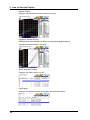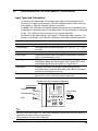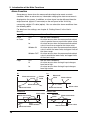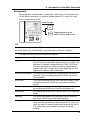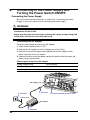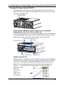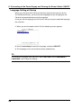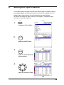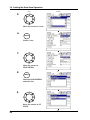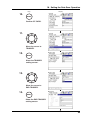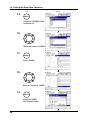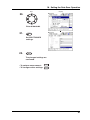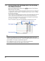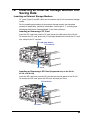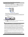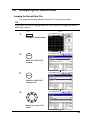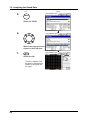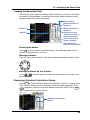
1
User's
Manual
XL100
Datum-Y
IM XL120P
クイックマニュアル
Quick Setup Manual
XL111, XL112, XL114
ポータブルデータロガ−(Datum-Y)
XL121, XL122, XL124
ポータブルデータステーション(Datum-Y)
XL111, XL112, XL114
Portable Data Logger (Datum-Y)
XL121, XL122, XL124
Portable Data Station (Datum-Y)
IM XL120P
1st Edition: Apr. 2007(YMI)
Introduction
Thank you for purchasing our XL100 Portable Data Station/Portable Data
Logger.
This Quick Setup Manual briefly describes the key operations as well as setting
examples of the XL100 upon actual measurement, so that you can operate the
XL100 for the first time.
In addition to this manual, the User’s Manual and Communication Function
Manual contained in the CD-ROM are available separately. The User’s Manual
provides detailed information regarding all of the functions and operations of the
XL100 excluding the communication functions. The Communication Function
Manual provides information necessary for using communication functions and
creating communication programs. Use them together with this Quick Setup
Manual. The Communication Function Manual is available only for the Portable
Data Station.
After reading this manual, keep it in an easily accessible place for later
reference. This manual will come in handy when you are unsure of how to
operate the product.
Notes
• The contents of this manual are subject to change without prior notice.
• Figures and illustrations representing display views in this manual may differ
from actual views.
• Every effort has been made to ensure accuracy in the preparation of this
manual. However, should any doubts arise or errors come to your attention,
please contact the vendor from which you purchased the product.
• The contents of this manual may not be transcribed or reproduced, in part or
in their entirety, without prior permission.
Trademarks
The company and product names referred to in this document are either
trademarks or registered trademarks of their respective holders.
Revisions
First Edition: April, 2007
1st Edition: April 2007 (YMI)
All Rights Reserved, Copyright © 2005, Yokogawa Meters & Instruments Corporation
IM XL120P
1
Safety Precautions
When operating the instrument, be sure to observe the cautionary notes given
in “Safety Precautions” on pages 4 and 5 and section 3.1, “Handling
Precautions” in the User’s Manual. If you use the instrument in any way other
than as instructed, the instrument’s protective measures may be impaired.
The following safety symbols are used on the instrument and in this manual.
WARNING
Indicates a hazard that may result in the loss of life or serious injury of the
user unless the described instruction is abided by.
CAUTION
Indicates a hazard that may result in an injury to the user and/or physical
damage to the product or other equipment unless the described instruction is
abided by.
Note
Indicates information that is essential for handling the instrument or should
be noted in order to familiarize yourself with the instrument’s operating
procedures and/or functions.
TIP
Indicates information that complements the present topic.
2
IM XL120P
Contents
Introduction ............................................................................. 1
Safety Precautions .................................................................. 2
1. Checking the Contents of the Package ........................ 4
2. Flow of Operation ........................................................... 5
3. Names and Functions of Parts ...................................... 6
4. How to View the Display ................................................. 9
5. Introduction of the Main Functions ............................. 15
Input Type and Calculation .................................................................. 15
Alarm Function ..................................................................................... 16
Saving Data ........................................................................................... 17
Triggers ................................................................................................. 18
File Operations ..................................................................................... 18
Communication Function .................................................................... 19
6.
Operation Mode and Basic Key Operations ............... 21
Operation Modes and Switching the Operation Mode ...................... 21
Switching the Display in Free Running Mode or Logging Mode ...... 22
Switching the menu in Setting Mode .................................................. 22
Key Operations for Entering Characters ............................................ 23
Key Operations for Entering Values .................................................... 23
7.
8.
Signal Wiring ................................................................. 24
Connecting to the Power Supply and Turning the
Power Switch ON/OFF .................................................. 26
Connecting the Power Supply ............................................................. 26
Turning the Power Switch ON/OFF ..................................................... 27
9. Setting the Input Channel ............................................ 29
10. Setting the Data Save Operation ................................. 33
11. Confirming the Settings and Performing the Measurement ............................................................................... 38
12. Inserting an External Storage Medium and Saving Data . 39
Inserting an External Storage Medium ............................................... 39
Starting the Data Save Operation ....................................................... 40
Stopping the Data Save Operation ..................................................... 40
13. Analyzing the Saved Data ............................................ 41
Loading the Saved Data File ................................................................ 41
Loading the Measured Data ................................................................. 43
Displaying Statistical Calculation Values ........................................... 43
IM XL120P
14. Troubleshooting ............................................................ 44
Index ....................................................................................... 45
3
1.
Checking the Contents of the Package
Unpack the box and check the contents before operating the instrument. Should
the product you have received be the wrong model, lack any items, or show any
problems in its appearance, contact the vendor from whom you purchased the
product.
Instrument Main Unit
Check the model and suffix code printed on the nameplate on the rear panel to
ensure that the XL100 is exactly as specified in your purchase order.
Model
XL100
No.
When inquiring about the product to
the vender, please also give the vendor
this number.
Accessories
Make sure that the package contains all the accessories listed below and that
they are all free from any damage.
These are attached to the XL100.
Terminal block unit
Rubber boot
Screwdriver for
terminals
+ ch
-1
b
+ ch
-2
b
+ ch
-3
b
+ ch
-4
b
+ ch
-5
b
+ ch
-6
b
+ ch
-7
b
+ ch
-8
1.
(Ex.: 95052)
Side cover
(Supplied with the
XL121, XL122, and
XL124)
AC adapter
Quick setup manual
(this manual)
CD-ROM
Contains Standard Software and
PDF manuals (User's Manual,
Quick Setup Manual, and
Communication Function Manual).
TIP
For details on peripherals and spare parts, see page 3 in the User’s Manual.
4
IM XL120P
2.
Flow of Operation
Reference page
in this manual
Reference chapter/
section in the
User’s Manual
Connect the wires
Page 24
3.3-3.5
Connect the power supply
and turn the power ON
Page 26
3.6, 4.1
Set the language
Page 28
Configure
Initial startup only
• Set the input
Page 29
Chapter 5
• Save the data
Page 33
9.1
Set other items (as necessary)
•
•
•
•
•
•
Alarm
Display
Calculation
Communications
Hardware
System
Chapter 6
Chapter 7
Chapter 8
Chapter 10
Chapter 4, 11, etc.
11.6, 11.7
Confirm the settings
Free Running Mode
and measure
Page 38
Save the data
Page 39
9.1
Page 41
• Review Mode
• Logging & Review Mode
9.2
Analyze the data
Logging Mode
Process the file (as necessary)
• Rename the file
• Delete the files
• Copy the data
IM XL120P
9.7
9.8
9.9
5
3.
Names and Functions of Parts
Front Panel
Terminal block unit
Display
Terminal block unit where
probes are connected.
For the wiring procedure,
see page 23.
Displays measured data, operation
status, setup menu, settings, etc.
For the viewing the displays,
see page 9.
Status display
section
Data display,
setting menu,
and setting
display section
HOME
REVIEW
FILE
TIME / DIV
SETTING
HOLD
SET
ESC
START
/ STOP
RANGE
DISPLAY
SAVE
GROUP
SELECT
MARK
Keys
Operation status LED
POWER : Illuminates when the power is ON
CHARGE : Illuminates when the battery is being charged
START :
Illuminates while logging
Keys
4
3
2
1
HOME
REVIEW
FILE
6
9
TIME / DIV
START
/ STOP
SETTING
HOLD
7
5
SET
ESC
10
RANGE
DISPLAY
12
SAVE
GROUP
8
11
13
SELECT
MARK
14
6
15
16
IM XL120P
3. Names and Functions of Parts
1. HOME Key
Press this key to enable Free Running Mode for measuring instantaneous values (see
page 21).
2. REVIEW Key
Press this key to enable Logging & Review Mode in which past measured data can be
viewed while logging (see page 21) or enable Review Mode in which saved data can
be analyzed (see page 21).
3. FILE Key
Press this key to enable File Operation Mode in which file names can be changed,
measured data can be copied, setting data can be saved or loaded, and so on (see
page 21).
4. SETTING Key
Press this key to set measurement conditions, conditions for saving measured data,
alarm conditions, etc.
5. HOLD Key
Press this key to hold the display so that the measured values are not updated or to
release the display. In addition, hold this key down to enable or disable key lock.
6. TIME/DIV Key
Press this key to switch the time axis (the time per grid (division)).
7. ESC Key
Press this key to cancel a key operation.
8. SET Key
Press this key to set settings entered through the keys.
9. START/STOP Key
Press this key to start/stop logging.
10. RANGE Key
Press this key to change the input range or span (scale).
11. DISPLAY Key
Press this key to switch the display in Free Running Mode or Logging Mode (see page
22). Press this key also to switch between marker display and statistical calculation
display in Review Mode.
12. SAVE Key
Press this key to manually save or print the measured data or screen data.
13. GROUP Key
Press this key to switch the displayed group of measurement, calculation, and
communication input channels.
14. Fast Forward Key
Press this key to move the marker to the left or right by 1 division on the review display
(see page 43).
15. MARK Key
Press this key to select a marker to be activated on the review display (see page 43).
16. Arrow/SELECT Key
Press the arrow keys to select items on the display. Press this key also to move the
marker to the left or right on the review display (see page 43).
Press the SELECT key to confirm a selection.
IM XL120P
7
3. Names and Functions of Parts
Side Panel
USB port for USB memory
For a description, see section 3.9.
Ethernet port*
CF card slot
For a description,
see section 3.8.
USB port for
connecting a PC*
For a description,
see section 4.7.
SD card slot*
For a description,
see section 3.8.
USB
The reference sections are those
of the User’s Manual.
For a description,
see section 4.7.
For details on how to insert
the CF card or SD card, see
page 39.
USB
DC INPUT
12V 20W MAX
CF
SG
SD
IN GND OUT
LOGIC/PULSE
POWER
LAN
Power switch
For a description,
see section 4.1.
AC adapter jack
For a description,
see section 3.6.
For details on connecting
the power supply and
turning the power ON/OFF,
see pages 26 and 27.
RS485
RS232
ALARM
TRIGGER
Trigger input/output terminal
For a description, see section 3.5.
Digital I/O connector
For a description, see section 3.4.
RS-232 connector*
For a description, see section 3.8.
RS-485 connector*
For a description, see section 3.8.
* Supported only on the XL121, XL122, and XL124
Rear Panel
Screwdriver for terminals (accessory)
Press the screwdriver towards the spring
(right in this figure) to detach it.
Name plate
Battery cover
Holds the lithium ion
battery (94009) sold
separately .
8
IM XL120P
4.
How to View the Display
Status Display Section
3 2 1
7
4
5
6
8
1. Operation Mode
Displays the mode: Free Running, Logging, Logging & Review, Setup, or
File Operation.
2. User name
Displays the login user name when the key login function (see section 11.7
in the User’s Manual) is turned ON.
3. Group Name (For the procedure to set groups, see section 7.2 in the
User’s Manual)
Displays the group name of the displayed measurement channel.
4. Alarm Status (For a description of the alarm function, see page 16)
The status is displayed using different icon colors as follows:
Gray:
Yellow-green:
Red:
No alarm setting
Alarm setting enabled
Alarm activated
5. Alarm Output Status
The status is displayed using different icon colors for each alarm output
channel (1 to 4) as follows:
Gray:
Yellow-green:
Red:
No alarm setting
Alarm setting enabled
Alarm outputting
6. Date/Time (For the procedure to set the date/time, see section 4.3 in the
User’s Manual)
Displays the year, month, day, hour, minute, and second.
7. Sampling Interval
Displays the sampling interval (measurement/save interval of measured
data) when in Free Running, Logging, or Logging & Review Mode.
8. Various Icons
The following icons are used to display the operation status, interface usage
status, etc.
An icon shown when the data save destination is set to internal memory. The
icon blinks when there is access to the internal memory. The icon is gray
when the data save destination is not set to internal memory.
IM XL120P
9
4. How to View the Display
An icon shown when the data save destination is set to internal memory and
the save mode is set to DIVISION. The icon blinks when there is access to
the internal memory.
An icon shown when the data save destination is set to internal memory and
the memory full operation is set to REPEAT. The icon blinks when there is
access to the internal memory.
An icon shown when the data save destination is set to internal memory and
the memory full operation is set to DELETE. The icon blinks when there is
access to the internal memory.
An icon shown when the data save destination is set to internal memory, the
save mode is set to DIVISION, and the memory full operation is set to
REPEAT. The icon blinks when there is access to the internal memory.
An icon shown when the data save destination is set to internal memory, the
save mode is set to DIVISION, and the memory full operation is set to
DELETE. The icon blinks when there is access to the internal memory.
An icon shown when the data save destination is set to CF card. The icon
blinks when there is access to the CF card. The icon is gray when the data
save destination is not set to CF card.
An icon shown when the data save destination is set to CF card and the save
mode is set to DIVISION. The icon blinks when there is access to the CF card.
An icon shown when the data save destination is set to CF card and the
memory full operation is set to REPEAT. The icon blinks when there is
access to the CF card.
An icon shown when the data save destination is set to CF card and the
memory full operation is set to DELETE. The icon blinks when there is access
to the CF card.
An icon shown when the data save destination is set to CF card, the save
mode is set to DIVISION, and the memory full operation is set to REPEAT.
The icon blinks when there is access to the CF card.
An icon shown when the data save destination is set to CF card, the save
mode is set to DIVISION, and the memory full operation is set to DELETE.
The icon blinks when there is access to the CF card.
An icon shown when the data save destination is set to SD card. The icon
blinks when there is access to the SD card. The icon is gray when the data
save destination is not set to SD card. (Supported only on the XL121, XL122,
and XL124.)
An icon shown when the data save destination is set to SD card and the save
mode is set to DIVISION. The icon blinks when there is access to the SD card.
(Supported only on the XL121, XL122, and XL124.)
An icon shown when the data save destination is set to SD card and the
memory full operation is set to REPEAT. The icon blinks when there is
access to the SD card. (Supported only on the XL121, XL122, and XL124.)
10
IM XL120P
4. How to View the Display
An icon shown when the data save destination is set to SD card and the
memory full operation is set to DELETE. The icon blinks when there is access
to the SD card. (Supported only on the XL121, XL122, and XL124.)
An icon shown when the data save destination is set to SD card, the save
mode is set to DIVISION, and the memory full operation is set to REPEAT.
The icon blinks when there is access to the SD card. (Supported only on the
XL121, XL122, and XL124.)
An icon shown when the data save destination is set to SD card, the save
mode is set to DIVISION, and the memory full operation is set to DELETE.
The icon blinks when there is access to the SD card. (Supported only on the
XL121, XL122, and XL124.)
An icon shown when there is data saved in the backup memory. The icon
blinks when there is access to the backup memory. The icon is gray when
there is no data saved to the backup memory.
An icon shown when the interface is set to LAN, LAN/RS-232, or LAN/RS-485. For
other cases, the icon is gray. (Supported only on the XL121, XL122, and XL124.)
An icon shown when the interface is set to USB. For other cases, the icon is gray.
(Supported only on the XL121, XL122, and XL124.)
An icon shown when the communication protocol is set to Modbus (slave).
The icon is gray when set to Modbus (master). (Supported only on the XL121,
XL122, and XL124.)
An icon shown when the communication protocol is set to Modbus (master).
The icon is gray when set to Modbus (slave). (Supported only on the XL121,
XL122, and XL124.)
An icon shown when the printer output is turned ON and the sampling interval
is greater than or equal to 1 minute. The icon is gray when the printer output
is OFF. (Supported only on the XL121, XL122, and XL124.)
An icon shown when the printer output is turned ON and the sampling interval
is less than or equal to 30 seconds. This indicates that only manual print is
valid using the SAVE key. (Supported only on the XL121, XL122, and XL124.)
An icon shown when the display update is held. The icon is gray when the
display is not held.
An icon shown when key lock is enabled. The icon is gray when key lock is
disabled.
An icon shown when the AC adapter is connected.
An icon shown when the AC adapter is not connected, and the XL100 is
running on a battery. Shows the remaining battery power using four levels
(
IM XL120P
→
→
→
).
11
4. How to View the Display
Data Display Section
Waveform & Digital Display
1
3
4
2
6 12
10
11
8
5
9
7
1. Waveform
Waveforms of measured data, calculated data, and communication input data.
Waveforms of logic input are shown at the lower section of the screen as shown in the
figure above.
2. Time Axis
Displays the time axis (time per grid (division)) specified by the TIME/DIV key.
3. Alarm Line
Displayed with a dotted line at the position of the alarm value of the selected channel
(active channel).
4. Scale Upper Limit
Shows the display upper limit of the active channel.
5. Scale Lower Limit
Shows the display lower limit of the active channel.
6. Pen
Displayed at the current value position of each channel. The active channel is shown
highlighted in reverse video.
7. Usage Indication Bar of the Storage Media
Displays using a blue bar the amount of space used with respect to the total space on
the storage medium that is specified to be the save destination of the measured data.
Total space on the save
destination medium
Used space
Free space
8. Grid
The grid can be turned ON/OFF.
12
IM XL120P
4. How to View the Display
9. Elapsed Time
Displays the elapsed time from the start of the logging operation.
10. Digital Display
Displays the current values of the measured data, calculated data, and
communication input data using numeric values.When an alarm is occurring, the
value is shown in red in reverse video.
11. Unit
Displays preset characters such as °C or an arbitrary specified characters (up to 6
characters).
12. Channel No./Tag
Displays the channel number and the specified tag (up to 8 characters). The
active channel is shown highlighted (reverse video).
Other Data Displays
In addition to the waveform & digital display, other displays are available including the
waveform display that does not show numeric values. For a description of the data
displays below, see section 2.3, “Data Display” in the User’s Manual.
• Digital Display
Displays the numeric values of the instantaneous values and statistical
calculation values.
• Bar Graph Display
Displays a bar graph in place of a waveform.
IM XL120P
13
4. How to View the Display
• Review Display
Displays the waveforms of data saved in the past.
• Logging & Review Display
Displays both the waveforms of data currently being logged and the
waveforms of data saved in the past.
• Alarm Summary Display
Displays the alarm status in a list.
• Log Display
Displays the log data of error messages and communications.
14
IM XL120P
5.
Introduction of the Main Functions
Input Type and Calculation
As shown in the table below, the available input types are analog input, which
includes DC voltage, thermocouple, and RTD, and other inputs, which consist of
pulse signal (1 channel) and logic signals (2 channels).
In addition, the arithmetic calculations between two inputs can be performed and
assigned to a calculation channel and displayed in the same fashion as measured
values. The statistics of measured values can also be displayed.
For details on the input settings, see chapter 5, “Setting the Input Channels.” For
details on calculation, see chapter 8, “Setting the Calculation of Measured Data.”
Input/Calculation
Description
DC voltage
Measures a DC voltage in the range of ±100 mV to ±50 V.
Thermocouple
Selectable from the following types: R, S, B, K, E, J, T, N, W,
L, and U.
RTD
Selectable from Pt100 and JPt100 types.
Pulse signal
Displays the pulse input as number of revolutions, integrated
value, or instantaneous value.
Logic signal
Displays the logic waveform at the lower section of the display by
taking input voltage less than or equal to 0.9 V to be OFF (0) and
input voltage greater than or equal to 2.1 V to be ON (1).
Calculation
Performs arithmetic calculations using measured data,
calculated data, communication data, and arbitrary assigned
constants and displays the result.
Statistical calculation
Calculates and displays the maximum, minimum, average,
peak (P-P), or rms value of the measured value.
Displays the measured/calculated data
Signal input
Voltage
Thermocouple
Pulse/Logic
input
RTD
TIP
You must connect a digital I/O cable sold separately to the input terminal (digital I/O
connector) to apply pulse or logic signals.
(See section 3.4 in the User's Manual.)
IM XL120P
15
5. Introduction of the Main Functions
Alarm Function
Generates an alarm when the measured/calculated value meets a certain
condition. When an alarm occurs, information notifying the alarm occurrence is
displayed on the screen. In addition, an alarm signal can be delivered from the
output terminal (digital I/O connector) on the rear panel of the XL100 by
connecting a digital I/O cable (option). You can select the alarm conditions from
the following table.
For details on the settings, see chapter 6, “Setting Alarms” in the User’s
Manual.
Input Type
Setting
Alarm Condition
Level
or Pulse
OFF
Hi
Not set alarm conditions.
An alarm occurs when the measured/calculated
value is greater than or equal to the alarm value.
An alarm occurs when the measured/calculated
value is less than or equal to the alarm value.
An alarm occurs when the measured/calculated
value is within the lower limits and upper limits of
the alarm range.
An alarm occurs when the measured/calculated
value is outside the lower limits and upper limits
of the alarm range.
Lo
Window IN
Window OUT
Logic
OFF
Hi
Not set alarm conditions.
An alarm occurs when the logic input changes
from low to high.
An alarm occurs when the logic input changes
from high to low.
Lo
Lo
Hi
Alarm
value
Alarm occurrence
Measured
Alarm release
value
Alarm release
Alarm value
Alarm occurrence
Measured value
Window OUT
Window IN
Alarm value
Alarm occurrence
Alarm release
Measured value
16
Measured
value
Alarm occurrence
Alarm release
Alarm value
IM XL120P
5. Introduction of the Main Functions
Saving Data
Measured data, calculated data, setting data, and so forth can be saved to the
XL100 internal memory or an external storage medium (CF card or SD card)
that is inserted in the XL100.
Save the data
CF
SD
Supported only on the
XL121, XL122, and XL124
TIP
The XL100 is equipped with a USB port for USB memories. However, data cannot
be saved directly to a USB memory (see section 3.9 in the User’s Manual).
The types of data that can be saved are as follows:
Type
Description
Logging data
The instantaneous values of the measured/calculated data
can be saved at a specified sampling interval. The data save
operation is started or stopped with the START/STOP key.
The save operation can also be started or stopped when a
specific event (see “Trigger” on the next page) occurs. The
logging data contains alarm information.
Manual sampled data
The measured/calculated data (instantaneous values) of all
channels can be saved by pressing the SAVE key in Free
Running Mode.
Alarm data
The same information as the alarm summary display can be
saved by pressing the SAVE key during alarm summary
display.
Screen image data
The image data of the screen being displayed can be saved
by pressing the SAVE key in Free Running Mode, etc.
Setting data
The setting data of the XL100 can be saved in File Operation
Mode.
Log data
The same information as the log display can be saved by
pressing the SAVE key during log data display.
Backup file
If the data save operation is not carried out normally to the
internal memory or external storage medium (CF card or SD
card), the data is saved to the backup memory of the XL100.
The saved data can be copied to an external storage
medium.
IM XL120P
17
5. Introduction of the Main Functions
Triggers
In addition to using the START/STOP key to start or stop the logging, a trigger
for starting (or stopping) the save operation of the logging data (measured/
calculated data) can be configured for automatic operation. The trigger for
logging can be selected from the list below and configured.
Type
Description
None
Not set trigger conditions.
External
A trigger is activated when a signal is applied to
the external trigger input terminal.
Level
High limit (H)
Low limit (L)
Window IN
Window OUT
Alarm
A trigger is activated when the measured value is greater
than or equal to the specified value.
A trigger is activated when the measured value is less than
or equal to the specified value.
A trigger is activated when the measured value is within the
specified lower and high limits.
A trigger is activated when the measured value is outside
the specified lower and high limits.
A trigger is activated when an alarm occurs on the specified
alarm output channel.
Time
A trigger is activated at the specified time.
Timer
The time at which the data save operation is stopped can
be specified. Logging is stopped after the specified time
elapses.
File Operations
The following file operations are available.
Operation Type
Description
Rename
Renames files saved on an external storage medium (CF card
or SD card) or internal memory.
Save setting data
Saves setting data to an external storage medium (CF card, SD
card, and USB memory), internal memory, or setting memory.
Load setting data
Loads the setting data saved on an external storage medium
(CF card, SD card, and USB memory), internal memory, or
setting memory and changes the settings.
Copy data
Copies the files saved to the an external storage medium (CF
card or SD card), internal memory, or setting memory to an
external storage medium (CF card, SD card, or USB memory),
internal memory, or setting memory.
Copy backup memory Copies the files saved to the backup memory (memory to which
data is saved when data cannot be saved to an external storage
medium or internal memory) to an external storage medium (CF
card or SD card) or internal memory.
Format
18
Formats an external storage medium (CF card or SD card),
backup memory, or internal memory.
IM XL120P
5. Introduction of the Main Functions
Communication Function (Supported only on the XL121, XL122, and XL124)
FTP Client/Server
The Ethernet interface can be used to automatically transfer measurement data
files to an FTP server connected to the network or access the XL100 from a PC
through FTP to retrieve data on the external storage medium or internal
memory of the XL100.
Automatically save
measured data
FTP client
Ethernet
Hub
Hub
FTP server
Load measured data
FTP server
Ethernet
Hub
Hub
PC
Web Server
By configuring the XL100 to be a Web server, the XL100 screen can be shown
on the PC. You can monitor the measured data and switch the display from the
PC.
Monitor the measured data
Ethernet
Web server
Hub
PC
Hub
Monitor the measured data
PC
IM XL120P
19
5. Introduction of the Main Functions
E-mail transmission
An e-mail can be sent automatically from the XL100 when an alarm occurs.
Receive e-mail
Ethernet
Send e-mail
Hub
PC
Hub
Receive e-mail
PC
Serial Communication
The USB interface or serial interface can be used to change the XL100 settings
from a PC or retrieve data into the PC through command communication. In
addition, Modbus communication is possible on the serial interface. The
Modbus master function enables the measured data of a measuring instrument
connected as a Modbus slave to be retrieved as communication input data. The
data can be assigned to a communication channel and displayed on the XL100
in a similar fashion to measurement and calculation channels.
Change settings and load data
Command
communication
PC
USB, RS-232, RS-485
Modbus master
Modbus slave
Modbus
communication
RS-232, RS-485
Measurement instrument
For details on the communication functions, see the Communication
Function Manual (contained in the CD-ROM).
20
IM XL120P
6.
Operation Mode and Basic Key
Operations
Operation Modes and Switching the Operation Mode
As shown in the figure below, the XL100 has six operation modes: (1) Free
Running Mode in which instantaneous values are measured, (2) Logging Mode
in which continuous measurement is performed while saving data, (3) Logging
& Review Mode in which past measured data can be viewed while the logging
operation is in progress, (4) Review Mode in which saved data is analyzed, (5)
File Operation Mode in which file operations such as saving and loading of the
setup data is performed, and (6) Setting Mode in which various settings such as
the measurement conditions are specified. The keys in the figure below are
used to switch between these modes.
HOME
REVIEW
Free Running Mode
Waveform
Switch the
display
Digital
Bar graph
Alarm summary
Log
System
information
START
/ STOP
Review Mode
Marker
measurement
FILE
SETTING
File Operation Mode
Setting Mode
File operation
menu
Set
Select
Rename files
Delete files
Setup file
Copy data files
Copy backup memory
Format
Logging Mode
Setting menu
Statistical
calculation
Initialize log
Select
Set
Input
Display
Data Save
Alarm
Calculation
Communication
Hardware
System
Waveform
Switch the
Digital
display
Bar graph
Alarm summary
Log
System
information
REVIEW
Logging & Review Mode
Marker measurement
Statistical
calculation
IM XL120P
21
6. Operation Mode and Basic Key Operations
Switching the Display in Free Running Mode or Logging Mode
To switch to a display other than waveform & digital display, press DISPLAY to
show the display switch pop-up menu, select the display using the arrow keys,
and press SELECT.
Select the display
Confirm the display
Display the menu
SELECT
DISPLAY
Switching the menu in Setting Mode
Press the arrow keys to select the desired item, and press SELECT. A
selection list, a setting window, or a setting menu that is one level lower is
displayed. To return to the original setting menu, press ESC.
Select the setup item
Confirm the setup item
SELECT
ESC
22
IM XL120P
6. Operation Mode and Basic Key Operations
Key Operations for Entering Characters
For settings that require characters to be entered, a character entry window
opens as shown below.
To enter a character, press the arrow keys to move the cursor in the character
selection area, select the character, and press SELECT. To set the entered
value, press SET.
Character entry area
Character selection area
Backspace
Delete
Character type selection area
(A: alphabet characters. 0: numeric characters and symbols)
Key Operations for Entering Values
For settings that require a value to be entered, a value entry window opens as
shown below. Press the up and down arrow keys to increment or decrement
the value and the left and right arrow keys to move along the digits. To set the
entered value, press SET. The window will not close when you press SET if a
value outside the range is entered. Enter a value within the range.
IM XL120P
23
7.
Signal Wiring
Signal Input Wiring (for Clamp Screws)
Be sure to also read the precautions in section 3.3, “Wiring the Input Signal
Cable” in the User’s Manual when wiring cables.
CAUTION
Do not apply an input exceeding the following values. Otherwise, the XL100
may break down.
• Maximum input voltage
100 mV, 500 mV, and 1 V range and TC input: ±10 VDC
5 V, 10 V, 50 V, and 1-5V/f.s. range: ±60 VDC
• Maximum common mode noise voltage
30 VACrms (50/60 Hz) or ±60 VDC
Wiring Procedure
1. Open the terminal cover of the terminal block unit.
2. Wire the input signal cables to the input terminals.
As shown below, loosen the terminal screws using the screwdriver provided,
insert the signal wires, and fasten the terminal screws.
3. Close the terminal cover of the terminal block unit.
Terminal cover
Accessory screwdriver
for terminals
Enlarged view
Signal wire
Terminal block unit
TIP
The terminal block unit can be removed. For the procedure to remove the terminal
block unit, see section 3.3, “Wiring the Input Signal Cable” in the User’s Manual.
24
IM XL120P
7. Signal Wiring
Wiring Diagram
Use wires of the following specifications.
TC input
DC voltage input
–
ch
–
ch
–
+
+
+
+
DC voltage input
–
b
b
Extension leadwire
RTD input
A
+
B
ch
–
DC current input
b
b
A
B
+
+
+
b
–
–
b
Lead wire resistance per wire
of 10 Ω or less. Make the
resistance of the three wires equal.
ch
–
DC current input
Shunt resistor
Example: For 4 to 20 mA input, use a shunt
resistor of 250 Ω ± 0.1%.
Note
• For clamp terminals, use wires of the following specifications.
• Conductive cross-sectional area for single wire: 0.14 mm2 to 2.5 mm2,
stranded wire: 0.14 mm2 to 1.5 mm2
AWG: 26 to 14
• Length of the stripped section of the wire: Approx. 7 mm
Input signal wires whose diameter is 0.3 mm or less may not be securely
fastened. Fold over the conducting section of the wire, for example, to make
sure that the wire is securely fastened to the clamped terminal.
• RTD input terminals A (+) and B (–) are isolated on each channel. Terminal b
is shorted internally across all channels.
Other Wiring
• For a description of the pulse input, logic input, and alarm output wiring, see
section 3.4, “Wiring the Pulse Input, Logic Input, and Signal Cables” in the
User’s Manual.
• For a description of the external trigger input/output wiring, see section 3.5,
“Wiring the External Trigger I/O Signal Cables” in the User’s Manual.
IM XL120P
25
8.
Connecting to the Power Supply and
Turning the Power Switch ON/OFF
Connecting the Power Supply
Be sure to also read the precautions in section 3.6, “Connecting the Power
Supply” in the User’s Manual when connecting the power supply.
WARNING
• Use only the power cord and AC adapter supplied by YOKOGAWA Meters &
Instruments for the XL100.
• Check that the power source voltage matches the supply voltage rating (100
to 240 VAC), and then connect the power cord.
Connecting the AC Adapter
Follow the steps below to connect the AC adapter.
1. Check that the power switch is OFF.
2. Connect the AC adapter to the AC adapter jack of the XL100.
3. Connect the plug of the power cord supplied with the AC adapter to the
power connector of the AC adapter.
4. Connect the other end of the power cord to the power outlet that meets the
power rating (requirements).
Power supply rating of the AC adapter
Supply voltage rating
100 to 240VAC
Allowable supply voltage range
90 to 264 VAC
Power supply frequency rating
50/60 Hz
AC adapter jack
2. Connect.
4. Connect.
1. Check that the power is OFF.
Power cord
AC adapter
3. Connect.
26
IM XL120P
8. Connecting to the Power Supply and Turning the Power Switch ON/OFF
Turning the Power Switch ON/OFF
The power switch is located on the right side panel of the XL100. To turn the
power ON, press the I (ON) side of the power switch. Press the O on the other
side to turn the power OFF.
Power switch
Power Switch Operation When the Side Cover Is Attached
(Supported only on the XL121, XL122, and XL124)
You can operate the power switch with the rubber boot and side cover attached
by opening the power switch cover. When attaching the accessory side cover,
fasten the side cover attachment screw to fix the cover to the XL100.
Side cover attachment screw
Open from this end.
Side cover
Power switch cover
Rubber boot
Display at Power ON
When the power is turned ON, the XL100 shows the startup screen followed by
the self-test screen. When the self-test completes normally, the XL100 shows
“Self Test OK” followed by the Waveform & Digital display of Free Running
Mode. For the corrective action when an error message is displayed, see
section 4.1, “Turning ON/OFF the Power Switch” in the User’s Manual.
IM XL120P
27
8. Connecting to the Power Supply and Turning the Power Switch ON/OFF
Language Setting at Startup
When you start up the XL100 for the first time (the first time you turn on the
XL100 after purchase), you must set the language that you are going to use.
Follow the procedure below to set the language.
Once you set the language, the XL100 will start up using the specified language
the next time.
1. When you turn the power switch ON, the following screen appears.
2. Use the arrow keys to select the language, and press SELECT.
3. The language is set, and a self-test starts automatically.
TIP
To change the language once you set it, press SETTING, select HARDWARE >
LANGUAGE, and change the setting.
28
IM XL120P
9.
Setting the Input Channel
This chapter explains the steps to set the input channel using an example in which a
thermocouple (type E, measurement range: 0.0 to 1000.0°C) is input to CH1. The
settings of other input channels are not changed from the default settings.
For details on setting the input channels, see chapter 5, “Setting the Input
Channels” in the User’s Manual.
Keys
1.
Display
SETTING
Change to Setting Mode.
2.
SELECT
Show the INPUT menu.
3.
SELECT
Show the ANALOG INPUT
setting screen.
4.
Move the cursor to CH01.
IM XL120P
29
9. Setting the Input Channel
Keys
Display
5.
SELECT
Show the CH01 setting
screen.
6.
Move the cursor to MODE.
7.
SELECT
Show the MODE selection
list.
8.
Move the cursor to TC.
9.
SELECT
Select TC.
30
IM XL120P
9. Setting the Input Channel
Keys
Display
10.
Move the cursor to
RANGE.
11.
SELECT
Show the RANGE
selection list.
12.
Move the cursor to E.
13.
SELECT
Select E.
14.
Move the cursor to
SPAN LOWER.
IM XL120P
31
9. Setting the Input Channel
Display
Keys
15.
SELECT
Show the SPAN LOWER
entry window.
16.
Enter 0.0.
17.
SET
Set SPAN LOWER settings.
18.
SET
The changed settings are
confirmed.
• To perform measurement:
• To configure other settings:
32
HOME
SETTING
IM XL120P
10.
Setting the Data Save Operation
This chapter explains the steps to save measured data using an example in
which the sampling interval is set to 1 min, the data save destination is set to
CF card, and the end trigger is set to timer (seven days later). The settings for
saving other measured data are not changed from the default settings.
For details on the settings for saving measured data, see section 9.1, “Setting
the Save Operation of Measured and Calculated Data” in the User’s Manual.
Keys
1.
Display
SETTING
Change to Setting Mode.
2.
Move the cursor to
DATA SAVE.
3.
SELECT
Show the DATA SAVE
setting screen.
4.
SELECT
Show the SAMPLING
INTERVAL selection list.
IM XL120P
33
10. Setting the Data Save Operation
Keys
Display
5.
Move the cursor to 1 min.
6.
SELECT
Select 1 min.
7.
Move the cursor to
SAVE MEDIA.
8.
SELECT
Show the SAVE MEDIA
selection list.
9.
Move the cursor to CF
CARD.
34
IM XL120P
10. Setting the Data Save Operation
Keys
Display
10.
SELECT
Confirm CF CARD.
11.
Move the cursor to
TRIGGER.
12.
SELECT
Show the TRIGGER
setting screen.
13.
Move the cursor to
END TRIGGER.
14.
SELECT
Show the END TRIGGER
setting screen.
IM XL120P
35
10. Setting the Data Save Operation
Keys
Display
15.
SELECT
Show the TRIGGER TYPE
selection list.
16.
Move the cursor to TIMER.
17.
SELECT
Select TIMER.
18.
Move the cursor to TIMER.
19.
SELECT
Show the TIMER
SETTINGS window.
36
IM XL120P
10. Setting the Data Save Operation
Display
Keys
20.
Enter 0168:00:00.
21.
SET
Set END TRIGGER
settings.
22.
SET
The changed settings are
confirmed.
• To perform measurement:
• To configure other settings:
IM XL120P
HOME
SETTING
37
11.
Confirming the Settings and Performing
the Measurement
When you are done with the settings, press HOME to switch to Free Running
Mode and check the settings.
The figure below shows the display that appears when the XL100 is configured
as explained in section chapter 9, “Setting the Input Channel” and 10, “Setting
the Data Save Operation.”
Check whether the displayed values are correct. If the measured values are not
correct, switch back to Setting Mode, and check that the input settings are
correct. If the measured values are not correct even though the input settings
are correct, see chapter 14, “Troubleshooting.”
If the CF Card icon is gray, the save destination is not set to the CF card.
Sampling interval CF card icon
Scale upper limit
Measured
value
Scale lower limit
TIP
• To switch to a display other than waveform & digital display, press DISPLAY to
show the display switch pop-up menu, select the display using the arrow keys, and
press SELECT. (The steps are explained in page 22.)
• Press TIME/DIV to switch the time axis (the time per grid (division)).
• Press RANGE to change the input range or span (scale).
38
IM XL120P
12.
Inserting an External Storage Medium and
Saving Data
Inserting an External Storage Medium
CF cards (Type II) and SD cards can be used on the XL100 as external storage
media.
For the handling precautions of the external storage media, the estimated
amount of stored data, and other information, see section 4.7, “Inserting and
Removing the External Storage Media” in the User’s Manual.
Inserting or Removing a CF Card
Insert the CF card firmly into the CF card slot on the side panel of the XL100.
To remove the CF card, press the CF card eject button to the left of the CF card
slot, and pull the CF card out.
CF card eject button
CF card slot
CF card
Inserting or Removing a SD Card (Supported only on the XL121,
XL122, and XL124)
Insert the SD card firmly into the SD card slot on the side panel of the XL100.
To remove the SD card, press the SD card, and then pull it out.
SD card slot
SD card
IM XL120P
39
12. Inserting an External Storage Medium and Saving Data
Starting the Data Save Operation
To start the data save (logging) operation, press /START
STOP . When the data save
operation starts, the START LED illuminates. If a start trigger (see page 18) is
specified, the logging operation starts when the trigger condition is met. The
START LED blinks until the trigger condition is met.
HOME
REVI
START LED
TIME
START
/ STOP
RANGE
START/STOP key
Usage Indication of the External Storage Media
The amount of space used is displayed using a blue bar with respect to the total
space on the storage medium that is specified to be the save destination of the
measured data.
Total space on the save
destination medium
Used space
Free space
Stopping the Data Save Operation
Press /START
STOP . If a stop trigger (see page 18) is specified, the logging operation
stops automatically when the trigger condition is met.
TIP
• A file name “YYMMDDhhmmss.DLO” (YY: year, MM: month, DD: day, hh: hour, mm:
minute, ss: second) is automatically assigned to measurement data files
(“YYMMDDhhmmss.CSV” if the data type is set to ASCII). You can also assign an
arbitrary file name. For the procedure to assign an arbitrary file name, see section 9.1,
“Setting the Save Operation of Measured and Calculated Data” in the User’s Manual.
• The measured/calculated data (instantaneous values) can be saved by pressing
SAVE in Free Running Mode. For the procedure to save the data manually, see
section 9.3, “Manually Saving Measured and Calculated Data” in the User’s Manual.
• The saved data file can be renamed, deleted, or copied to another external storage
medium in File Operation Mode. For these operations, see sections 9.7 to 9.9 in the
User’s Manual.
• If the data fails to be written to the save destination for some reason, the data is
saved to the backup memory. For details on the backup memory, see section 9.1,
“Manually Saving Measured and Calculated Data” in the User’s Manual.
40
IM XL120P
13.
Analyzing the Saved Data
Loading the Saved Data File
The steps to load measured data saved to a CF card is given below.
TIP
If you press REVIEW in Logging Mode, the XL100 switches to Logging & Review
Mode (see page 21).
Keys
1.
Display
REVIEW
Change to Review Mode.
2.
SELECT
Show the LOAD FILE
window.
3.
SELECT
Show the LOAD FILE
selection list.
4.
Move the cursor to CF
CARD.
IM XL120P
41
13. Analyzing the Saved Data
Keys
Display
5.
SELECT
Select CF CARD.
6.
Move the cursor to the file
shown in the FILE area.
7.
SET
Select the file.
The file is loaded, and
the data is displayed as
shown in the figure on
the right.
42
IM XL120P
13. Analyzing the Saved Data
Loading the Measured Data
Two markers (three markers including marker ALM when an alarm is activated)
are shown in Review Mode. A measured value at an arbitrary position can be
read by moving the markers horizontally.
Active maker
Measured value at
marker A
Measured value at
marker B
Difference in the
measured values or
calculated values
Marker A
Marker B
Time at the active
marker position
Time difference
between the markers
Selecting the Marker
Press MARK to select marker A and B alternately. The selected marker (active
marker) is displayed with a thick line.
Moving the Marker
Press the left or right arrow key. Hold the key down to move the marker quickly.
Moving the Marker by One Division
Press
(fast forward key) to move the active marker to the left or right
by one division.
Displaying Statistical Calculation Values
Press DISPLAY in Review Mode to display the maximum, minimum, average, peak
(P-P), and rms values from the start to the end of the logging operation. Press
SET to perform statistical calculation between markers A and B. Press DISPLAY
again to return to the marker display.
Statistical calculation
values
IM XL120P
43
14.
Troubleshooting
The table below lists the major symptoms and their corrective actions. For the
procedure to check the items under “Things to Check”, see the referenced
section written in section 12.1, “Troubleshooting” in the User’s Manual. For the
corrective action for error messages, see the referenced section written in
section 12.2, “Messages and Their Corrective Actions” in the User’s Manual.
Symptom
Things to Check
Nothing appears even when
the power is turned ON.
For AC power operation
• Check that the power cord is properly connected to the
power outlet.
• Check that the power supply is within the allowed
supply voltage range.
For battery operation
• Check that the battery is loaded correctly.
• Check that the battery is charged adequately.
The measurement display
is odd.
• Check that noise is not riding on the input
signal.
• Check that the wires are correctly connected.
• Check that the ambient temperature and
humidity are within the allowed specifications.
Keys do not work.
Check that the key lock (
right corner of the display.
Unable to save/load from the
memory.
• Turn the power switch OFF and then back internal
ON. It may be restored by the power-on self-test.
• There may have been a power problem while the
internal memory was being accessed. Format the
internal memory in File Operation Mode. Note that the
data saved in the memory will be lost in the process.
Unable to save/load from the
external storage medium.
• Check that the external storage medium is correctly
inserted.
• Check that the external storage medium is formatted.
• Check that there is sufficient free space on the external
storage medium.
Unable to set or control the
instrument using
communication commands.
• Check that the communication parameters are matched.
• Check that the specifications of the cable is suitable for
the application.
• Check that the electrical specifications are correct.
Unable to print.
• Check that the printer is turned ON.
• Check that the specifications of the connection cable are
correct.
• Check that the cable is correctly connected.
• Check that the communication parameters on the XL100
and printer are matched.
• Check that the chart is loaded correctly in the printer.
44
) is not shown at the upper
IM XL120P
Index
A
E
AC adapter 11, 26
accessories 4
active channel 12
active marker 43
alarm 16, 18
alarm data 17
alarm function 16
alarm line 12
alarm output status 9
alarm status 9
alarm summary display 14
arrow keys 7
e-mail transmission 20
elapsed time 13
ESC key 7
external storage medium 39
external trigger 18
B
backup file 17
backup memory 11
bar graph display 13
battery 8, 11
battery, remaining power 11
C
CF card 10, 17, 39
channel No. 13
character entry 23
CHARGE LED 6
communication function 19
copy backup memory 18
copy data 18
F
fast forward key 7, 43
FILE key 7, 21
File Operation Mode 21
file operations 18
format 18
Free Running Mode 21
front panel 6
FTP server 19
G
grid 12
GROUP key 7
group name 9
H
hold 11
HOLD key 7
HOME key 7, 21, 38
I
D
data save operation, setting of 33
data save operation, starting of 40
data save operation, stopping of 40
data, saving of 17
date/time 9
DC current 25
DC voltage 15, 25
differential calculation 15
digital display 13
DISPLAY key 7, 22, 43
display switching 22
IM XL120P
icons 9
input settings 29
input type 15
internal memory 9, 17, 18
K
key lock 11
keys 6
45
Index
L
S
level 18
load setting data 18
log data 17
log display 14
logging & review display 14
Logging & Review Mode 21
logging data 17
Logging Mode 21
logic 15
sampling interval 9, 33
SAVE key 7
save setting data 18
saved data file, loading of 41
scale 12
screen image data 17
SD card 10, 39
SELECT key 7
serial communication 20
SET key 7
setting data 17
SETTING key 7, 21, 29, 33
Setting Mode 21
side panel 8
signal input wiring 24
START LED 6, 40
START/STOP key 7, 21, 40
Statistical Calculation 15
statistical calculation 43
status display section 6, 9
storage media, usage indication bar of 12
M
manual print 11
manual sampled data 17
MARK key 7, 43
marker 43
measured data, loading of 43
menu switching 22
Modbus 11, 20
model 4
O
operation mode 9, 21
P
Pen 12
POWER LED 6
power supply, connection of 26
power switch, turning ON/OFF of 27
printer 11
pulse 15
R
RANGE key 7
rear panel 8
rename 18
review display 14
REVIEW key 7, 21, 41
Review Mode 21, 43
RS-232 8, 20
RS-485 8, 20
RTD 15, 25
46
T
tag 13
terminal block unit 6
terminal cover 24
thermocouple 15, 25, 29
time 18
time axis 12
TIME/DIV key 7
timer 18, 33
triggers 18
U
unit 13
usage indication of the external storage
media 40
USB 20
user name 9
V
values, entry of 23
IM XL120P
Index
W
waveform 12
Web server 19
IM XL120P
47
Memo
48
IM XL120P
Memo
IM XL120P
49
Memo
50
IM XL120P