1
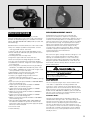
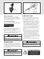
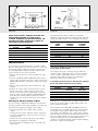
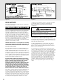
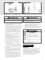
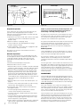
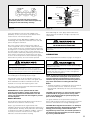
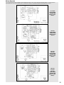
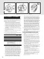
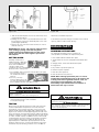
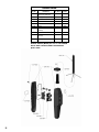
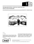
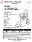
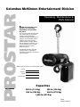
PROSTAR
Columbus McKinnon Entertainment Division
Operating, Maintenance &
Parts Manual
Follow all instructions and
warnings for inspecting,
maintaining and operating
this hoist.
The use of any hoist presents some
risk of personal injury or property
damage. That risk is greatly
increased if proper instructions and
warnings are not followed. Before
using this hoist, each operator
should become thoroughly familiar
with all warnings, instructions, and
recommendations in this manual.
Retain this manual for future
reference and use.
Forward this manual to the hoist
operator. Failure to operate the
equipment as directed in the manual
may cause injury.
Before using the hoist, fill in the information below:
Capacity
Serial No.
Voltage
Purchase Date
Capacities
250 lb (113 Kg)
300 lb (136 Kg)
500 lb (226 Kg)
600 lb (272 Kg)
1,000 lb (453 Kg)
20875
Revision P620-G
LIFETIME WARRANTY
Every Columbus McKinnon Corporation
hoist is thoroughly inspected and
performance tested prior to shipment from
the factory. If any properly installed,
maintained and operated hoist as outlined in
the applicable accompanying Columbus
McKinnon hoist manual develops a
performance problem due to defective
materials or workmanship as verified by
Columbus McKinnon Corporation, repair or
replacement of the hoist will be made to the
original purchaser without charge and the
hoist will be returned, transportation prepaid.
This warranty does not apply where
deterioration is caused by normal wear,
abuse, improper or inadequate power supply,
improper or inadequate maintenance,
eccentric or side loading, overloading,
chemical or abrasive actions, excessive heat,
unauthorized modifications or repairs, or use
of non-Columbus McKinnon Corporation
repair parts. EXCEPT AS STATED HEREIN,
COLUMBUS MCKINNON CORPORATION
MAKES NO OTHER WARRANTIES,
EXPRESS OR IMPLIED, INCLUDING
WARRANTIES OF MERCHANTABLILITY AND
FITNESS FOR A PARTICULAR PURPOSE.
Alterations or modifications of equipment and use of
non-factory repair parts can lead to dangerous
operation and injury.
TO AVOID INJURY:
• Do not alter or modify equipment
• Do not use equipment to lift, support or otherwise
transport people
• Do not suspend unattended loads over people
®
Country Club Road
P.O. Box 779
Wadesboro, North Carolina 28170
Phone (800) 477-5003
Fax (800) 374-6853
© 2008CM®
140 John James Audubon Parkway
Amherst, New York 14228-1197
Phone (800) 888-0985
Fax (800) 210-9480
Printed in USA
12/08
SAFETY PRECAUTIONS
Each Prostar Electric Hoist is built in accordance with the specifications contained herein and at the time of manufacture
complied with our interpretation of applicable sections of the National Electrical Code (ANSI/NFPA 70). Installers are required
to provide current overload protection and grounding in keeping with the code. Check each installation for compliance with the
applicable sections of the code as well as the National, State and Local Codes that may apply to the installation. In addition,
safety code requirements associated with the operation of a hoist in the inverted (theatrical) position (chain port up), as with
any mechanical equipment, vary depending upon locality. Therefore, before installing the hoist, the user should consult his
insurance company and/or local authority to see if a deviation is required to permit the use of the hoist in this particular
application.
The safety laws for elevators, lifting of people and for dumbwaiters specify construction details that are not incorporated into
the hoists. For such applications, refer to the requirements of applicable state and local codes, and the American National
Safety Code for elevators, dumbwaiters, escalators and moving walks (ASME A17.1). We cannot be responsible for
applications other than those for which the equipment is intended.
THIS SYMBOL POINTS OUT IMPORTANT SAFETY INSTRUCTIONS WHICH IF NOT
FOLLOWED COULD ENDANGER THE PERSONAL SAFETY AND/OR PROPERTY OF
YOURSELF AND OTHERS. READ AND FOLLOW ALL INSTRUCTIONS IN THIS
MANUAL AND ANY PROVIDED WITH THE EQUIPMENT BEFORE ATTEMPTING TO
OPERATE YOUR PROSTAR HOIST.
WARNING
Improper operation of a hoist can create a potentially hazardous
situation which, if not avoided, could result in death or serious
injury. To avoid such a potentially hazardous situation, the operator
shall:
1.
2.
3.
4.
5.
6.
7.
8.
9.
10.
11.
12.
13.
14.
15.
16.
17.
18.
19.
20.
21.
22.
23.
24.
25.
26.
1
NOT operate a damaged, malfunctioning or unusually
performing hoist.
NOT operate the hoist until you have thoroughly read
and understood this Operating, Maintenance and Parts
Manual.
NOT operate a hoist which has been modified.
NOT lift more than rated load for the hoist.
NOT use hoist with twisted, kinked, damaged, or worn
load chain.
NOT use the hoist to lift, support, or transport people.
NOT lift loads over people.
NOT operate a hoist unless all persons are and remain
clear of the supported load.
NOT operate unless load is centered under hoist.
NOT attempt to lengthen the load chain or repair
damaged load chain.
Protect the hoist’s load chain from weld splatter or other
damaging contaminants.
NOT operate hoist when it is restricted from forming a
straight line from hook to hook in the direction of loading.
NOT use load chain as a sling, or wrap load chain
around load.
NOT apply load to the tip of the hook or to the hook latch.
NOT apply the load unless load chain is properly
seated in the chain wheel(s) or sprocket(s).
NOT apply load if bearing prevents equal loading on all
load supporting chains.
NOT operate beyond the limits of the load chain travel.
NOT leave load supported by the hoist unattended
unless specific precautions have been taken.
NOT allow the load chain or hook to be used as an
electrical or welding ground.
NOT allow the load chain or hook to be touched by a
live welding electrode.
NOT remove or obscure the warnings on the hoist.
NOT operate a hoist on which the safety placards or
decals are missing or illegible.
NOT operate a hoist unless it has been securely
attached to a suitable support.
NOT operate a hoist unless load slings or other
approved single attachments are properly sized and
seated in the hook saddle.
Take up slack carefully - make sure load is balanced
and load holding action is secure before continuing.
Shut down a hoist that malfunctions or performs
unusually and report such malfunction.
27. Make sure hoist limit devices function properly.
28. Warn personnel of an approaching load.
CAUTION
Improper operation of a hoist can create a potentially hazardous
situation which, if not avoided, could result in death or serious
injury. To avoid such a potentially hazardous situation, the operator
shall:
1.
2.
3.
4.
5.
6.
7.
8.
9.
10.
11.
12.
13.
14.
15.
Maintain a firm footing or be otherwise secured when
operating the hoist.
Check brake function by tensioning the hoist prior to
each lift operation.
Use hook latches. Latches are to retain slings, chains,
etc. under slack conditions only.
Make sure the hook latches are closed and not
supporting any parts of the load.
Make sure the load is free to move and will clear all
obstructions.
Avoid swinging the load or hook.
Make sure hook travel is in the same direction as shown
on the controls.
Inspect the hoist regularly, replace damaged or worn
parts, and keep appropriate records of maintenance.
Use factory parts when repairing the unit.
Lubricate load chain per instructions in this manual.
NOT use the hoist load limiting or warning device to
measure load.
NOT use limit devices as routine operating stops
unless allowed by manufacturer. They are emergency
devices only.
NOT allow your attention to be diverted from operating
the hoist.
NOT allow the hoist to be subjected to sharp contact
with other hoists, structures, or objects through misuse.
NOT adjust or repair the hoist unless qualified to
perform such adjustments or repairs.
TABLE OF CONTENTS
Safety Precautions .............................................................1
Specifications......................................................................2
Installation ..........................................................................3
Operating Instructions ........................................................5
Maintenance .......................................................................6
Trouble Shooting ..............................................................10
Electrical Data...................................................................11
Disassembly-Assembly ....................................................13
Repair Parts......................................................................14
Exploded View..................................................................16
Replacement Parts List ....................................................18
Warranty ............................................................Back Cover
Figure 1A
Figure 1B
SPECIFICATIONS
REPAIR/REPLACEMENT POLICY
The Prostar Electric Chain Hoist is a highly versatile
materials handling device that can be used to lift loads that
are within its rated load capacity. It is available in five load
ratings: 250, 300, 500, 600 and 1,000 pounds (113,136, 226,
272 and 453 kg).
Standard features of the Prostar Electric Chain Hoist include:
• Alloy steel, oblique lay liftwheel that provides constant
chain speed and reduces chain wear.
• Hoistaloy® load chain for long and dependable service.
• Grease lubricated, hardened spur gears provide smooth
and quiet operation.
• Thermally protected, hoist duty motor.
• Forged steel upper and lower hooks with latch.
• Protector™ that prevents lifting dangerous overloads.
• D.C. disc type motor brake plus regenerative braking.
• Standard Less Chain Unit. Longer lifts can be supplied on
a per order basis.
• 3 foot (.9 M) power cord with provisions for grounding is
standard on 115-50/60, 220-1-50 and three phase units.
• 3 foot (.9M) is standard for all control cords. Longer cords
can be provided on a per order basis.
• Lightweight die cast aluminum frames and covers.
• Ball or needle bearings at all rotating points.
• Compact, yet rugged, design provides minimum
headroom and long, trouble-free service.
• 6 fpm (1.8 m/min) lift speed available on 1000 lbs (453 kg)
units.
• 8 fpm (2.4 m/min) lift speed available on 500-600-1000 lbs
(226, 272 and 453 kg) units.
• 12 fpm (3.6 m/min) lift speeds available on 500-6001000 lbs (226, 272 and 453 kg) units.
• 16 fpm (4.9 m/min) lift speeds available on 250-300500 lbs (113, 136 and 226 kg) units.
• 20 fpm (6.1 m/min) lift speeds available on 500-600 lbs
(226 and 272 kg) units.
• 24 fpm (7.3 m/min) lift speeds available on 250-300500 lbs (113, 136 and 226 kg) units.
• 40 fpm (12.2 m/min) lift speeds available on 250-300 lbs
(113 and 136 kg) units.
• 220-1-50, 380 to 460-3-50/60, 220 to 240-3-50/60 and
575-3-60 units available. Lift speeds are based on 60
hertz power supply. For 50 hertz power supply lift speeds
will be 5/6 of those indicated.
• UL and cUL listed.
• Lifetime Warranty.
All Prostar Electric Chain Hoists are inspected and
performance tested prior to shipment. If any properly
maintained hoist develops a performance problem, due to a
material or workmanship defect, as verified by the factory,
repair or replacement of the unit will be made to the original
purchaser without charge. This repair/replacement policy
applies only to Prostar Hoists installed, maintained and
operated as outlined in this manual, and specifically
excludes hoists subject to normal wear, abuse, improper
installation, improper or inadequate maintenance, hostile
environmental effects and unauthorized
repairs/modifications.
We reserve the right to change materials or design if, in our
opinion, such changes will improve our product. Abuse,
repair by an unauthorized person, or use of non-factory
replacement parts voids the guarantee and could lead to
dangerous operation. All Prostar Electric Chain Hoists are
backed with a lifetime warranty. Refer to the back cover for
details and limitations.
Alterations or modification of hoist and use of non-factory repair
parts can lead to dangerous operation and injury.
TO AVOID INJURY:
• Do not alter or modify equipment.
• Do use only factory replacement parts.
ACCESSORIES
Chain Container
This accessory item (Figure 1A) is used to hold the slack
chain and it is supplied with mounting hardware and
instructions. Chain containers are recommended for those
applications where slack chain will interfere with the load or
drag on the floor as may more often be the case with the
Double-reeved, 500, 600 and 1,000 lbs, (226, 272 and 453
kg) units. Chain containers are shipped separately and can
be furnished for units already in service.
Latchlok® Hooks
Latchlok Hooks (Figure 1B) are available to replace the
standard lower latch type hooks. The unique design of the
Latchlok Hook assures that it will stay locked until the
operator releases it by depressing the release button. It will
not open accidentally–even if the load chain goes slack.
Once opened, it can be shut with one hand or the weight of
the load when it is lifted. Latchlok Hooks can be supplied
with the hoist or they can be provided in kit form for hoists
already in service.
2
Claim Procedure
Figure 2A
Figure 2B
BC Series Beam Clamps
The beam clamps are ideal as anchors for rigging
applications (Figure 2A). The BC series clamps can be
adjusted to fit a wide range of beam sizes. The lightweight
and compact design makes the beam clamps ideal for
repeated set-ups and tear-downs.
POWER SUPPLY SYSTEM
Entertainment Rigging Products
Refer to sales Bulletin No. EPD-10B for additional rigging
products that can be used in the entertainment industry.
INSTALLATION
UNPACKING
After opening the carton (Figure 2B) , carefully inspect the
hoist frame, cords, hooks, chain and control station for
damage that may have occurred during shipment. If there is
damage, refer to the packing slip envelope.
Make sure that the power supply (Figure 3A) to which the
hoist is to be connected is the same as that shown on the
identification plate located on bottom of hoist.
Operating a unit with obvious external damage may cause load to
drop and that may result in personal injury and/or property
damage.
TO AVOID INJURY:
Carefully check unit for external damage prior to installation.
(Refer to Figure 4A or 4B on page 5). To insure proper
operation, to avoid damage to hoist and electrical system
and to reduce the risk of electric shock or fire, the branch
circuit supplying power to the hoist must:
1. Have ample capacity to prevent excessive voltage drop
during starting and operation (refer to “Checking for
Adequate Voltage at Hoist” on page 4). When determining
the size of branch circuit components and conductors,
special consideration should be given to the starting
current-amps (approximately three times that shown on
the hoist identification plate) and the length of the
conductors. As a minimum, the system should be rated for
15 amps and it should have #16 AWG, or larger, wiring.
2. Be in accordance with the National Electrical Code
(ANSI/NFPA-70) and applicable National, State and Local
Codes.
3. Effectively ground the hoist in accordance with National
Electrical Code and other applicable codes. Proper
grounding provides a path of least resistance for electric
current to reduce the risk of electric shock. The power
cord of the hoist includes a green-yellow wire for
grounding the hoist to the external power supply system.
Be sure that the receptacle opening that receives the
longest prong is properly grounded. If grounding is to be
through the trolley trackwheels, each section of the runway
must be grounded to the building ground system using
metal to metal connections.
4. Include slow blow type fuses or inverse trip time circuit
breakers to permit the hoist to start and accelerate load.
MOUNTING THE HOIST
Attach the hoist to the truss/structure to be lifted using the
mounting hook (Figure 3B) . Be sure that the attachment
point is held in the lowermost part of the hook arc and the
latch is tightly against the hook tip. Also, the attachment
point must have sufficient strength to withstand several times
the load imposed. If in doubt, consult a registered engineer
and local building codes.
An inadequate attachment point may allow the hoist and load to
fall and cause injury and/or property damage.
TO AVOID INJURY:
Make sure the attachment point has sufficient strength to hold
several times the hoist and its rated load.
3
Failure to properly ground the hoist presents the danger of electric
shock.
TO AVOID INJURY:
Permanently ground the hoist as instructed in this manual.
5. Include a disconnecting means capable of being locked
in the “open” position.
Load Hook
Name
plate
Same
Chain
Stop
Loose
End of
Chain
Power supply
Making sure the hoist will operate on
the power supply system
Power
Cord
Control
Station
Mounting Hook
Figure 3A
Figure 3B
NOTE: IN THIS MANUAL, NOMINAL VOLTAGES ARE
USED WHEN REFERRING TO POWER SUPPLY
SYSTEMS. HOWEVER, WITH NO MODIFICATION, THE
PROSTAR HOIST WILL OPERATE ON A RANGE OF
VOLTAGES AS INDICATED BELOW:
For proper operation and to avoid these low voltage
problems, voltage (measured at end of the power cord while
lifting rated load) should be as the following chart indicates.
NOMINAL
VOLTAGE
230
460
220
380
415
575
VOLTAGE
RANGE
208-240
440-480
200-240
365-395
400-430
550-600
HERTZ
60
60
50
50
50
60
Three Phase Hoists
Since the motor in a three phase hoist can rotate in either
direction, depending on the manner in which it is connected
to the power supply, the direction of hook movement must
be checked during the original installation and each time
hoist is moved to a new location as follows:
1. Move the manual disconnect switch handle to the “OFF”
position.
2. Connect the BROWN, GREY AND BLACK wires of hoist
power cord to load side of disconnect switch. Connect the
GREEN-YELLOW wire of hoist power cord to power supply
ground.
3. Move the manual disconnect switch handle to the “ON”
position.
4. Depress the (up) control. If the hook moves in the up
direction, the hoist is ready for operation. If the hook
lowers, move the disconnect switch handle to the “OFF”
position and interchange the BLACK and BROWN leads
at the disconnect switch. Move the disconnect switch
handle to the “ON” position and the hoist is now ready for
operation.
Checking for Adequate Voltage at Hoist
The hoist must be supplied with adequate electrical power
for proper operation and to reduce problems that may result
from insufficient power (low voltage). These include:
• Noisy hoist operation due to brake and/or contactor
chatter.
• Heating of the hoist motor and other internal components
as well as heating of wires and connectors in the circuit
feeding the hoist.
• Failure of the hoist to lift the load due to motor stalling.
• Blowing fuses or tripping circuit breakers.
• Dimming of lights or slowing of motors connected to the
same circuit.
NOMINAL
POWER
SUPPLY
115-1-50/60
220-1-50
208-3-60
220-3-50
230-3-60
380-3-50
415-3-50
460-3-60
575-3-60
MINIMUM
OPERATING
VOLTAGE
108
198
187
198
207
365
399
414
518
* MIN. VOLTAGE
AT INSTANT
OF START
103
182
172
182
190
336
367
380
506
*The drop in voltage upon energizing the hoist should
not be below the value listed.
Low voltage can also be caused by using an undersize
extension cord to supply power to the hoist. The following
charts should be used to determine the size wires in the
extension cord in order to minimize the voltage drop
between the power source and the hoist.
115-1-50/60 units with contactor, 220-1-50 units and three
phase units (hoists with black control station)
MAXIMUM LENGTH OF EXTENSION CORD
Wire Size
Single
Three
Phase Hoist
Phase Hoist
#16 A.W.G.
135 feet(40 M)
245 feet(73 M)
#14 A.W.G.
220 feet(66 M)
395 feet(120 M)
#12 A.W.G.
354 feet(107 M)
630 feet(192 M)
After the hoist is suspended from its support and you have
made sure the power supply complies with the above, the
hoist is ready for operation.
On the Double-reeved, 500, 600 and 1,000 lbs, (226, 272
and 453 kg) units, cut and discard the ties used to hold the
two strands of chain together. With no load on the lower
hook, depress the UP button in the control station and raise
the lower hook until it is about 2 feet below the bottom of the
hoist. Check both strands of chains for twists. Twists occur if
the lower hook block has been capsized between the
strands of chain during packing, shipment and/or handling.
Reverse the capsize to remove twists.
4
Single Phase Systems
Three Phase Systems
* Slow Blow Fuses
or Inverse Time
Circuit Breakers
Hoist Power
Cord
Black
White
Ground
Blue
* Thermal
Overload
Relay
L1
Incoming
Power
* Manual
Disconnect
Switch
L2
L3
Ground
Black
Grey
Brown
Green-Yellow
Brown
Hoist Power Cord
Green-Yellow
*Receptacle Rated for 15 Amps Minimum (220-1-50 units do not
include Power Cord Plug). Wire Blue and Brown Wires to Fuses or
Circuit Breakers and Green-Yellow Wire to Ground.
* Manual Disconnect
Switch
* Must be per National Electrical
Code and These Devices are to be
Supplied by the User.
* Slow Blow Fuses
or Inverse Time
Circuit Breakers
Figure 4A
Figure 4B
CHAIN CONTAINER
components from damage. However, continued, prolonged
or repeated slipping of the Protector will damage the
Protector and cause overheating of the internal hoist
components.
If the chain container is to be used, attach it to the hoist per
the instructions provided.
OPERATING INSTRUCTIONS
The hoist is equipped with a Protector™ that is designed to
allow the first gear to slip on an excessive overload. An
overload is indicated when the hoist speed slows down, it
raises the load in a jerky manner or it will not lift the load at
all. Also, some clutching noise may be heard if the hoist is
loaded beyond rated capacity. Should this occur, immediately
release the UP button to stop the operation of the hoist. At
this point, the load should be reduced to the rated capacity
or the hoist should be replaced with one of the proper
capacity. When the excessive load is removed, normal hoist
operation is automatically restored.
Hoist operation is controlled by depressing the control
station push buttons (Refer to Figure 5A, pg 6). Depressing
the UP push button will move the load hook toward the hoist
head; depressing the DOWN push button will move the load
hook away from the hoist head.
CAUTION: The Protector™ is susceptible to overheating
and wear when slipped for extended periods. Under no
circumstance should the Protector be allowed to slip for
more than a few seconds.
The UP and DOWN buttons are momentary type and the
hoist will operate in the selected direction as long as the
button is held in the depressed position. Release the push
button and the hoist will stop.
Due to the above, the hoist is not recommended for use in
any application where there is a possibility of adding to an
already suspended load to the point of overload. This
includes dumbwaiter installations, containers that are loaded
in mid-air, etc. Also, if the hoist is used at unusual extremes
of ambient temperatures, above 150º F (65ºC). or below 15ºF
(-9ºC)., changes in lubricant properties may permit the hoist
to raise larger loads than under normal operating conditions
and present possibility of damage or injury.
It is preferred that the load always be tied off with auxiliary
chains or cables before access to the area beneath the load
is permitted. As an alternative, the system may be designed
such that malfunction or failure of one hoist’s load bearing
components does not cause load loss and/or overloading of
any other hoists in the system. Note that in such a system,
hoist performance and function must be monitored visually
or with the use of load cells. Check the supporting structure
to which the load hook is to be attached. Make sure the
attachment point as well as the structure have sufficient
strength to withstand several times the load imposed. If in
doubt, consult a registered engineer and local building
codes.
On units without contactor (hoists with orange control
station) it is necessary to stop the hoist before changing
direction. Therefore, when lowering a load, the push
button in the control station must be released
momentarily before the UP button is depressed to raise
the load. If this is not done, the hoist will continue to
operate in the down direction while the UP push button
is depressed, and it will continue to lower the load until
the control push button is released. As a result, the
direction must not be reversed quickly (plug reversed).
There are no electrical switches to stop the operation of the
hoist at the upper and lower limits of lift. As a result, it is
necessary to release the push button in the control station to
stop the hoist before the hook block or chain stop contacts
the bottom of the hoist frame. If the hook block or chain stop
contacts the hoist frame, the Protector will function to stop
the hoisting or lowering operation and protect the hoist
5
Allowing the hook block to run into the hoist when raising a load or
allowing the chain stop to run into the hoist when lowering a load
may break the chain and allow the load to drop.
TO AVOID INJURY:
Do not allow the hook block or the chain stop to contact the hoist
frame.
10°
MAX.
Black Station
for Hoists
With
Contactor
Control Station
Depress to Move
Load Hook Towards
Hoist Head
Depress to Move
Load Hook Away
From Hoist Head
Figure 5A
Attaching the load hook to an inadequate support may allow the
hoist and load to fall and cause injury and/or property damage.
TO AVOID INJURY:
Make sure the structure and the load hook attachment point have
sufficient strength to hold several times the hoist and rated load.
1.
When preparing to lift a load, be sure that the attachments to the load hook are firmly seated in hook saddle.
Avoid off center loading of any kind, especially loading
on the point of the hook.
2. When lifting, raise the load only enough to clear the floor
or support and check to be sure that the attachments to
the hook and load are firmly seated. Continue lift only
after you are assured the load is free of all obstructions.
3. Do not load the hoist beyond the rated capacity shown
on the brake end cover. Overloading can cause
immediate failure of some load-carrying part or create a
defect causing subsequent failure at less than rated
capacity. When in doubt, use the next larger capacity of
hoist.
4. Do not use this or any other overhead materials
handling equipment for lifting persons or allow people
on unsecured load.
5. Stand clear of all loads and avoid moving a load over
heads of other personnel. Warn personnel of your
intention to move a load in their area. Do not leave
unsecured load over people.
6. Do not leave the load suspended in the air unattended.
7. Permit only qualified personnel to operate unit.
8. Do not wrap the load chain around the supporting
structure and hook onto itself as a choker chain.
Doing this will result in:
a. The loss of the swivel effect of the load hook which
could mean twisted chain and a jammed liftwheel.
b. The chain could be damaged at the load hook.
9. After positioning, secure load by using auxiliary cables
and/or chains.
10. On the Double-reeved, 500, 600 and 1,000 lbs, (226,
272 and 453 kg) hoists, check for twists in the load
chain. A twist can occur if the lower block has been
capsized between the strands of chain. Reverse the
capsize to remove twist.
11. Do not allow a load to bear against the hook latch. The
latch is to help maintain the hook in position while the
chain is slack before taking up the slack chain.
12. Take up a slack load chain carefully and start load
easily to avoid shock and jerking of hoist chain. If there
is any evidence of overloading, immediately lower the
load and remove the excess load.
Twisted
Do Not Use
Normal
Ok To Use
Figure 5B
Allowing a load to bear against the hook latch and/or hook tip can
result in loss of load.
TO AVOID INJURY:
Do not allow a load to bear against the hook latch and/or hook tip.
Apply load to hook bowl or saddle only.
13. Do not allow the load to swing or twist while hoisting.
14. Never operate the hoist when flammable materials or
vapors are present. Electrical devices produce arcs or
sparks that can cause a fire or explosion.
15. STAY ALERT! Watch what you are doing and use
common sense. Do not use the hoist when you are tired,
distracted or under the influence of drugs, alcohol or
medication causing diminished control.
-DO NOT
TO AVOID INJURY:
Lift more than rated load.
-DO NOT
Operate with twisted, kinked or damaged chain.
-DO NOT
Operate damaged or malfunctioning hoist.
-DO NOT
Lift people, loads over people, allow people on
unsecured load or leave unsecured load over people.
-DO NOT
Operate hoist when load hook is not centered over
hoist.
-DO NOT
Permit load hook block to contact hoist frame or chain
container.
-DO
Replace damaged or malfunctioning hook latch.
-DO
Keep load chain well oiled.
MAINTENANCE
INSPECTION
To maintain continuous and satisfactory operation, a regular
inspection procedure must be initiated so that worn or
damaged parts can be replaced before they become
unsafe. The intervals of inspection must be determined by
the individual application and are based upon the type of
service to which the hoist will be subjected. The inspection
of hoists is divided into two general classifications
designated as “frequent” and “periodic”.
6
.157 Inches
(4 mm) Diameter
Vernier Caliper
Weld
Wear in These
Areas
Measure 11 Pitches
One
Pitch
Figure 6A
Figure 6B
Frequent Inspections
NOTE: To perform some of the periodic inspections, it is
necessary to partially disassemble the hoist. Refer to
Disassembly - Assembly starting on page 13.
These inspections are usually visual examinations by the
operator or other designated personnel. Frequent
inspections are to be performed daily or monthly and shall
include the following items:
a. Operate the hoist, with no load, and check for visual signs
or abnormal noises which could indicate a potential
problem - daily.
b. Brake for evidence of slippage - daily.
c. Chain for lubricant, wear, damaged links or foreign
material - daily (see below).
d. Hooks for damage, cracks, twist, latch engagement and
latch operation - daily (see below).
Any deficiencies must be corrected before the hoist is
returned to service.
Periodic Inspections
There are visual inspections by an appointed person who
records apparent external conditions to provide a basis for
continuing evaluation. Periodic inspections are to be
performed semi-annually and they should include the
following:
7
a. All items listed under frequent inspections.
b. External evidence of loose screws.
c. External evidence of worn, corroded, cracked or distorted
hook block, gears, bearings, chain stop and hook retainer.
d. External evidence of damage or excessive wear of the
liftwheel or sheave (double-reeved unit). Widening and
deepening of pockets may cause chain to lift-up in the
pockets and cause binding between liftwheel and chain
guide or between lower sheave and hook block. Check
chain guide for wear or burring where the chain enters the
hoist. Severely worn or damaged parts should be
replaced.
e. External evidence of excessive wear of brake parts - see
page 9.
f. Check the control station push buttons to make sure they
operate freely and spring back when released.
g. Check power cord, control cord and control station for
damaged insulation.
h. Check for pitting and any deterioration of contactor
contacts (hoists with black control station).
i. Check the chain pin or dead end pin and chain stop for
wear and cracks.
j. Check for lubricant leaks at gasket between main frame
and gear housing. Tighten gear housing screws to stop
leak. If leak persists, replace gasket.
k. Inspect splines on first pinion shaft and motor coupling for
signs of wear or deterioration. Replace splined parts if
worn or damaged.
Any deficiencies noted must be corrected before the hoist is
returned to service. Also, the external conditions may show
the need for more detailed inspection which, in turn, may
require the use of nondestructive-type testing.
Any parts that are deemed unserviceable are to be replaced
with new parts before the unit is returned to service. It is very
important that the unserviceable parts be destroyed to
prevent possible future use as a repair item and properly
disposed of.
Hook Inspection
Hooks damaged from chemicals, deformations or cracks or
that have more than a 10° twist from the plane of the unbent
hook or excessive opening must be replaced.
Any hook that is twisted or has excessive throat opening
indicates abuse or overloading of the unit. Other loadsustaining components of the hoist should be inspected for
damage.
On latch type hooks, check to make sure that the latch is not
damaged or bent and that it operates properly with sufficient
spring pressure to keep the latch tightly against the tip of the
hook and allow the latch to spring back to the tip when
released. If the latch does not operate properly. It should be
replaced. See Figure 5B, Pg. 6 to determine when the hook
must be replaced.
LOAD CHAIN
Chain should feed smoothly into and away from the hoist or
hook block Double-reeved, 500, 600 and 1,000 lbs (226, 272
and 453 kg units). If chain binds, jumps or is noisy, first
clean and lubricate it (see below). If trouble persists, inspect
chain and mating parts for wear, distortion or other damage.
Chain Inspection
First clean chain with a non-caustic/non-acid type solvent
and make a link by link inspection for nicks, gouges, twisted
links, weld spatter, corrosion pits, striations (minute parallel
lines), cracks in weld areas, wear and stretching. Chain with
any one of these defects must be replaced.
Slack the portion of the chain that normally passes over the
liftwheel. Examine the interlink area for the point of maximum
wear (polishing see Figure 6A). Measure and record the
stock diameter at this point of the link. Then measure stock
diameter in the same area on a link that does not pass over
the liftwheel (use the link adjacent to the loose end link for
this purpose). Compare these two measurements.
Brake Assembly
Brake Base Plate
First Pinion
Shaft
Use only Star (H) grade load chain and factory
replacement parts. Use of other chain and parts may
be dangerous and voids factory warranty.
Gap
Brake Field
AssemblyIncludes Coil
Brake Armature
Brake Spring
Brake Driver
Brake Disc
Figure 7A
Figure 7B
If the stock diameter of the worn link is 0.010 inches
(0.254mm), or more, less than the stock diameter of the
unworn link, the chain must be replaced.
When lubricating the chain, apply sufficient lubricant to
obtain natural run-off and full coverage, especially in the
interlink area.
On the Double-reeved, 500, 600 and 1,000 lbs (226, 272
and 453 kg) units, repeat this examination of the chain that
passes through the hook block.
Also check chain for stretch using a vernier caliper as
shown in Figure 6B. Select an unused, unstretched section
of chain (usually at the loose end) and measure and record
the length over 11 chain links (pitches). Measure and record
the same length on a worn section of chain. Obtain the
amount of stretch and wear by subtracting the measurement
of the unworn section from the measurement of the worn
section. If the result (amount of stretch and wear) is greater
than 0.145 inch (3.7mm), the chain must be replaced.
Use of commercial or other manufactures’ chain and parts to
repair hoists may cause load loss.
TO AVOID INJURY:
Use only factory supplied replacement load chain and parts.
Chain and parts may look alike, but our chain and parts are made
of specific materials or processed to achieve specific properties.
Use only a “Knife-edge” caliper to eliminate possibility of
false reading by not measuring full pitch length.
Note that worn chain can be an indication of worn hoist
components. For this reason, the hoist’s chain guide, hook
block and liftwheel should be examined for wear and
replaced as necessary when replacing worn chain.
Also, these chains are specially heat treated and hardened
and should never be repaired.
IMPORTANT: Do not use replaced chain for other
purposes such as lifting or pulling. Load chain may
break suddenly without visual deformation. For this
reason, cut replaced chain into short lengths to prevent
use after disposal.
Chain Lubrication
Used motor oils contain known carcinogenic materials.
TO AVOID HEALTH PROBLEMS:
Never use used motor oils as a chain lubricant. Only use
Lubriplate® Bar and Chain Oil 10-R as a lubricant for the
load chain.
LUBRICATION
Refer to Exploded View and Parts List pages 15 through 19.
The lubricants used in and recommended for the Prostar Hoist
may contain hazardous materials that mandate specific handling
and disposal procedures.
TO AVOID CONTACT AND CONTAMINATION:
Handle and dispose of lubricants only as directed in applicable
material safety data sheets and in accordance with applicable
local, state and federal regulations.
NOTE: To assure extra long life and top performance, be
sure to lubricate the various parts of the Prostar Hoist
using the lubricants specified below. If desired, these
lubricants may be purchased from the factory. Refer to
page 19 for information on ordering the lubricants.
Gears
• The Protector (620-111) should operate for the normal life
of the hoist without service. The device has been
lubricated and calibrated by the factory and should not be
adjusted.
CAUTION: The Protector™ is to be used with “Century
Lubricants HB-11, #3” grease. Do not use any other
grease or the Protector will not operate properly and
parts could be damaged.
A small amount of lubricant will greatly increase the life of
load chain. Do not allow the chain to run dry.
The gears and Protector are packed at assembly with
grease and should not need to be renewed unless the gears
have been removed from the housing and degreased.
Keep it clean and lubricate at regular intervals with
Lubriplate® Bar and Chain Oil 10-R (Fiske Bros. Refining Co.)
or equal lubricant. Normally, weekly lubrication and cleaning
is satisfactory, but under hot and dirty conditions, it may be
necessary to clean the chain at least once a day and
lubricate it several times between cleaning.
CAUTION: Never degrease the Protector™ or attempt to
disassemble this device. Degreasing the Protector may
damage parts and using a device that has been
degreased may cause erratic, inconsistent operation. If
the Protector has been degreased, it must be replaced
by a factory calibrated device.
8
Figure 8A
Figure 8B
If the gears are removed from the housing, wipe the excess
grease off the outside surfaces of the Protector with a soft
cloth and degrease the remaining gears and housings.
Upon reassembly, add 2 oz. of the above grease to gears
and housing. Also, coat the spline on the end of the first
pinion and shaft (620-131) with a Molydisulphide lubricant
such as Moly-Duolube 67 (Hercules Packing Co.).
should be no more than .012 inch (0.305 mm) thicker than
the combined thickness of the brake disc and armature
plate. Refer to Figure 7B, page 8.
Bearings
Rotor bearings (620-102 and 620-103) are pre-lubricated
and require no lubrication. Needle bearings (620-109, 620114, 620-115, 620-128 and 620-164) are packed at
assembly with grease and should not need to be
relubricated. However, if the housings (620-113 and 620107), liftwheel (620-127) or sheave wheel (620-162) have
been degreased, these bearings should be greased using
“Century Lubricants HB-11, #3” grease.
Seals
When reassembling the unit, wipe the inside surface of the
seals (620-108 and 620-130) with “Century Lubricants HB11, #3” grease.
Hook Block
If the hook blocks are disassembled for inspection
purposes, wipe the grease from the hook knob and the hook
knob cavities in the hook blocks. At reassembly, coat the
underside of the hook knob and the knob bearing surfaces
of cavities in the hook blocks with Molykote BR-2-S (Dow
Corning Corp.) grease or equivalent.
Chain Guide, Liftwheel and Sheave Wheel
• When the hoist is disassembled for inspection and/or
repair, the chain guide, stripper, sheave wheel (on double
chain unit) and liftwheel must be lubricated with
Lubriplate® Bar and Chain Oil 10-R (Fiske Bros. Refining
Co.) prior to reassembly. The lubricant must be applied in
sufficient quantity to obtain natural runoff and full coverage
of these parts.
Load Chain
Refer to page 7 for lubrication of the load chain.
Exterior Finish
The exterior surface of the hoist has a durable, scratch
resistant baked powder coating. Normally, the exterior
surfaces can be cleaned by wiping with a cloth. However, if
the finish is damaged, compatible touch-up paint can be
purchased from the factory. Refer to page 19 for information
on ordering the paint.
ELECTRIC BRAKE
The brake is non-adjustable with a nominal .004 inch (0.102
mm) air gap and the brake disc must be replaced when the
air gap reaches .012 inch (0.305 mm). The brake spacer
9
Failure to follow proper lockout/tagout procedures may present the
danger of electrical shock.
TO AVOID INJURY:
Disconnect power and lockout/tagout disconnecting means before
removing cover or servicing this equipment.
To inspect the brake gap, disconnect the hoist from power
and remove brake end cover (620-132).
1. Refer to Figure 8B and disassemble the brake. Depress
and hold the field assembly (620-122) while removing the
four brake screws (620-124). The field assembly is under
spring pressure and will spring-out if not held. Examine
the base plate (620-116), brake disc (620-117) and
armature (620-118) for excessive wear, scoring or
warpage. Make sure the brake disc is not glazed, the coil
firmly fixed in the field (620-122) and the brake spring
(620-123) is not damaged. Worn, scored, warped, glazed
or damaged parts should be replaced before preceding.
2. Refer to Figure 8B and assemble the brake . Depress
and hold the field assembly (620-122) while installing the
four brake screws through the brake parts and mount the
brake on the gear housing (620-113). Tighten the four
brake screws (620-124) to 25 in.lb. (2.8 NM).
PROTECTOR™
The Protector should operate for the normal life of the hoist
without service. The device has been lubricated and
calibrated and it should not be adjusted. If the Protector is
not operating properly (see testing on page 14), it must be
replaced with a properly calibrated unit from the factory.
PREVENTATIVE MAINTENANCE
A preventative maintenance program should be established
to prolong the useful life of the hoist and maintain its reliability
and continued safe use. The program should include the
periodic and frequent inspections with particular attention
being paid to the lubrication of the various components using
the recommended lubricants (see page 19).
TROUBLE SHOOTING
Always disconnect unit from the power supply system before
removing hoist covers or the back cover of control station.
Failure to follow proper lockout/tagout procedures may present the
danger of electrical shock.
TO AVOID INJURY:
Disconnect power and lockout/tagout disconnecting means before
removing cover or servicing this equipment.
––– Probable Cause –––
––– Remedy–––
1.
Hook does not respond to control station.
A.
No voltage at hoist.
B.
C.
Open control circuit due to loose connections or broken wires in circuit; motor
thermal protector open; control station contacts not closing; open or shorted
winding in transformer; transformer thermal cut-out open; mechanical binding in
contactor; open or shorted winding in contactor coil.
Wrong voltage or frequency.
D.
Low voltage.
E.
Brake not releasing due to open or shorted coil, defective diodes or brake disc
binding.
F.
Excessive load.
G. Phase failure (single phasing-three phase units only) - open circuit, grounded or
faulty connection in one line of power supply system, hoist wiring, contactor, motor
leads or windings.
A.
Check for blown fuse or tripped circuit breaker or open disconnect switch in main
line or branch circuit. Replace fuse, reset circuit breaker or close switch.
B. Check electrical continuity thru motor thermal protector. If it is open, allow motor to
cool. If this does not correct the trouble, use wiring diagram to check electrical
continuity of wiring, transformer, contactor and control station contacts. Repair
wiring or replace defective part.
C. Make sure that the power supply to hoist is the same as that shown on
identification plate on button of hoist.
D. Check power supply system to make sure it complies with the requirements listed
under “power supply system” starting on page 3.
E. Check coil continuity, diodes (see page11) and connections. Make sure brake
disc slides freely on brake driver and brake spring is not broken. Replace coil
(brake field), repair connections, remove burrs from brake driver so that brake disc
slides freely and/or replace brake spring.
F. Reduce load to capacity limit as indicated on identification and capacity labels on
hoist.
G. Check for electrical continuity and repair or replace defective part.
2.
Hook moves in wrong direction.
A.
Wiring connections reversed in control station or hoist.
A.
Use wiring diagram and check wiring connections.
B.
Failure of cut-out device (single phase units only) to effect dynamic braking at time
of reversal.
B.
Check connections to cut-out device. Replace damaged device or faulty capacitor.
Phase reversal (three phase units only).
C.
See “Three Phase Hoists” on page 4.
A.
B.
D.
See item 1F.
Use wiring diagram to check electrical continuity of wiring and control station
contacts. Repair wiring or replace defective part.
Check cut-out device and connections to same. See page 11. Repair connections
and/or replace cut-out device.
See item 1G.
A.
See item 1B.
B.
C.
D.
See item 3C.
See item 2C.
See item 1G.
Check electric brake (see page 9), especially the brake disc for wear or glazing
and make sure brake spring is not broken. Replace worn or glazed brake disc or
replace brake spring.
See item 1F.
C.
3.
Hook lowers but will not raise.
A.
B.
C.
D.
Excessive load.
Hoisting circuit is OPEN due to loose connections or broken wire in circuit; control
station contacts are not making; open or shorted winding in contactor coil.
Motor cut-out device not operating. (single phase units only).
Phase failure (three phase units only).
4.
Hook raises but will not lower.
A.
B.
C.
D.
Lowering circuit is OPEN due to loose connections or broken wire; control station
contacts not closing; open or shorted winding in contactor coil.
Motor cut-out device not operating (single phase units only).
Phase reversal (three phase units only).
Phase failure (three phase units only).
5.
Hook does not stop promptly.
A.
Brake slipping.
A.
B.
Excessive load.
B.
6.
Hoist operates sluggishly.
A.
B.
C.
Excessive load.
Low voltage.
Brake dragging.
A.
B.
C.
D.
Phase failure or unbalanced current in phases (three phase units only).
D.
C.
See item 1F.
See item 1D.
Check electric brake (see page 9). Check to make sure brake disc is free to move
on brake driver. Check for warped or bent brake disc and base plate. Free-up
brake disc by removing burrs on driver. Replace warped armature base plate or
brake disc.
See item 1G.
7.
Motor overheats (Hoist will not operate in up or down direction - motor thermal protector open).
A.
B.
C
Excessive load.
Low voltage.
Extreme external heat.
D.
Frequent starting or reversing.
E. Brake dragging.
F. Motor cut-out device not opening start winding circuit (single phase units only).
G. Phase failure or unbalanced current in phases (three phase units only).
8.
Hook fails to stop in either direction.
A.
Brake not closing or ineffective.
9.
Hook lowers when up button is depressed.
A.
Phase reversal (three phase units only).
A.
B.
C.
See item 1F.
See item 1D.
Above an ambient temperature of 104°F (40°C), the frequency of hoist operation
must be limited to avoid overheating the motor. Special provisions should be
made to ventilate the space around the hoist and shield it from radiant heat.
D Avoid excessive inching, jogging and reversing. This type of operation drastically
shortens motor cut-out device, capacitor, control station and contactor contact life
and causes excessive brake wear.
E. See item 6C.
F. See item 3C.
G. See Item 1G.
A.
Check electric brake (see page 9), and armature for binding, broken brake spring,
first pinion shaft broke, brake driver worn, brake disc worn. Correct binding of
armature; replace broken or worn parts.
A.
See Item 2C.
10
RECOMMENDED SPARE PARTS
To insure continued service of the Prostar Hoist, the following
is a list of parts that are recommended to be kept on hand at
all times to replace parts that have worn or failed. Parts
applicable to your hoist should be stocked.
KEY.
NO.
620-122
620-106
PART
QTY.
NAME
PER HOIST
BRAKE FIELD ASSEM.
1
CAPACITOR
1
620-181
TRANSFORMER
1
624-232
CONTROL STATION
1
KEY
NO.
620-117
620-110
PART
QTY
NAME
PER HOIST
BRAKE DISC
1
CUT-OUT
1
DEVICE
620-178
REVERSING
1
CONTACTOR
624-306 CONTROL STATION
1
PARTS KIT
Transformers
Primary
220/380v. 230/460v. 460v.
575v. 575v.
Secondary 48v.
115v.
48v.
115v. 48v.
Leads
Nominal D.C. Resistance (ohms)
Black to Purple 11.7
71.0
11.9
73
98
White to Red 228.0 224.0
White to Yellow 614.0 902.0
Red to Yellow 384.0 682.0
White to Orange 916.0 1100 1100
Coils
Voltage
Refer to page 14 for ordering instructions and the Parts List for part numbers.
ELECTRICAL DATA
OPEN OR SHORT CIRCUIT IN ELECTRICAL
COMPONENTS
Open circuits in electrical components may be detected by
isolating the component and checking for continuity using
an ohmmeter. Short circuits are indicated by D.C. resistance
substantially below the nominal D.C. resistance. Motor
current draw should be measured at the end of the power
cord while the hoist is raising rated load. Check cut-out
device (on single phase units only) by measuring coil
resistance (terminals 3 and 4) and making sure the contact
(terminals 2 and 4) is open.
ELECTRICAL DATA FOR COMPONENTS
Stators
Volts-Phase-Hertz
110 to 120-1-50/60
11
Full Load Current
(Amps)
2.7
Nominal D.C.
Resistance (Ohms)
Yellow to Red: 7.7
Blue to Black: 6.2
220-1-50
1.1
Yellow to Red: 27.7
Blue to Black: 24.2
220-3-50
230-3-60
1.1
0.6
White to Red: 26.8
White to Black: 26.8
Red to Black: 26.8
380-3-50
415-3-50
460-3-60
575-3-60
0.63
0.58
0.88
0.4
White to Red: 72.6
White to Black: 72.6
Red to Black: 72.6
White to Red: 140.0
White to Black: 140.0
Red to Black: 140.0
Contactor
Coils
Brake
Field
Cut-out
Device
115
48
*115
**220
***280
115
Current
Nominal D.C.
Draw (Amps) Resistance (Ohms)
0.02
765
0.2
98.4
*272
1120
1608
0.1
Terminals 3 to 4: 0.3
*to measure 115 volt brake coil resistance, carefully cut and
peel back the shrink tubing on the brake coil leads to
expose the diodes. Trace the leads from the coil to the
diodes. Connect the ohmmeter leads at the coil side of the
diodes (refer to the wiring diagram) and measure the
resistance. If coil is ok, reinsulate the brake coil leads and
diodes using electrical tape. Diodes are checked by
connecting the ohmmeter to the ends of the brake coil
leads, checking for an open or short circuit, reversing the
connections to the ohmmeter and again checking for an
open or short circuit. If there is an indication of an open or
short circuit with the original and reversed connections,
diodes are defective and the brake field (620-122), which
includes the diodes, must be replaced. Usable diodes are
indicated by continuity with the original connections and an
open circuit when the connections are reversed or, an open
circuit with the original connection and continuity with
reversed connections.
** 220 volt brake coil is used on 220-1-50, 220-3-50/60,
380-3-50, 415-3-50 and 460-3-60 hoists.
***280 volt brake is used on 575-3-60 hoists.
Wiring Diagrams
THE FOLLOWING WIRING DIAGRAMS ARE REPRESENTATIVE. FOR ACTUAL WIRING DIAGRAM, REFER TO THE DIAGRAM
SUPPLIED WITH THE HOIST. NOTE: FOR 575-3-60 UNITS, REFER TO WIRING DIAGRAM SUPPLIED WITH HOISTS.
115-1-50/60
HOISTS WITH
CONTACTOR
(Black Control
Station)
220-1-50
HOISTS WITH
CONTACTOR
(Black Control
Station)
220-3-50
230-3-60
HOISTS WITH
CONTACTOR
(Black Control
Station)
380-3-50
415-3-50
460-3-60
HOISTS WITH
CONTACTOR
(Black Control
Station)
12
Welds
Down and
Towards
Liftwheel
Pin Retainer
Plate
Cut-Out
Device
Main
Frame
Wire
Slot
Jumpers “2”
and “Cap”
Main Frame
Figure 12A
Figure 12B
DISASSEMBLY-ASSEMBLY
When disassembling and assembling the Prostar Hoist, refer
to the exploded view and the parts list on pages 15 through
17. These show the proper relationship of the parts, the
names of the parts and the required quantities of the parts.
In addition, please observe the following:
1.
2.
3.
4.
5.
6.
7.
Needle bearings are pressed into the gear housing
(620-113), main frame (620-107), liftwheel (620-127)
and lower sheave wheel (620-162). Unless they are to
be replaced, do not attempt to remove these bearings.
A liftwheel seal (620-108) is pressed into the main frame
(620-107) and a seal (620-130) is pressed into the end
of the liftwheel shaft (620-148). Be careful that these
seals are not cut or damaged during disassembly and
reassembly.
Refer to page 8 for disassembly, inspection, reassembly
and adjustment of the brake.
Do not attempt to disassemble the Protector™ - refer to
page 9.
Refer to page 8 for lubrication instructions.
See next section for load chain removal and installation.
Tighten the various screws as follows:
KEY-NO.
PART NAME
620-126
620-154
620-134
620-133
620-168
620-140
620-157
Pin Retainer Plate Screw
Motor Cover Screw
Gear Housing Screw
Brake End Cover Screw
Dead End Plate Screw
Hook Retainer Screw
Hook Block Screw, Doublereeved, 500, 600 and 1,000 lbs
(226, 272 and 453 kg)
Single-reeved, 250, 300 and
500 lbs (113, 136 and 226 kg)
Power Cord Ground Screw
620-152
8.
9.
13
SEATING TORQUE
LB. IN.
(N M)
25
2.8
25
2.8
25
2.8
25
2.8
125
14.1
10
1.1
125
14.1
50
20
5.6
2.2
When removing the stator (620-100), first remove the
brake end cover (620-132). Disconnect stator leads
from the wiring or contactor. At the other end, remove
the motor end cover (620-105). On single phase units,
use an insulated screw driver to short between the bare
terminals of the capacitor to discharge it. A spark may
be produced. Disconnect wiring to the capacitor and
then remove the capacitor. Remove the cut-out device
(620-110) and disconnect the wires from it. Remove the
rotor assembly (620-101) and thrust washer (620-104).
Then slide the stator out of the main frame (620-107).
To install the stator, (Refer to Figure 12 A) and make
sure that the pin retainer plate (620-125) has been
assembled to the main frame (620-107). On single
phase units slide jumpers “2” and “CAP” through the
Figure 12C
wire slot in the main frame. Route these wires around
the rotor bearing boss in the main frame as shown in
Figure 12A. Attach the brown and blue stator leads and
“2” jumper to cut-out device (refer to wiring diagram).
Slide the cut-out device into the cavity as shown. Push
the cut-out device down until it sets on the main frame.
Place the capacitor on top of the cut-out device and
attach “CAP” jumper and the yellow stator lead to it. Reroute jumpers “2” and “CAP”, if necessary to make sure
they clear the rotor bearing boss as shown in Figure
12A. On all units slide stator leads through wire slot.
Align the slots in the stator shell with the threaded holes
in the main frame, as shown in Figure 12B. With the
leads down, slide the stator into the main frame. Slide
the rotor, large bearing first, into stator. Place the rotor
thrust washer (620-104) on top of the exposed rotor
bearing and then assemble the motor end cover (620105) to the main frame. Using wiring diagram, complete
the wiring at the brake end of the unit.
10. Properly install the upper hook as shown in Figure 13A,
then slide the hook retainer (620-139) into the cavity on
top of the hoist and secure it using hook retainer screw
(620-140). Tighten screw to a seating torque of 10 in.
lbs. (1.1 NM).
11. After reassembly, test the unit per instructions on page 14.
LOAD CHAIN REMOVAL/INSTALLATION
1.
2.
3.
4.
5.
If unit has a chain container, remove it from the chain
guide.
Remove the chain stop (620-146). Depress DOWN
button and run chain out of hoist.
Feed a short length of soft wire through the opening in
the chain guide/stripper (620-192) until it comes out of
the hoist. Attach “new” chain to end of the wire which is
in the center of the hoist. Position the chain so that the
welds will be down and towards the liftwheel as shown
above in Figure 12C.
Jog the UP push button while pulling on the free end of
wire until the chain comes out of the hoist. Remove the
wire and attach the chain stop as shown in Figure 13B.
On units with chain container, place chain stop and
loose end of chain in chain container. Attach chain
container to chain guide.
On the 250, 300 and 500 lbs (single reeved), (113, 136
and 226 kg) units, remove the hook block from the old
chain and attach it to the new chain by reusing the
chain pin (620-158). On the 500, 600 and 1000 lbs (226,
272 and 453 kg) units:
• Remove dead end plate (620-160) from hoist.
• Remove dead end pin (620-161) from the last link of
chain and pull chain out of dead end plate.
• Pull old chain out of hook block and disassemble the
hook block.
• Make sure the new chain is not twisted and wrap the
chain around the sheave wheel (620-162) with welds
down and towards the sheave wheel.
• Reassemble hook block and pull the new chain
through the hook block.
Single Reeved
Loose
End of
Chain
Hook
Opening
Towards
Loose End
Double-Reeved
Loose
End of
Chain
Hook
Opening
Away From
Loose End
Figure 13A
• Slide the dead end plate over the last link and secure it
using the dead end pin.
• Making sure the chain is not twisted between the hook
block and hoist, attach the dead end plate to the chain
guide/stripper (620-192).
• Retrace the new chain and check for twists. If chain is
twisted, start over.
IMPORTANT: Do not use “old” chain for other purposes
such as lifting or pulling. Load chain may break
suddenly without visual deformation. For this reason,
cut the “old” chain into short lengths to prevent use
after disposal.
CUTTING CHAIN
Hoistaloy® load chain is
hardened and it is difficult to
cut. The following methods
are recommended when
cutting a length of new
chain from stock or cutting off worn chain. Always wear eye
protection when cutting chain.
1. Use a grinder and nick the link on both sides (see right),
then secure the link in a
vise and break off with a
hammer.
2. Use a 7" (177 mm)
minimum diameter by 1/8"
(3.1 mm) thick abrasive wheel (or type recommended by
wheel supplier) that will clear adjacent links.
Figure 13B
rated load, it should be replaced.
*If the Protector prevents lifting of a load of 125% of rated
capacity, reduce load to rated capacity.
REPAIR PARTS
ORDERING INSTRUCTIONS
The following information must accompany all
correspondence and orders for replacement parts:
1. Hoist rated load from identification plate.
2. Serial number of the hoist stamped below identification
plate.
3. Voltage, Phase, Hertz from identification plate.
4. Length of lift.
5. Key number of part from parts list.
6. Number of parts required.
7. Part name from parts list.
8. Part number from the parts list.
NOTE: When ordering replacement parts, it is recommended that consideration be given to the need for also
ordering such items as gaskets, fasteners, seals, etc.
These items may be damaged or lost during
disassembly or just unfit for future use because of
deterioration from age or service.
Cutting chain can produce flying particles.
TO AVOID HEALTH PROBLEMS:
• Wear eye protection.
• Place a shield over chain to prevent flying objects.
3. Use a bolt cutter (see right) with special cutter jaws for
cutting hardened chain. Jaws should be
1 inch (25.4 mm) long.
TESTING
Before using, all altered, repaired or used hoists that have
not been operated for the previous 12 months must be
tested by the user for proper operation. First, test the unit
without a load and then with a light load of 50 pounds (23
kg) times the number of load supporting parts of load chain
to be sure that the hoist operates properly and that the brake
holds the load when control is released. Next test with a load
of *125% of rated capacity. In addition hoists in which load
sustaining parts have been replaced should be tested with
*125% of rated capacity by or under the direction of an
appointed person and written report prepared for record
purposes. After this test, check that the Protector functions.
If the Protector permits lifting a load in excess of 200% of
Using “commercial” or other manufacturer’s parts to repair Prostar
Hoists may cause load loss.
TO AVOID INJURY:
Use only factory supplied replacement parts. Parts may look alike
but our parts are made of specific materials or processed to
achieve specific properties.
14
CONTROL STATION
Key No.
No. Req’d
Part No.
1
36900B
624-252
Control Station (Includes
624-301 thru 624-307)
Warning Label (Electrical)
1
24842
624-253
Manufacturer Label
1
28470
624-301
Control Station Grommet
1
36989
624-302
Control Station Housing
1
36998B
624-303
Gasket
1
36986
624-304
Control Station Button
Assembly
1
36988
624-306
Control Station Parts Kit
1
36939
624-307
Contact Assembly (Includes
624-304)
1
36987
624-308
Warning Label
1
24845
624-232
Part Name
Control Station (Black) for use on 115-1-50/60
hoists with contactor, 220-1-50 and three
phase units.
15
PROSTAR ELECTRIC
CHAIN HOIST
EXPLODED VIEW
16
17
PROSTAR ELECTRIC HOIST
PARTS LIST
KEY
NUMBER
PART NAME
NO.
PART
REQ’D NUMBER
Stator
115-1-50/60 Hoists
220-1-50 Hoists
620-100
220-3-50/60 Hoists
380-3-50, 415-3-50 and 460-3-60 Hoists
575-3-60 Hoists
1
1
1
1
1
20707
20328
20329
20330
20344
620-101 Rotor Assembly (Includes 620-102 and 620-103)
1
20651
620-102 Rotor Bearing, Outboard
1
88487
620-103 Rotor Bearing, Inboard
1
88486
620-104 Rotor Thrust Washer
1
20727
620-105 Motor End Cover
1
20321
620-106 Capacitor
115-1-50/60 Hoists
220-1-50 Hoist
1
1
20708
20785
620-107 Main Frame (Includes 620-108 and 620-109)
1
20353
620-108 Liftwheel Seal
1
20705
620-109 Protector Bearing, Main Frame Side
1
88636
Cut-Out Device
620-110
115-1-50/60 Hoists
220-1-50 Hoists
1
1
20709
20786
Protector Assembly
6 fpm, 1,000 lbs.
8 fpm, 500 & 600 lbs.
8 fpm, 1000 lbs.
12 fpm 500 lbs.
12 fpm, 600 lbs.
12 fpm, 1000 lbs.
620-111
16 fpm, 250 & 300 lbs.
16 fpm, 500 lbs.
20 fpm, 500 lbs
20 fpm, 600 lb.s.
24 fpm, 250 & 300 lbs.
24 fpm, 500 lbs.
40 fpm, 250 lbs.
40 fpm, 300 lbs.
1
1
1
1
1
1
1
1
1
1
1
1
1
1
20665
20645
20660
20665
20638
20662
20645
20660
20648
20661
20638
20662
20648
20661
620-112 Protector Thrust Washer
2
88640
620-113 Gear Housing (Includes 620-114 and 620-115)
1
20351
620-114 Protector Bearing - Gear Housing Side
1
88636
620-115 First Pinion Bearing
620-116 Brake Base Plate
1
1
88635
20419
620-117 Brake Disc
1
Contact
Factory
KEY
NUMBER
PART NAME
NO.
PART
REQ’D NUMBER
620-128 Liftwheel Bearing
2
88637
620-129 Liftwheel Thrust Washer
620-130 Liftwheel Shaft Seal
First Pinion and Shaft
10 Tooth
620-131
12 Tooth
2
1
88638
20704
1
1
Contact
Factory
620-132 Brake End Cover
1
20345
3
3
4
2
1
920715
20808
920718
920720
20650B
1
595522
1
1
4
1
2
2
2
1
2
1
20712
920725
20729
85988
20744
20428
25848
982472
20313
88639
20779
1
20516
620-133
620-134
620-136
620-137
Brake End Cover Screw
Hoists without contactor
Hoists with contactor
Gear Housing Screw
Frame Pin
Hook (Includes 620-138)
620-138 Hook Latch Kit
620-139
620-140
620-142
620-144
620-145
620-146
620-147
620-147A
620-148
620-149
620-150
Hook Retainer
Hook Retainer Screw
Chain Guide/Stripper Pin
Load Chain (Specify Lift or Length Required)
Loose End Ring
Chain Stop-Sure Stop
Chain Stop Screws
Chain Stop Screw Nut
Liftwheel Shaft
First Pinion Thrust Washer
Power Cord Grommet
Power Cord
115-1-50/60 Hoists with contactor
620-151
220-1-50 Hoists
220-3-50/60, 380-3-50, 415-3-50,
460-3-60 and 575-3-60 Hoists
620-152 Power Cord Ground Screw
1
20501
1
982877
1
1
1
20642
20643
20644
-
620-154 Motor Cover Screw
1
920719
620-155 Caution Label
1
20758
Control Station and Cord Assembly
(Includes control station, cord, warning tag
and upper grommet)
Black Control Station for:
620-153
10 ft. lift
15 ft. lift
20 ft lift
For other lifts contact CM
Hook Block (Single Chained)
Hook Block (Double Chained)
2
2
20995
20739
1
20420
620-156
1
20659
620-157
Hook Block Screw (Single Chained)
Hook Block Screw (Double Chained)
2
2
920730
920724
1
1
20658
20629
620-159
Hook (Includes 620-138)
Latchlok Hook
1
1
23030
40618
620-123 Brake Spring
1
20887
620-124 Brake Screw
4
920740
620-125 Pin Retainer Plate
1
20700
620-160
620-161
620-162
620-163
Dead End Plate, (Double chained)
Dead End Pin, (Double chained)
Sheave Wheel w/620-164, (Double chained)
Sheave Wheel Shaft, (Double chained)
1
1
1
1
20714
920720
20652
20318
620-126 Pin Retainer Plate Screw
Liftwheel and Gear Assembly
6 fpm, 1,000 lbs.
8 fpm, 500, 600 & 1,000 lbs.
12 fpm, 500 lbs.
620-127
12 fpm, 600 & 1000 lbs.
16 fpm, 250, 300 & 500 lbs.
20 fpm, 500 & 600 lbs.
24 fpm, 250, 300 & 500 lbs.
40 fpm, 250 & 300 lbs.
2
20743
620-164 Sheave Wheel Bearing, (Double chained)
1
88641
1
1
1
1
1
1
1
1
20666
20664
20666
20647
20664
20657
20647
20657
620-165 Sheave Wheel Thrust Washer, (Double chained)
2
88639
620-166 Jumper (#2)
1
20610
620-167 Jumper (Cap)
1
20609
620-168 Dead End Plate Screw, (Double chained)
2
73715
620-118 Brake Armature
Brake Field (Includes Brake Coil)
115-1-50/60 Hoists
620-122
220-1-50, 220-3-50/60, 380-3-50, 415-3-50
and 460-3-60 Hoists
575-3-60 Hoists
18
PROSTAR ELECTRIC HOIST
PARTS LIST
Key
Number
Part Name
No.
Part
Req’d Number
620-168 Dead End Plate Screw, (Double chained)
2
73715
Capacity Warning Label
250 lbs.
300 lbs.
620-169
500 lbs.
600 lbs.
1,000 lbs.
1
1
1
1
1
20762
20737
20763
20738
20884
620-170 I.D. Label
1
Contact
Factory
620-171
620-172
620-173
620-174
2
1
1
24842
20764
920756
20755
Warning Label
Prostar Label
Wire Nut (specify No. Req’d)
Gasket
Control Cord Assembly
(includes cord, strain relief and warning tag)
For Black Control Station and
620-176
10 ft. lift
15 ft. lift
20 ft. lift
For other lifts, contact factory
1
1
1
-
20675
20676
20677
-
650-177 Frame Spacer
1
20333B
Contactor (includes power jumpers)
620-178
115 VAC Coils
48 VAC Coils
1
1
20814
20787
Key
Part Name
Number
620-179 Components Board - Outboard
620-180 Components Board - Inboard
Transformer
48 Volt Secondary (220/380 primary)
48 Volt Secondary (460 primary)
620-181
115 Volt Secondary (230/460 primary)
115 Volt Secondary (575 primary)
48 Volt Secondary (575 primary)
1
20778
1
1
1
1
1
20851
20834
20831
20876
20866
620-182 Diode Assembly
1
20789
620-183 Control Cord Plug
620-184 Power Cord Plug
620-185 Contactor Jumper (Specify No. Req’d)
1
1
-
20780
20781
20332
620-187
Voltage Suppressor
230-3-50/60, 380-3-50 and 460-3-60 Hoists
575-3-60 Hoists
1
1
20861
20869
620-188
620-189
620-190
620-191
620-192
Gound Jumper
Chain Guide Screw
Chain Guide Spacer
Warning Label
Chain Guide Stripper
1
1
1
1
1
20641
987859
20812
20765
20622
620-193 Brake Spacer
620-196
1
20723
Hook Block Screw Lockwasher (Double Chained)
2
940802
Hook Block Screw Lockwasher (Single Chained)
2
983544
1
24884
620-197 Warning Label
Part Number for Packaged Lubricants
Used in the Prostar Hoist
(Refer to Page 8 for Lubrication Instructions)
Lubricant
Usage
Type
Lubricant
Part Numbers and
Packaged Quantity
of Lubricants
Hoist Gears
Grease
Century
Lubricants HB-11, #3
28605 for 1/2 lb. Can
28616 for 1 lb. Can
28617 for 4 lb. Can
Spline on end
First Pinion
and Shaft
Oil-Graphite Mixture
Hercules Packing Co.
Moly-Duolube 67
40628 for 1 Pint Can
Oil
Fiske Bros.
Lubriplate® Bar and
Chain Oil #10R
28608 for 1 Pint Can
28619 for 1 Gal. Can
Load Chain
Lower Hook Knob
Grease
Dow Corning
Molykote BR-2-S
28606 for 1/2 lb. Can
28618 for 1 lb. Can
When ordering lubricants, specify the type of lubricant, part number and packaged quantity required.
Touch-up Paints for Prostar Hoist:
Order *(1) case (12-12 oz. Aerosol Cans) of Black Touch-up paint Part Number 84189.
*Touch-up paints are only available in case quantities.
NOTE: When painting hoists, also order warning labels, etc. that may be coated during painting.
19
No.
Part
Req’d Number
1
20777
NOTES
20