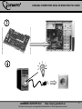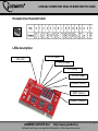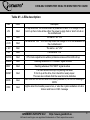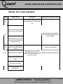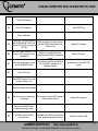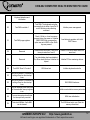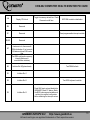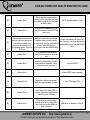
1
CHM-002 USER MANUAL HANDBUCH HANDLEIDING MANUEL DESCRIPTIF РУКОВОДСТВО ПОЛЬЗОВАТЕЛЯ КЕРІВНИЦТВО КОРИСТУВАЧА COMPUTER HEALTH MONITOR PCI CARD COMPUTER KONTROLLMONITOR FÜR DEN PCI-STECKPLATZ DIAGNOSTISCHE PCI KAART L'ORDINATEUR CONTRÔLE DE LA CARTE PCI ДИАГНОСТИЧЕСКАЯ PCI-КАРТА ДЛЯ МАТЕРИНСКОЙ ПЛАТЫ КОМПЬЮТЕРА ДІАГНОСТИЧНА PCI-КАРТА ДЛЯ МАТЕРИНСЬКОЇ ПЛАТИ КОМП'ЮТЕРА CHM-002 COMPUTER HEALTH MONITOR PCI CARD Features Designed for PCI slot of any motherboard Shows power supply unit status Indicates status of all interfaces and ports Error codes on the LED display help to pinpoint the assembly problems Specifications BIOS version supported: PHOENIX v.4.01...6.0; AMI v.6.24; AWARD v.4.5 Indicators: 8 color LEDs and 2-digit LED display PCI bus version supported: 3.3 V 32/64 bit Dimensions: 80 x 58 x 10.5 mm Net weight: 25 g GEMBIRD EUROPE B.V. http://www.gembird.eu All brands and logos are registered trademarks of their respective owners 2 CHM-002 COMPUTER HEALTH MONITOR PCI CARD GEMBIRD EUROPE B.V. http://www.gembird.eu All brands and logos are registered trademarks of their respective owners 3 CHM-002 COMPUTER HEALTH MONITOR PCI CARD GEMBIRD EUROPE B.V. http://www.gembird.eu All brands and logos are registered trademarks of their respective owners 4 CHM-002 COMPUTER HEALTH MONITOR PCI CARD GEMBIRD EUROPE B.V. http://www.gembird.eu All brands and logos are registered trademarks of their respective owners 5 CHM-002 COMPUTER HEALTH MONITOR PCI CARD GEMBIRD EUROPE B.V. http://www.gembird.eu All brands and logos are registered trademarks of their respective owners 6 CHM-002 COMPUTER HEALTH MONITOR PCI CARD Hexadecimal character table LEDs description -12V (red) +12 V (Red) +3,3 V (Red) +5V (Red) CLOCK (Red) FRAME (Green) IRDY (Green) RESET (Green) GEMBIRD EUROPE B.V. http://www.gembird.eu All brands and logos are registered trademarks of their respective owners 7 CHM-002 COMPUTER HEALTH MONITOR PCI CARD Table #1 - LEDs description LED Color Description Lit up whenever the motherboard is powered on with +5V voltage. If it is not lit up then it should be either the power supply fault or short circuit on the motherboard +5V Red -5V Red The same as "+5V” +3.3V Red The same as "+5V”. It is not lit up when the voltage 3.3V is not available on the motherboard +12V Red The same as "+5V” -12V Red CLOCK Red CPU clock adjustment is without problems whenever this LED is lit up The same as "+5V” FRAME Red Flashing whenever PCI "FRAME" signal is active IRDY Red Flashing whenever PCI "IRDY" signal is active RESET Red BIOS Red OSC Red This LED should be lit up only during the reset. If it is lit up all the time, then check the reset jumper. This can also indicate that the reset circuit is defective LED that turn on and off when the board powered on, as CPU is reading to BIOS Lights when the boardis powered on, or else the crystal oscillation circuit is broken and has no OSC message GEMBIRD EUROPE B.V. http://www.gembird.eu All brands and logos are registered trademarks of their respective owners 8 CHM-002 COMPUTER HEALTH MONITOR PCI CARD Table #2 - Error codes description Code Award BIOS AMI BIOS Phoenix4.0/Tandy3000 BIOS Code copying to specific areas is done. Passing control to INT 19h boot loader next. 00 Test the following processor status flags: carry, zero, sign, overflow CPU is testing the internal registers. CPU replacement is required if this error code is displayed 01 The BIOS sets each flag, verifies they are set, then turns each flag off and verifies it is off 02 Test all CPU internal registers except SS,SP,and BP with data FF and 00 03 Disable NMI,PIE,AIE, UEI, SQWV Verification of the real mode Disable NMI, PIE, AIE, UEI, SQWV. NMI (Nonmaskable Interrupts) is disabled. Then check whether it is the soft reset or power-on Disable Nonmaskable interrupts (NMI) Disable video, parity checking, DMA Reset math co-processor Clear all page registers, CMOS shutdown byte GEMBIRD EUROPE B.V. http://www.gembird.eu All brands and logos are registered trademarks of their respective owners 9 CHM-002 COMPUTER HEALTH MONITOR PCI CARD Initialize timer 0,1, and 2, including set EISA timer to a known state Initialize DMA controllers 0 and1 Initialize interrupt controllers 0 and 1 Initialize EISA extended registers 04 RAM must be periodically refreshed to keep the memory from decaying. This refresh function is working properly 05 Keyboard controller Initialization The BIOS stack has been built. Disable the cache memory DMA initialization in progress or failure 06 Reserved Uncompress the POST code Initialize system hardware 07 Verifies CMOS is working correctly, detects bad battery Initialize CPU and CPU data area Disable shadow and execute code from the ROM 08 Primary chipset initialization CMOS checksum calculation Initialize chipset with initial POST values Get CPU type Memory presence test OEM chipset routines Clear low 64K memory GEMBIRD EUROPE B.V. http://www.gembird.eu All brands and logos are registered trademarks of their respective owners 10 CHM-002 COMPUTER HEALTH MONITOR PCI CARD Test first 64K memory 09 Cyrix CPU initialization Set IN POST flag Cache initialization 0A Initialize first 120 interrupt vectors with SPURIOUS-INT-HDLR and initialize INT 00h-1Fh according to INT-TBL CMOS checksum calculation is done. Initialize CMOS status register with date and time Initialize CPU registers 0B Test CMOS RAM checksum, if it is wrong or INS key pressed, then load defaults The CMOS status register is initialized. Perform the required initialization before the keyboard BAT command is issued Enable CPU cache ОС Detect type of keyboard controller and set NUMLOCK status The keyboard controller input buffer is free. Issue BAT command to the keyboard controller Initialize cache to the initial POST values 0D Detect CPU clock The keyboard controller BAT command result has been verified. Initialize I/O component Initialization after BAT command test is done. Keyboard command is issued Initialize the local bus IDE Read CMOS location 14h to find out type of video in use Detect and initialize video adapter 0E Test video memory, display signon message Setup shadow RAM. Enable shadow according to setup 0F Test DMA controller 0; BIOS checksum test GEMBIRD EUROPE B.V. http://www.gembird.eu All brands and logos are registered trademarks of their respective owners 11 CHM-002 COMPUTER HEALTH MONITOR PCI CARD Keyboard detection and initialization Test DMA controller 1 Test DMA. The keyboard controller command byte is written. Issue Pin 23 and 24 blocking and unblocking command Initialize power management 11 Test DMA page registers Check if <End> or <Ins> keys were pressed during the power-on. Initialize CMOS RAM if the corresponding option was set in BIOS or the <End> key was pressed Load alternate registers with initial POST values 12 Reserved Disable DMA controllers 1 and 2 and interrupt controllers 1 and 2 Restore CPU control word during the warm boot 13 Reserved The video display has been disabled. Port B has been initialized. Initialize the chipset Initialize PCI bus mastering devices 14 Test 8254 Timer 0 Counter 2 8254 timer test Initialize keyboard controller 10 15 16 17 Verify 8259 channel 1 interrupts by turning off and on the interrupt lines Verify 8259 channel 2 interrupts by turning off and on the interrupt lines Turn off interrupts, then verify that the Nonmaskable Interrupt register is on BIOS ROM checksum Initialize cache before memory auto size 18 Force an interrupt and verify that the interrupt really occurred 8254 timer initialization 19 Test stuck NMI bits. Verify NMI can be cleared The 8254 timer test is over. Start the memory refresh test GEMBIRD EUROPE B.V. http://www.gembird.eu All brands and logos are registered trademarks of their respective owners 12 CHM-002 COMPUTER HEALTH MONITOR PCI CARD 1A Display CPU clock 1B Reserved 1C Reserved 1D,1E Reserved 1F If EISA non-volatile memory checksum is ok, then execute EISA initialization. If not, execute ISA tests and clear EISA mode flag. Toggle the memory refresh line. Check 15 seconds on/off time 8237 DMA controller initialization Reset programmable interrupt controller Test EISA configuration memory integrity(checksum & communication interface) 20 Initialize Slot 0(System board) 21 Initialize Slot 1 22 Initialize Slot 2 23 Initialize Slot 3 Test DRAM refresh Test 8742 keyboard controller Read 8042 input port and disable the MEGAKEY Green PC feature. Make the BIOS code segment writable and perform the required configuration before initializing the interrupt vectors GEMBIRD EUROPE B.V. http://www.gembird.eu All brands and logos are registered trademarks of their respective owners 13 CHM-002 COMPUTER HEALTH MONITOR PCI CARD 24 Initialize Slot 4 The configuration required before interrupt vector initialization has been completed. Interrupt vector initialization is about to begin 25 Initialize Slot 5 Interrupt vector initialization is done. Clear the password if the POST DIAG option is on 26 Test the protected mode, check CPU and motherboard internal memory. If any non-fatal errors occurred then display error messages, otherwise just boot the operating system. This is the final code 27 Initialize Slot 7 Any initialization required before setting the video mode will be done next 28 Initialize Slot 8 Initialization before setting the video mode has been completed. Set the monochrome and color mode 29 Initialize Slot 9 2A Initialize Slot 10 Initialize the different bus system, static, and output devices, if present 2B Initialize Slot 11 Pass control to the video ROM to perform any required configuration before the video ROM test 2C Initialize Slot 12 All necessary processing before passing control to the video ROM is done. Look for the video ROM and pass control to it Set ES segment register to 4GB Read/write input/output port of 8042 Enable A20 address line. Check A20 keyboard; ready for revolve mode, pins of memory controlling chips and the continue to get ready for initialization of corresponding circuit. See also AWARD all data, check 8042 chips on BIOS motherboard. See also AWARD BIOS Auto size DRAM Initialize POST memory manager GEMBIRD EUROPE B.V. Clear 512KB base RAM RAM failure on address line XXXX* http://www.gembird.eu All brands and logos are registered trademarks of their respective owners 14 CHM-002 COMPUTER HEALTH MONITOR PCI CARD 2D Initialize Slot 13 The video ROM has returned control to BIOS POST. Performing any required processing after the video ROM had control 2E Initialize Slot 14 Completed testing of the video ROM. If EGA/VGA controller is not found, perform display memory read/write test next RAM failure on data bits XXXX* of low byte of memory bus 2F Initialize Slot 15 EGA/VGA controller was not found. Display memory read/write test is about to start Enable cache before system BIOS shadow 30 Size base memory from 256K to 640K and extended memory above 1MB The display memory read/write test passed. Prepare retrace checking 31 Test base memory from 256K to 640K and extended memory above 1MB The display memory read/write test or retrace check are failed. Perform the alternate display memory read/write test next 32 In EISA mode test EISA memory found in the initialization slots The alternate display memory read/write test passed. Prepare alternate display retrace checking 33 Reserved 34 Reserved 35 Reserved 36 Reserved Test CPU bus clock frequency Initialize Phoenix dispatch manager Video display check is over. Set the display mode GEMBIRD EUROPE B.V. Warm start and shut down http://www.gembird.eu All brands and logos are registered trademarks of their respective owners 15 CHM-002 COMPUTER HEALTH MONITOR PCI CARD 37 Reserved Display mode is set. Display the power on message 38 Reserved Initialize the bus input, IPL, general devices, if present 39 Reserved Display bus initialization error messages ЗА Reserved The new cursor position has been read and saved. Displaying the Hit <DEL> message next ЗВ Reserved The Hit <DEL> message is displayed. The protected mode memory test is about to start ЗС Setup enabled Advanced configuration of chipset registers 3D Detect if mouse is present, initialize mouse, install interrupt vectors Load alternate registers with CMOS values ЗЕ Initialize cache controller 3F Reserved 40 Display virus protection disable or enable option 41 Initialize floppy disk drive controller 42 Initialize hard drive controller Shadow system BIOS ROM Auto size cache Prepare the descriptor tables next Initialize extended memory for RomPilot The descriptor tables are prepared. Enter protected mode for the memory test GEMBIRD EUROPE B.V. Initialize interrupt vectors http://www.gembird.eu All brands and logos are registered trademarks of their respective owners 16 CHM-002 COMPUTER HEALTH MONITOR PCI CARD 43 Detect and initialize serial & parallel ports and game port Entered into protected mode. Enable interrupts for diagnostics mode 44 Reserved Interrupt enabled if the diagnostics option is set. Initialize data to check memory wraparound at 0:0 next 45 Detect and initialize math coprocessor Data initialized. Check memory wraparound at 0:0 and find the total system memory size next POST device initialization 46 Reserved The memory wraparound test is done. Memory size calculation has been done. Writing patterns to test memory Check ROM copyright notice 47 Reserved The memory pattern has been written to extended memory. Writing patterns to the base 640KB memory Initialize 120 support 48 Reserved Patterns written in the base memory. Determine the size of memory below 1 MB Check video configuration against CMOS 49 Reserved The memory size below 1MB has been found and verified. Determine the size of memory above 1MB Initialize PCI bus and devices 4A Reserved 4B Reserved Initialize all video adapters The memory size above 1 MB has been found and verified. Check soft reset and clear the memory below 1 MB for the soft reset. If this is a power on situation, go to checkpoint 4E GEMBIRD EUROPE B.V. Quiet boot start (optional) http://www.gembird.eu All brands and logos are registered trademarks of their respective owners 17 CHM-002 COMPUTER HEALTH MONITOR PCI CARD 4C Reserved The memory below 1MB has been cleared via a soft reset. Clear the memory above 1MB 4D Reserved The memory above 1MB has been cleared via a soft reset. Save the memory size. Go to checkpoint 52 4E Reboot under manufacturing mode. Otherwise display messages and enter setup The memory test is started but not as the result of a soft reset. Display the first 64KB memory size Display BIOS copyright notice 4F Ask security password (optional) The memory size has been displayed. Perform the sequential and random memory test Initialize multi-boot 50 Write all CMOS values back to RAM and clear The memory below 1MB has been tested and initialized. Adjusting the displayed memory size for relocation and shadowing Display CPU type and speed 51 The memory size display has been Enable parity checker, enable NMI, adjusted for relocation and shadowing. enable cache before boot Test the memory above 1MB 52 Initialize option ROMs from C8000h to EFFFFh (or if FS can enabled then to F7FFFh) The memory above 1MB has been tested and initialized. Save the memory size information 53 Initialize time value in 0000:0040h BIOS area The memory size information and the CPU registers are saved. Enter real mode 54 Shutdown has been successful. CPU is in the real mode. Disable the gate A20 line, parity, and the NMI 55 Shadow video BIOS ROM Initialize EISA board Test keyboard Set key click if enabled Enable USB devices GEMBIRD EUROPE B.V. http://www.gembird.eu All brands and logos are registered trademarks of their respective owners 18 CHM-002 COMPUTER HEALTH MONITOR PCI CARD 57 The A20 address line, parity, and the NMI are disabled. Adjust the memory size depending on relocation and shadowing 58 The memory size has been adjusted for relocation and shadowing. Remove the Hit <DEL> message from the screen Test for unexpected interrupts 59 The Hit <DEL> message has been removed. The <WAIT…> message is displayed. Start the DMA and interrupt controller test Initialize POST display service 5A Display prompt: "Press F2 to enter SETUP” 5B Disable CPU cache 5C Test RAM between 512 and 640KB 60 Setup virus protection (boot sector protection) functionality according to the setup setting 61 Try to turn on level 2 cache (if L2 cache is already turned on in post 3D, then this part will be skipped) The DMA page register test passed. Perform the DMA controller 1 base register test Test extended memory Set the boot up speed according to setup setting Last chance for chipset initialization Last chance for power management initialization (Green BIOS only) GEMBIRD EUROPE B.V. http://www.gembird.eu All brands and logos are registered trademarks of their respective owners 19 CHM-002 COMPUTER HEALTH MONITOR PCI CARD Show the system configuration table 62 Setup NUMLOCK status according to setup values DMA controller 1 base register test passed. Perform the DMA controller 2 base register test Test extended memory address lines Program the NUMLOCK, typematic rate & typematic speed according to setup setting 63 If there are any changes in the hardware configuration, update ESCD information (PnP BIOS only) Clear memory that has been used Boot system via INT 19h 64 Jump to UserPatch1 65 The DMA controller 2 base register test passed. Program DMA controllers 1 and 2 66 Completed programming DMA controllers 1 and 2. Initialize 8259 interrupt controller Configure advanced cache registers 67 Completed 8259 interrupt controller initialization Initialize muti-processor APIC 68 Enable external and CPU caches GEMBIRD EUROPE B.V. http://www.gembird.eu All brands and logos are registered trademarks of their respective owners 20 CHM-002 COMPUTER HEALTH MONITOR PCI CARD 69 Setup system management mode (SMM) area 6A Display external L2 cache size 6B Load custom defaults (optional) 6C Display shadow area message 6E Display possible high address for UMB recovery 70 Display error message 72 Check for configuration errors 76 Check for keyboard errors 7C Setup hardware interrupt vectors 7D Initialize intelligent system monitoring 7E Initialize coprocessor if present 7F Extended NMI source enabling is in progress 80 The keyboard test has been started. Clear the output buffer and check for stuck keys. Issue the keyboard reset command GEMBIRD EUROPE B.V. Disable onboard super I/O ports and IRQs http://www.gembird.eu All brands and logos are registered trademarks of their respective owners 21 CHM-002 COMPUTER HEALTH MONITOR PCI CARD 81 A keyboard reset error or stuck key was found. Issue the keyboard controller interface test command Late POST device initialization 82 The keyboard controller interface test has been completed. Write the command byte and initialize the circular buffer Detect and install external RS232 ports 83 The command byte has been written and global data initialization has been completed. Check for a locked key Configure non-MCD IDE controllers 84 Locked key checking is over. Check for a memory size mismatch with CMOS Detect and install external parallel ports RAM data 85 The memory size check is done. Display any non-fatal error and check for a password or bypass WINBIOS setup Initialize PC-compatible PnP ISA devices 86 The password has been checked. Perform any required programming before WINBIOS setup Re-initialize onboard I/O ports 87 The programming before WINBIOS setup has been completed. Uncompress the WINBIOS setup code and execute AMIBIOS setup or WINBIOS setup utility Configure motherboard configurable devices (optional) 88 Return from WINBIOS setup and clear the screen. Perform any necessary programming after WINBIOS setup Initialize BIOS data area GEMBIRD EUROPE B.V. http://www.gembird.eu All brands and logos are registered trademarks of their respective owners 22 CHM-002 COMPUTER HEALTH MONITOR PCI CARD 89 The programming after WINBIOS setup has been completed. Display the power on screen message 8A Enable Nonmaskable Interrupts (NMIs) Initialize extended BIOS data area 8B The first screen message has been displayed. The <WAIT…> message is displayed. Perform PS/2 mouse check and extended BIOS data area allocation check Test and initialize PS/2 mouse 8C Program the WINBIOS setup options Initialize floppy controller 8D The WINBIOS setup options are programmed. Reset the hard disk controller 8E The hard disk controller has been reset. Configure the floppy drive controller 8F Determine number of ATA drivers (optional) 90 Initialize hard disk controllers 91 The floppy drive controller has been configured. Configure the hard disk drive controller Initialize local bus hard disk controllers 92 Jump to UserPatch2 93 Build MPTABLE for muti-processor boards GEMBIRD EUROPE B.V. http://www.gembird.eu All brands and logos are registered trademarks of their respective owners 23 CHM-002 COMPUTER HEALTH MONITOR PCI CARD 95 Initialize bus adaptor ROMs from C8000h to D8000h Install CD-ROM for boot 96 Initialization before passing control to the adaptor ROM atC800h Clear huge ES segment register 97 Initialization before the C800h adaptor ROM gains control has been completed. The adaptor ROM check Fix up multi-processor table 98 The adaptor ROM has now returned control to BIOS POST Search for optional ROMs. One long, two short beeps on checksum failure 99 Perform the required initialization after the optional ROM test has been completed. Configure the timer data area and printer base address Check for SMART drive (optional) 9A Set the timer and printer base addresses. Set the RS-232 base address Shadow option ROMs 9B The setting of RS-232 base address has been completed. Perform the required initialization before the coprocessor test 9C The initialization before the coprocessor test is over. Initialize the coprocessor test Setup power management 9D Coprocessor initialized. Perform the required initialization after the coprocessor test Initialize security engine (optional) GEMBIRD EUROPE B.V. http://www.gembird.eu All brands and logos are registered trademarks of their respective owners 24 CHM-002 COMPUTER HEALTH MONITOR PCI CARD 9E Initialization after the coprocessor test has been completed. Check the extended keyboard, keyboard ID, and NUMLOCK keys. Issue the keyboard ID command Enable hardware interrupts 9F Determine number of ATA and SCSI drives АО Set time of day Al Check key lock A2 Display any non-fatal error A3 The non-fatal error display has been completed. Set the keyboard typematic rate A4 The keyboard typematic rate is set. Program the memory wait states A5 Memory wait state programming is over. Clear the screen and enable parity and the NMI A7 NMI and parity are enabled. Perform the required initialization before passing control to the adaptor ROM at E000 A8 Initialization before passing control to the adaptor ROM at E000h is completed. Pass control to the adaptor ROM at E000h GEMBIRD EUROPE B.V. Initialize typematic rate Remove the F2 prompt from the screen http://www.gembird.eu All brands and logos are registered trademarks of their respective owners 25 CHM-002 COMPUTER HEALTH MONITOR PCI CARD A9 Return control from adaptor ROM at E000H. Performing the required initialization AA Initialization has been completed. Display the system configuration AB Uncompress the DMI data and execute DMI POST initialization Scan for F2 key stroke AC Enter SETUP AE Clear boot flag ВО Interrupt occurs in protected mode B1 If NMI occurs, then display: "Press F1 to disable NMI, F2 reboot" The system configuration is displayed Check for errors Inform RomPilot about the end of POST B2 POST done-prepare to boot operating system B4 One short beep before boot B5 Terminate quiet boot (optional) B6 Check password (optional) B7 Initialize ACPI BIOS GEMBIRD EUROPE B.V. http://www.gembird.eu All brands and logos are registered trademarks of their respective owners 26 CHM-002 COMPUTER HEALTH MONITOR PCI CARD B9 Prepare boot ВА Initialize SMBIOS ВВ Initialize PnP option ROMs ВС Clear parity checkers BD Display multi-boot menu BE BF СО Program chipset registers with power-on BIOS defaults Program the rest of the chipset's registers according to the setup values If auto configuration is enabled, program the chipset with the predefined values from the MODBIN.exe auto table Turn OEM specific cache shadow off Clear screen (optional) Check virus and backup reminders Try to boot with INT 19 Initialize standard devices with default values: DMA controller (8237); Programmable interrupt controller (8259); Programmable interval timer (8254); RTC chip C1 OEM specific-Test to determine the size of on-board memory C2 Initialize POST Error Manager (PEM) Initialize error logging GEMBIRD EUROPE B.V. http://www.gembird.eu All brands and logos are registered trademarks of their respective owners 27 CHM-002 COMPUTER HEALTH MONITOR PCI CARD СЗ Test the first 256K DRAM. Expand the compressed codes into temporary DRAM area including the compressed system BIOS & Option ROMs C4 Initialize error display function Initialize system error handler C5 OEM specific-Early shadow enable for fast boot PnP dual CMOS (optional) C6 External cache size detection Initialize note dock (optional) C7 Initialize note dock (continued) C8 Force check (optional) C9 Extended checksum (optional) CA Redirect INT 15h to enable remote keyboard CB Redirect INT 13h to memory devices such as ROM, AM, PCMCIA, and serial disk CC Redirect INT 10h to enable remote serial video CD Re-map I/O and memory for PCMCIA CE Initialize digitizer and display message GEMBIRD EUROPE B.V. http://www.gembird.eu All brands and logos are registered trademarks of their respective owners 28 CHM-002 COMPUTER HEALTH MONITOR PCI CARD D0 The NMI is disabled. Power-on delay starts. Verification of the initialization code checksum D1 Initialize the DMA controller, perform the keyboard controller BAT test, start memory refresh, enter 4GB flat mode D2 Unknown interrupt D3 Start memory sizing D4 Return to real mode. Execute any OEM patches and set up the stack next D5 Pass control to the uncompressed code in shadow RAM at E000:0h. The initialization code is copied to segment 0 and control will be transferred to segment 0 D6 Control is in segment 0. Check if <Ctrl><Home> was pressed and verify the system BIOS checksum. If either <Ctrl><Home>was pressed or the system BIOS checksum is bad, then go to checkpoint code E0. Otherwise go to checkpoint code D7 E0 The onboard floppy controller (if available) is initialized. Start the base 512KB memory test Initialize the chipset Initialize the interrupt vector table Initialize the bridge E1 E1 setup-Page E1 GEMBIRD EUROPE B.V. http://www.gembird.eu All brands and logos are registered trademarks of their respective owners 29 CHM-002 COMPUTER HEALTH MONITOR PCI CARD E2 E2 setup-Page E2 E3 E3 setup-Page E3 Initialize system timer E4 E4 setup-Page E4 Initialize system I/O E5 E5 setup-Page E5 Check force recovery boot E6 E6 setup-Page E6 E7 E7 setup-Page E7 Go to BIOS E8 E8 setup-Page E8 Set huge segment E9 E9 setup-Page E9 Initialize multi-processor EA EA setup-Page EA Initialize OEM special code EB EB setup-Page EB Initialize PIC and DMA EC EC setup-Page EC Initialize memory type ED ED setup-Page ED Initialize the floppy drive Initialize memory size ЕЕ ЕЕ setup-Page EE Look for a floppy diskette in drive A:. Read the first sector of the diskette Shadow boot block Initialize DMA and interrupt controllers Enable the floppy drive controller and Timer IRQs. Enable internal cache memory GEMBIRD EUROPE B.V. Initialize the CPU Checksum BIOS ROM http://www.gembird.eu All brands and logos are registered trademarks of their respective owners 30 CHM-002 COMPUTER HEALTH MONITOR PCI CARD A read error occurred while reading the floppy drive in drive A: System memory test F0 Search for AMIBOOT.ROM file in the root directory Initialize interrupt vectors F1 AMIBOOT.ROM file is not in the root directory Initialize Real Time Clock F2 Read and analyze the floppy diskette FAT to find the clusters occupied by file AMIBOOT.ROM Initialize video F3 Read AMIBOOT.ROM file, cluster by cluster Initialize System Management Manager F4 AMIBOOT.ROM file has wrong size Produce one beep F5 Disable internal cache memory. Clear huge segment EF EF setup-Page EF F6 Boot to Mini DOS F7 Boot to Full DOS FB Detect the type of flash ROM FC Erase the flash ROM FD Program the flash ROM FF INT 19H boot attempt. The motherboar has been tested to be ok Flash ROM programming has been successful. Restart the system BIOS GEMBIRD EUROPE B.V. http://www.gembird.eu All brands and logos are registered trademarks of their respective owners 31 CHM-002 COMPUTER HEALTH MONITOR PCI CARD Table #3 - Buzzer beep codes description AMI BIOS beep codes (fatal errors) Beep code 1 beep 2 beeps 3 beeps 4 beeps 5 beeps 6 beeps 7 beeps 8 beeps 9 beeps 10 beeps 11 beeps Description DRAM failed Parity check error in the first 64K DRAM Basic 64K RAM defective System timer failure Processor failure Keyboard controller gate circuit A20 failure Processor virtual mode exception occurs Display memory read/write test failure ROM BIOS checksum (32KB at F800:0) failed CMOS shutdown register read/write error Cache memory error AMI BIOS beep codes (non-fatal errors) Beep code Description 2 short POST failure - some hardware tests failed 1 long 2 short An error in the video BIOS ROM or a horizontal retrace failure 1 long 3 short Conventional/Extended memory failure 1 long 8 short Display/Retrace test failed GEMBIRD EUROPE B.V. http://www.gembird.eu All brands and logos are registered trademarks of their respective owners 32 CHM-002 COMPUTER HEALTH MONITOR PCI CARD AWARD BIOS beep codes Beep code Description 1 short System is normal 2 short Any non-fatal error, enter BIOS SETUP 1 long 1 short RAM or the motherboard error 1 long 2 short Video Error, cannot initialize screen to display any information 1 long 3 short Keyboard controller error 1 long 9 short Flash RAM/EPROM error (BIOS IC error) Long beep Memory bank is not plugged well or broken PHOENIX BIOS beep codes Beep code Description 1-1-1-3 Verify real mode 1-1-2-1 Get CPU type 1-1-2-3 Initialize system hardware 1-1-3-1 Initialize chipset registers with initial POST values 1-1-3-2 Set in POST flag 1-1-3-3 Initialize CPU registers 1-1-4-1 Initialize cache to initial POST values 1-1-4-3 Initialize I/O 1-2-1-1 Initialize power management 1-2-1-2 Load alternate registers with initial POST values 1-2-1-3 Jump to UserPatch0 1-2-2-1 Initialize keyboard controller 1-2-2-3 BIOS ROM checksum GEMBIRD EUROPE B.V. http://www.gembird.eu All brands and logos are registered trademarks of their respective owners 33 CHM-002 COMPUTER HEALTH MONITOR PCI CARD 1-2-3-1 1-2-3-3 1-2-4-1 1-3-1-1 1-3-1-3 1-3-2-1 1-3-3-1 1-3-3-3 1-3-4-1 1-3-4-3 1-4-1-3 1-4-2-4 1-4-3-1 1-4-3-2 1-4-3-3 1-4-4-1 1-4-4-2 2-1-1-1 2-1-1-3 2-1-2-1 2-1-2-3 2-1-2-4 2-1-3-1 2-1-3-2 2-1-3-3 2-1-4-1 2-1-4-3 2-2-1-1 2-2-1-3 2-2-2-1 2-2-2-3 2-2-3-1 8254 timer initialization 8237 DMA controller initialization Reset programmable interrupt controller Test DRAM refresh Test 8742 keyboard controller Set ES segment to register to 4GB Auto check size of DRAM Clear 512K base DRAM Test 512K base address lines Test 512Kbase memory Test CPU bus-clock frequency Re-initialize the chipset Shadow system BIOS ROM Re-initialize the cache Auto check size of cache Configure advanced chipset registers Load alternate registers with CMOS values Set initial CPU speed Initialize interrupt vectors Initialize BIOS interrupts Check ROM copyright notice Initialize manager for PCI Options ROMs Check video configuration against CMOS Initialize PCI bus and device Initialize all video adapters in system Shadow video BIOS ROM Display copyright notice Display CPU type and speed Test keyboard Set key click if enabled Enable keyboard Test unexpected interrupts GEMBIRD EUROPE B.V. http://www.gembird.eu All brands and logos are registered trademarks of their respective owners 34 CHM-002 COMPUTER HEALTH MONITOR PCI CARD 2-2-3-3 2-2-4-1 2-3-1-1 2-3-1-3 2-3-2-1 2-3-2-3 2-3-3-1 2-3-3-3 2-3-4-1 2-3-4-3 2-4-1-1 2-4-1-3 2-4-2-1 2-4-2-3 2-4-4-1 2-4-4-3 3-1-1-1 3-1-1-3 3-1-2-1 3-1-2-3 3-1-3-1 3-1-3-3 3-1-4-1 3-2-1-1 3-2-1-2 3-2-1-3 3-2-2-1 3-2-2-3 3-2-3-1 Display prompt "Press F2 to enter SETUP" Test RAM between 512K and 640K Test expanded memory Test extended memory address lines Jump to UserPatch1 Configure advanced cache registers Enable external and CPU caches Display external cache size Display shadow message Display non-disposable segments Display error messages Check for configuration errors Test real-time-clock(RTC) Check for keyboard errors Set up hardware interrupt vectors Test coprocessor if present Disable onboard I/O ports Detect and install external RS232 ports Detect and install external parallel ports Re-initialize onboard I/O ports Initialize BIOS data area Initialize extended BIOS data area Initialize floppy controller Initialize hard-disk controller Initialize local-bus hard-disk controller Jump to UserPatch2 Disable A20 address line Clear huge ES segment register Search for optional ROMs GEMBIRD EUROPE B.V. http://www.gembird.eu All brands and logos are registered trademarks of their respective owners 35 CHM-002 COMPUTER HEALTH MONITOR PCI CARD Table #4 – How to enter the BIOS Setup BIOS type Key Prompt AMI <Del> or <Esc> Displayed Award <Del> or <Ctrl><Alt><Esc> Displayed MR <Del>or<Ctrl><Alt><Esc> None COMPAQ Press <F10> when the cursor is displayed in the top right corner of the screen None AST <Del><Alt><Esc> None Phoenix <Del><Alt><S> None Hewlett Rackard(HP) <F2> None GEMBIRD EUROPE B.V. http://www.gembird.eu All brands and logos are registered trademarks of their respective owners 36 CHM-002 COMPUTER HEALTH MONITOR PCI CARD Table #5 – Frequently asked questions Error Memory bank Memory slot CPU Failure of CHM-02 CHM-02 displays an error code Description Memory bank is bad Suggested solution Replace it and try again Some pins are oxidized or dirty Clean the pins and try again It does not match the other bank Plugged in the wrong direction Insert the right memory bank Insert it properly The slot is dirty or there is something in it Clean the slot CPU is bad Replace it (be sure it is not too hot before touching it) The jumper setup or CMOS setup of CPU is wrong Check the setup of working voltage and frequency of CPU CPU pins are dirty Clean the pins and try again CPU is not plugged well Re-insert the CPU properly Some pins are dirty Clean the pins and try again The card is plugged into the wrong slot The card is plugged in the wrong direction CHM-02 card is bad Plug again into correct slot Check the card direction and try again Replace the card and try again Motherboard error See the description of error codes (Table #2 above), take an appropriate action and then try again The motherboard shows some error code on the display Check the error message on the screen, take an appropriate action and then try again GEMBIRD EUROPE B.V. http://www.gembird.eu All brands and logos are registered trademarks of their respective owners 37 CHM-002 COMPUTER HEALTH MONITOR PCI CARD This product is tested and complies with the essential requirements of the laws of member states concerning EMC(2004/108/EC). The CE declaration can be found under www.gembird.eu Dieses Produkt wurde getestet und stimmt mit den grundlegenden Anforderungen der Richtlinie EMC(2004/108/EC) überein. Die Konformitätserklärung kann auf unserer Webseite www.gembird.de heruntergeladen werden GEMBIRD EUROPE B.V. http://www.gembird.eu All brands and logos are registered trademarks of their respective owners 38 CHM-002 COMPUTER HEALTH MONITOR PCI CARD Waste disposal: Entsorgungshinweise: Do not deposit this equipment with the household waste. Improper disposal can harm both the environment and human health. For Information about waste collection facilities for used electrical and electronic devices, please contact your city council or an authorized company for the disposal of electrical and electronic equipment. Werfen Sie dieses Gerät nicht in den Hausmüll. Unsachgemäße Entsorgung kann sowohl der Umwelt als auch der menschlichen Gesundheit schaden. Informationen zu Sammelstellen für Altgeräte erhalten Sie bei Ihrer Stadtverwaltung oder einer autorisierten Stelle für die Entsorgung von Elektro-und Elektronikgeräten. Richtlijnen m.b.t. afvalverwerking Traitement des déchets: Batterijen en accu’s dienen als kleinchemisch afval afgeleverd te worden bij toegewezen afvalverzamelpunten (zie www.afvalgids.nl). U dient ervoor te zorgen dat de batterijen/accu’s leeg zijn en dus geen stroom meer kunnen leveren. Let op, de batterijen/accu’s dienen onbeschadigd ingeleverd te worden. Ne jetez pas cet appareil dans les déchets domestiques. Un traitement inapproprié peut être dommageable à l'environnement et à la santé humain. Gooi dit product niet weg in uw vuilnisbak. Dit kan zowel het milieu als de menselijke gezondheid schade toebrengen. Informatie over het inleveren van dit product kunt u inwinnen bij uw gemeentelijke vuilnisdienst of andere geautoriseerde instelling in uw buurt. chez un centre autorisé pour le traitement des appareils électriques ou électroniques. GEMBIRD EUROPE B.V. Vous trouvez des informations sur les centres de rassemblement des appareils vieux chez l'administration municipale ou http://www.gembird.eu All brands and logos are registered trademarks of their respective owners 39 CHM-002 COMPUTER HEALTH MONITOR PCI CARD WARRANTY CONDITIONS GARANTIE BEDINGUNGEN The receipt must clearly list the date of purchase and the part number, in addition it should be printed. Keep the receipt for the entire warranty period since it is required for all warranty claims. During the warranty period the defective items will be credited, repaired or replaced at the manufacturer's expense. Work carried out under the warranty neither extends the warranty period nor starts a new warranty period. The manufacturer reserves the right to void any warranty claim for damages or defects due to misuse, abuse or external impact (falling down, impact, ingress of water, dust, contamination or break). Wearing parts (e.g. rechargeable batteries) are excluded from the warranty. Upon receipt of the RMA goods, Gembird Europe B.V. reserves the right to choose between replacement of defective goods or issuing a credit note. The credit note amount will always be calculated on the basis of the current market value of the defective products Die Garantie beträgt 24 Monate ab Verkaufsdatum an den Endverbraucher. Das Kaufdatum und der Gerätetyp sind durch eine maschinell erstellte Kaufquittung zu belegen. Bitte bewahren Sie Ihren Kaufbeleg daher für die Dauer der Garantie auf, da er Voraussetzung für eine eventuelle Reklamation ist. Innerhalb der Garantiezeit werden alle Mängel, wahlweise durch den Hersteller entweder durch Instandsetzung, Austausch mangelhafter Teile oder im Austausch, behoben. Die Ausführung der Garantieleistung bewirkt weder eine Verlängerung noch einen Neubeginn der Garantiezeit. Eine Garantieleistung entfällt für Schäden oder Mängel die durch unsachgemäße Handhabung oder durch äußere Einwirkung (Sturz, Schlag, Wasser, Staub, Verschmutzung oder Bruch) herbeigeführt wurden. Verschleißteile (z.B. Akkus) sind von der Garantie ausgenommen. Gembird Europe B.V. Wittevrouwen 56, 1358CD Almere The Netherlands www.gembird.nl/support [email protected] Tel. +31-36-5211588 GEMBIRD EUROPE B.V. GEMBIRD Deutschland GmbH Coesterweg 45, 59494 Soest Deutschland www.gembird.de/support [email protected] Tel. +49-180 5-436247 0,14 € pro Minute aus dem deutschen Festnetz. Mobilfunkpreise können abweichen http://www.gembird.eu All brands and logos are registered trademarks of their respective owners 40 CHM-002 COMPUTER HEALTH MONITOR PCI CARD GARANTIE VOORWAARDEN CONDITIONS DE GARANTIE Op de aankoopbon moeten de aankoopdatum en productomschrijving duidelijk vermeld staan. Gelieve de aankoopbon de gehele garantieperiode te bewaren, deze is ten alle tijden benodigd voor alle garantie aanspraken. Tijdens de garantieperiode zullen alle gebreken verholpen of vervangen worden door de fabrikant d.m.v. reparatie, omruiling van het defecte onderdeel of het gehele apparaat. Aanspraken tijdens de garantieperiode leiden niet tot verlenging hiervan. Garantieaanspraak vervalt bij schade of gebreken die ontstaan zijn door oneigenlijk gebruik, misbruik of invloeden van buitenaf (vallen, stoten, water, stof, vuil of breken). Slijtagegevoelige onderdelen (b.v. batterijen) zijn uitgesloten van garantie. Bij ontvangst van de RMA goederen behoudt Gembird zich het recht om te kiezen tussen vervanging van de defecte waren of het uitgeven van een kreditnota. Het bedrag van de kreditnota zal altijd gecalculeerd zijn op basis van de huidige marktprijs voor het defecte produkt. Le talon de garantie doit énumérer clairement la date d'achat et le type d'appareil. Conservez le reçu d'achat pendant toute la durée de la garantie car elle est nécessaire pour toute réclamation. Au cours de la période de garantie tous les défauts doivent être remplacé aux frais du fabricant, soit par la réparation ou la remplacement de la pièce défectueuse ou l'ensemble du produit. Les travaux effectués sous garantie ne prolongent pas la période de garantie ni ne commencent pas une nouvelle période de garantie. Le fabricant se réserve le droit d'annuler toute demande de garantie pour les dommages ou défauts dus à une mauvaise utilisation, abus ou les effets externes (chute, choc, pénétration de l'eau, la poussière, etc..). Les pièces d'usure (par exemple les piles rechargeables) sont exclus de la garantie. Dès réception de la marchandise sous garantie, le SAV de Gembird Europe BV se réserve le droit de choisir entre le remplacement des produits défectueux ou de délivrer un avoir. Le montant d’avoir sera toujours calculée sur la base de la valeur actuelle du marché des produits défectueux. Gembird Europe B.V. Wittevrouwen 56, 1358CD Almere The Netherlands www.gembird.nl/support [email protected] Tel. +31-36-5211588 € 0,15 p/m binnen Nederland Exclusief mobiele telefoonkosten GEMBIRD EUROPE B.V. Gembird Europe B.V. Wittevrouwen 56 1358CD Almere, The Netherlands www.gembird.nl/support [email protected] +33(0) 251 404849 Prix d'appel depuis telephone fixe Pays-Bas : 0.15 euro / min Prix d'appel depuis telephone mobile / autre pays - selon operateur http://www.gembird.eu All brands and logos are registered trademarks of their respective owners 41 CHM-002 COMPUTER HEALTH MONITOR PCI CARD ГАРАНТИЙНЫЙ ТАЛОН УМОВИ ГАРАНТІЙНОГО ОБСЛУГОВУВАННЯ 1. Гарантийное обслуживание предоставляется в течение срока гарантии, при наличии правильно и четко заполненного гарантийного талона, и изделия в полной комплектации. Серийный номер и модель изделия должны соответствовать указанным в гарантийном талоне. 2. Гарантийное обслуживание представляет собой бесплатное устранение всех неполадок (ремонт), или замену изделия на новое (аналогичное). 3. Гарантия не распространяется на неисправности, вызванные следующими причинами: • использование изделия не по назначению. • нарушение условий эксплуатации, хранения или перевозки изделия, которые указаны в настоящей инструкции. • подключение нестандартных или неисправных периферийных устройств, аксессуаров. • механические повреждения, попадание внутрь изделия посторонних предметов, веществ, жидкостей, насекомых. • ремонт изделия не уполномоченными на то лицами. 4. Комплектность и внешний вид изделия проверяются Покупателем при получении товара в присутствии персонала фирмы. Послепродажные претензии по укомплектованности и внешнему виду не принимаются. 1. Гарантійне обслуговування надається протягом терміну гарантії, при наявності Гарантійного талону, заповненого належним чином, та виробу в повній комплектації. 2. Гарантійне обслуговування не підтримується в разі порушення правил експлуатації, зберігання або перевезення виробу, що зазначені в інструкції по експлуатації виробу. 3. Гарантійне обслуговування скасовується у випадках: - наявності механічних пошкоджень або слідів стороннього втручання; - пошкодження викликані стихійним лихом або нещасним випадком, включаючи й блискавку, потраплянням у виріб сторонніх предметів, рідин, комах, тощо; - пошкодження викликані застосуванням або підключенням нестандартних або несправних периферійних пристроїв, аксесуарів; 4. Гарантія не поширюється на витратні матеріали та додаткові аксесуари; З гарантійними умовами згоден. Наименование изделия: ___________________________ Модель _________________________________________ Серийный номер _________________________________ Срок гарантии ___________________________________ Дата продажи «____» ___________________ 20____ года Фирма-продавец: _________________________________ Адрес и телефон фирмы-продавца: ________________________________________________ М.П. С условиями гарантии ознакомлен и согласен: Продавец: _____________ Покупатель: _____________ GEMBIRD EUROPE B.V. Підпис покупця: ____________________ ГАРАНТІЙНИЙ ТАЛОН № __________________________ Товар/модель ____________________________________ Серійний номер __________________________________ Термін гаранії ____________________________________ Дата продажу ____________________________________ Продавець (назва, телефон) _________________________________________ Печатка та підпис продавця _________________________________________ З гарантійних питань звертайтесь до сервісних центрів Gembird. Про адреси та контакти Ви можете дізнатись на сайті www.gembird.ua або по телефону 044-4510213. http://www.gembird.eu All brands and logos are registered trademarks of their respective owners 42