1
PrintFleet Optimizer
User Guide
As of June 25, 2010.
© 2010 PrintFleet Inc. All rights reserved.
© Copyright 2010 PrintFleet™ Inc. All rights reserved.
PrintFleet Optimizer User Guide.
The content of this user manual is furnished for informational use only, and is subject to change without
notice.
Except as permitted by license, no part of this publication may be reproduced or transmitted, in any
form or by any means, electronic, mechanical, recording, or otherwise, without the prior written
permission of PrintFleet Inc.
PrintFleet, PrintFleet Optimizer, PrintFleet Suite PRO, and PrintFleet Local Beacon are trademarks of
PrintFleet Inc.
Microsoft, Windows, Internet Explorer, and SQL Server are trademarks or registered trademarks of
Microsoft Corporation in the United States and other countries.
Compass Sales Solutions is a trademark or registered trademark of Compass Sales Solutions.
DocuAudit and Proposal Wizard are trademarks or registered trademarks of DocuAudit International
Inc.
TCO Optimizer is a trademark or registered trademark of Kyocera Corporation.
XOPA is a trademark or registered trademark of Xerox Corporation.
Canon is a registered trademark of Canon Inc.
Digital Gateway and e-automate are trademarks or registered trademarks of Digital Gateway Inc.
OMD, OMD Vision, NetVision, and OMD iManager are registered trademarks of OMD Corporation.
Evatic is a trademark or registered trademark of Evatic AS.
Contact PrintFleet:
PrintFleet Inc., 275 Ontario Street, Suite 301, Kingston, Ontario K7K 2X5, CANADA
Toll free: 1-866-382-8320
www.printfleet.com
Telephone: 1 (613) 549-3221
Fax: 1 (613) 549-3222
PrintFleet Optimizer
Table of Contents
Table of Contents
Chapter 1
Chapter 2
Introduction . . . . . . . . . . . . . . . . . . . . . . . . . . . . . . . . . . . . . . . . . . . . . 1
1.1
Device support . . . . . . . . . . . . . . . . . . . . . . . . . . . . . . . . . . . . . . . 1
1.2
Installation requirements . . . . . . . . . . . . . . . . . . . . . . . . . . . . . . . . 2
1.3
Obtaining software updates . . . . . . . . . . . . . . . . . . . . . . . . . . . . . . 2
1.4
Contacting Technical Support . . . . . . . . . . . . . . . . . . . . . . . . . . . . . 3
Using the Printer Data Collector Agent. . . . . . . . . . . . . . . . . . . . . . . . . 4
2.1
Obtaining the DCA software . . . . . . . . . . . . . . . . . . . . . . . . . . . . . . 5
2.2
Installing and activating the DCA . . . . . . . . . . . . . . . . . . . . . . . . . . 6
2.3
Managing the DCA service . . . . . . . . . . . . . . . . . . . . . . . . . . . . . . . 8
Installing and starting the DCA service . . . . . . . . . . . . . . . . . . . . 8
Setting up the DCA as a scheduled task. . . . . . . . . . . . . . . . . . . . 8
2.4
Configuring communication settings . . . . . . . . . . . . . . . . . . . . . . . . 9
Changing and testing the communication method and port . . . . . . 9
Using proxy settings . . . . . . . . . . . . . . . . . . . . . . . . . . . . . . . . .10
Changing the web service timeout . . . . . . . . . . . . . . . . . . . . . . .10
Enabling Intelligent Update . . . . . . . . . . . . . . . . . . . . . . . . . . . .11
Enabling a Service Bridge . . . . . . . . . . . . . . . . . . . . . . . . . . . . .11
Troubleshooting DCA communication problems. . . . . . . . . . . . . . .12
2.5
Configuring network scan settings. . . . . . . . . . . . . . . . . . . . . . . . . .13
Managing scan profiles . . . . . . . . . . . . . . . . . . . . . . . . . . . . . . .13
Specifying which devices to scan . . . . . . . . . . . . . . . . . . . . . . . .14
Enabling scanning of network and/or local devices . . . . . . . . . . . .17
Enabling broadcast scanning . . . . . . . . . . . . . . . . . . . . . . . . . . .17
Enabling Rapid Scan . . . . . . . . . . . . . . . . . . . . . . . . . . . . . . . . .17
Setting the scan and transmission interval . . . . . . . . . . . . . . . . . .18
Setting the network timeout. . . . . . . . . . . . . . . . . . . . . . . . . . . .18
Setting the Local Print Agent timeout . . . . . . . . . . . . . . . . . . . . .18
Setting the number of SNMP retries . . . . . . . . . . . . . . . . . . . . . .19
Using Focus Scans . . . . . . . . . . . . . . . . . . . . . . . . . . . . . . . . . .19
iii
PrintFleet Optimizer
Table of Contents
Storing SNMP community strings . . . . . . . . . . . . . . . . . . . . . . . . 20
Masking private data . . . . . . . . . . . . . . . . . . . . . . . . . . . . . . . . . 20
Enabling SNMP traps . . . . . . . . . . . . . . . . . . . . . . . . . . . . . . . . . 21
Disabling real time DCA status . . . . . . . . . . . . . . . . . . . . . . . . . . 21
2.6
Managing local devices with Local Print Agent . . . . . . . . . . . . . . . . . 22
2.7
Viewing queue, archive, and log files. . . . . . . . . . . . . . . . . . . . . . . . 23
Deleting old archive and log files . . . . . . . . . . . . . . . . . . . . . . . . 24
2.8
Configuring language and read/write settings. . . . . . . . . . . . . . . . . . 25
2.9
Updating the DCA software . . . . . . . . . . . . . . . . . . . . . . . . . . . . . . 26
2.10 Understanding the network load associated with the DCA . . . . . . . . . 26
Chapter 3
Using PrintFleet Optimizer . . . . . . . . . . . . . . . . . . . . . . . . . . . . . . . . . 27
3.1
Working with the interface . . . . . . . . . . . . . . . . . . . . . . . . . . . . . . . 27
Logging in to the system . . . . . . . . . . . . . . . . . . . . . . . . . . . . . . 28
Using the search function . . . . . . . . . . . . . . . . . . . . . . . . . . . . . 29
Changing your preferences . . . . . . . . . . . . . . . . . . . . . . . . . . . . 29
3.2
Working with device views . . . . . . . . . . . . . . . . . . . . . . . . . . . . . . . 30
Filtering and sorting data. . . . . . . . . . . . . . . . . . . . . . . . . . . . . . 31
Viewing new devices . . . . . . . . . . . . . . . . . . . . . . . . . . . . . . . . . 32
Working with the traffic light system . . . . . . . . . . . . . . . . . . . . . . 32
Working with the default views. . . . . . . . . . . . . . . . . . . . . . . . . . 33
Using the Technical View . . . . . . . . . . . . . . . . . . . . . . . . . . . . . . 34
Using the Supplies Order View . . . . . . . . . . . . . . . . . . . . . . . . . . 34
Using the Maps View . . . . . . . . . . . . . . . . . . . . . . . . . . . . . . . . . 36
Using the Alerts View . . . . . . . . . . . . . . . . . . . . . . . . . . . . . . . . 39
Creating custom device views . . . . . . . . . . . . . . . . . . . . . . . . . . 40
3.3
Working with the Device Detail view . . . . . . . . . . . . . . . . . . . . . . . . 41
Viewing embedded web pages . . . . . . . . . . . . . . . . . . . . . . . . . . 44
Viewing historical LCD and error information . . . . . . . . . . . . . . . . 44
Working with the Supplies tab . . . . . . . . . . . . . . . . . . . . . . . . . . 44
Working with the Meters tab . . . . . . . . . . . . . . . . . . . . . . . . . . . 44
Working with the Service tab . . . . . . . . . . . . . . . . . . . . . . . . . . . 45
Working with the Miscellaneous tab . . . . . . . . . . . . . . . . . . . . . . 46
Working with the Model tab . . . . . . . . . . . . . . . . . . . . . . . . . . . . 46
3.4
Using reports . . . . . . . . . . . . . . . . . . . . . . . . . . . . . . . . . . . . . . . . 47
Generating reports . . . . . . . . . . . . . . . . . . . . . . . . . . . . . . . . . . 47
Editing and deleting reports . . . . . . . . . . . . . . . . . . . . . . . . . . . . 50
Scheduling reports . . . . . . . . . . . . . . . . . . . . . . . . . . . . . . . . . . 51
Building Executive Reports. . . . . . . . . . . . . . . . . . . . . . . . . . . . . 52
iv
PrintFleet Optimizer
Table of Contents
Building Custom Reports . . . . . . . . . . . . . . . . . . . . . . . . . . . . . . 53
Using the Cost per Image (CPI) Calculator . . . . . . . . . . . . . . . . . . 54
3.5
Using alerts . . . . . . . . . . . . . . . . . . . . . . . . . . . . . . . . . . . . . . . . . 56
Creating new alerts . . . . . . . . . . . . . . . . . . . . . . . . . . . . . . . . . . 56
Editing alerts . . . . . . . . . . . . . . . . . . . . . . . . . . . . . . . . . . . . . . 57
Deleting alerts . . . . . . . . . . . . . . . . . . . . . . . . . . . . . . . . . . . . . 58
Managing alert layouts . . . . . . . . . . . . . . . . . . . . . . . . . . . . . . . 58
Working with alert emails . . . . . . . . . . . . . . . . . . . . . . . . . . . . . 59
3.6
Using flags . . . . . . . . . . . . . . . . . . . . . . . . . . . . . . . . . . . . . . . . . . 60
Creating flags. . . . . . . . . . . . . . . . . . . . . . . . . . . . . . . . . . . . . . 61
Closing flags . . . . . . . . . . . . . . . . . . . . . . . . . . . . . . . . . . . . . . 61
Editing flags . . . . . . . . . . . . . . . . . . . . . . . . . . . . . . . . . . . . . . . 62
3.7
Managing groups . . . . . . . . . . . . . . . . . . . . . . . . . . . . . . . . . . . . . 62
Creating, editing, and deleting groups . . . . . . . . . . . . . . . . . . . . . 62
Assigning devices to groups . . . . . . . . . . . . . . . . . . . . . . . . . . . . 64
Managing group types . . . . . . . . . . . . . . . . . . . . . . . . . . . . . . . . 65
3.8
Managing users . . . . . . . . . . . . . . . . . . . . . . . . . . . . . . . . . . . . . . 67
3.9
Managing devices . . . . . . . . . . . . . . . . . . . . . . . . . . . . . . . . . . . . . 69
Editing device information . . . . . . . . . . . . . . . . . . . . . . . . . . . . . 70
Creating custom device fields . . . . . . . . . . . . . . . . . . . . . . . . . . . 71
Viewing, editing, and exporting service history . . . . . . . . . . . . . . . 73
Marking devices as managed, unmanaged, or hidden . . . . . . . . . . 74
Exporting and importing device information . . . . . . . . . . . . . . . . . 75
Assigning CPC charges . . . . . . . . . . . . . . . . . . . . . . . . . . . . . . . 78
3.10 Virtual Meters. . . . . . . . . . . . . . . . . . . . . . . . . . . . . . . . . . . . . . . . 78
3.11 Configuring meter exports . . . . . . . . . . . . . . . . . . . . . . . . . . . . . . . 79
Transitioning from PrintFleet Optimizer 2.0 . . . . . . . . . . . . . . . . . 79
Configuring an external ERP system . . . . . . . . . . . . . . . . . . . . . . 80
Configuring meter maps . . . . . . . . . . . . . . . . . . . . . . . . . . . . . . 81
Setting up meter export schedules . . . . . . . . . . . . . . . . . . . . . . . 82
Configuring device maps (exceptions only) . . . . . . . . . . . . . . . . . 84
Testing and troubleshooting . . . . . . . . . . . . . . . . . . . . . . . . . . . . 84
3.12 Managing DCA installations . . . . . . . . . . . . . . . . . . . . . . . . . . . . . . 88
Generating PIN Codes for DCA version 4.0 or greater . . . . . . . . . . 88
Generating Manual Keys for DCA version 3.x . . . . . . . . . . . . . . . . 89
Generating Automatic Keys for DCA version 3.x (pregenerated) . . . 90
Managing DCAs . . . . . . . . . . . . . . . . . . . . . . . . . . . . . . . . . . . . 90
v
PrintFleet Optimizer
Introduction
Chapter 1
Introduction
Welcome to PrintFleet Optimizer—a remote print management
system designed to help owners, sales representatives, service
technicians, and administrative personnel grow and streamline their
business.
This is guide designed to assist dealers with the following:
Using the Printer Data Collector Agent
This chapter discusses:
1.1
•
Device support
•
Installation requirements
•
Obtaining software updates
•
Contacting Technical Support
Device support
PrintFleet strives to develop vendor-neutral software products, and
to support as many models of printers, copiers, fax machines, and
multifunction peripherals as possible. However, our products do not
support all models available in the market. PrintFleet is continuously
adding model support into our software products.
Supported models are not all supported to the same extent. For
example, one model may be supported for all available data types,
while another may only be supported for specific data types, such as
device description and life page count.
PrintFleet software products collect information from networked
imaging devices. Stand alone devices are not supported. Locally
connected devices can be partially supported by using the PrintFleet
Local Print Agent add-on application.
1
PrintFleet Optimizer
Introduction
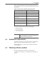
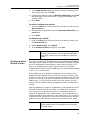
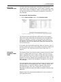
Table 1 lists the data types that the Printer Data Collector Agent
(DCA) attempts to collect from networked imaging devices during a
network scan.
Table 1: Types of data collected by the Printer DCA
IP address
toner cartridge serial number
device description
maintenance kit levels
serial number
non-toner supply levels
meter reads (multiple)
asset number
monochrome or color
identification
location
LCD reading
MAC address
device status
manufacturer
error codes
firmware
toner levels
miscellaneous (machine
specific)
The Local Print Agent collects the following data types:
•
Device driver name
•
Device manufacturer
•
Communications port
Note
1.2
Additional data collection (such as counts, toner
level, and supplies) from local devices depends on
the data the device itself supports.
Installation requirements
Installation requirements for the DCA are listed in “Data Collector
Agent Checklist and Installation Requirements” on page 94.
All PFE Enterprise server components are installed by PrintFleet
Technical support.
1.3
Obtaining software updates
New software releases are available on a periodic basis.
To update the DCA software, see “Updating the DCA software” on
page 26.
2
PrintFleet Optimizer
Introduction
Contact your PrintFleet distributor for information on obtaining
software updates, or to provide suggestions for software
enhancements.
1.4
Contacting Technical Support
For technical support, contact your PrintFleet distributor.
3
PrintFleet Optimizer
Using the Printer Data Collector Agent
Chapter 2
Using the Printer Data Collector
Agent
The Printer Data Collector Agent (DCA) is a software application
that collects information from supported printers, copiers, fax
machines, and multifunction peripherals on a network, and
transmits the data back to a PrintFleet Enterprise server.
Data from locally connected devices can also be collected, provided
that the Local Print Agent application is installed on each computer
connected to a local printer.
For more detailed information on device support, and for a list of
data types that are collected, see “Device support” on page 1.
4
PrintFleet Optimizer
Using the Printer Data Collector Agent
This chapter discusses:
•
Obtaining the DCA software
•
Managing the DCA service
•
Configuring communication settings
•
Configuring network scan settings
•
Managing local devices with Local Print Agent
•
Viewing queue, archive, and log files
•
Configuring language and read/write settings
•
Updating the DCA software
•
Understanding the network load associated with the DCA
Note
2.1
If you have also purchased PrintFleet Suite Pro,
you will have helpful built-in features for
configuring and optimizing your DCA settings
(consult the PrintFleet Suite Pro User Guide for
further details):
•
Use PrintFleet Auditor to perform network
scans with various settings until you are happy
with the scan performance and results—these
settings can then be replicated in the DCA.
•
Use PrintFleet Asset Tracker to embed missing
data to the non-volatile memory of imaging
devices, including serial number, asset number,
location, and department.
Obtaining the DCA software
You can obtain the DCA installation file from your distributor. The
distributor chooses their own method of distributing the file, such
as: email, CD, or USB key.
You may be provided access to the DCA installation file through
PrintFleet Optimizer. Instructions for obtaining the DCA installation
using PrintFleet Optimizer are provided below.
Alternately, PrintFleet Optimizer can provide access to the DCA
installation file. Instructions for obtaining the DCA installation file
using PrintFleet Optimizer are provided below.
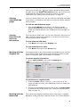
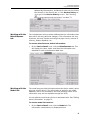
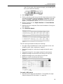
To obtain the DCA installation file from PrintFleet Optimizer:
1. On the Administration menu click DCA Install.
2. Do one of the following:
•
In DCA 4.x tab, click the Printer DCA 4.x.x.x.msi link and
save the file to the computer.
•
In DCA 3.x tab, click the DCA_Install.msi link and save the
file to the computer.
5
PrintFleet Optimizer
Using the Printer Data Collector Agent
The DCA Install screen displays the most recent release notes and
other software prerequisites.
2.2
Installing and activating the DCA
The DCA should be installed on an existing networked server to
collect and transmit device data. If no server is available, the DCA
can be installed on a single networked computer that will remain
powered on 24 hours a day, 7 days a week.
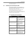
For DCA installation requirements, see “Data Collector Agent
Checklist and Installation Requirements” on page 94.
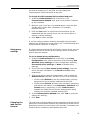
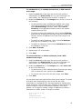
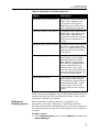
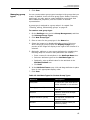
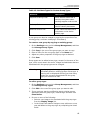
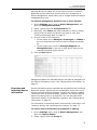
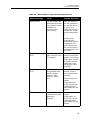
Prior to installing the DCA, you should obtain the information in the
following table from the network administrator at the location. This
will allow you to properly configure the DCA.
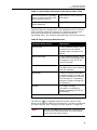
Table 2: Information to Gather from the Network
Administrator Prior to a DCA Installation
Find out...
Solution
if there are local devices you
want to monitor.
Once the DCA is installed, you
will have to enable local data
collection and install Local Print
Agent on applicable computers.
See “Managing local devices
with Local Print Agent” on
page 22.
how many total printing
devices reside on the network
and how large the network is.
An additional DCA should be
installed on a separate
computer for each 10,000
imaging devices on the
network or 100,000 IP
addresses.
if the network uses multiple
subnets.
If so, take note of the subnets
and IP ranges to ensure they
are all included in the network
scan range.
if the network uses a Virtual
Private Network (VPN) or has
Wide Area Network (WAN)
links.
If so, the network timeout for
the DCA should be increased to
500–1000 milliseconds.
if the company has multiple
offices they want monitored.
If so, a single DCA may be used
if the networks are connected
via a VPN, however, it is
recommended that a DCA is
installed at each location.
6
PrintFleet Optimizer
Using the Printer Data Collector Agent
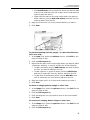
The DCA has an easy to use installation wizard that in many cases
will configure the settings you need to collect data from networked
printing devices. To collect data from local devices, and to further
configure settings, you will need to open the DCA application after
installation.
To install and activate the DCA:
1. Double-click the filename Printer DCA 4.x.x.x.msi
installation file.
2. The Printer DCA Installation Wizard is launched. Click Next to
continue.
3. Read through the End-User License Agreement, check I accept
the terms in the License Agreement and select Next to
continue. If you do not accept the terms, the installation process
will not continue.
4. In the Destination Folder screen, either leave the default folder
displayed, or enter a new destination folder. Click Next to
continue.
5. In the Ready to Install Printer DCA screen, click Install to begin
installation or click Cancel to exit.
6. In the Completed the Printer DCA Installation Wizard, leave
checked or uncheck Launch Printer DCA after installation
and select Finish.
7. After the Printer DCA is launched, in the second End-User
License Agreement, select Accept to continue or select Decline
to not continue.
8. In the Welcome to the Printer DCA-Setup Wizard, select the
language from the drop down list and select Next.
9. In the Printer DCA Activation screen, enter the following:
•
Enter the server information for the server that the DCA will
be sending information to in the Server box.
•
Enter the PIN code in the PIN Code box.
•
Optionally, if the location is using a proxy server that you
want to configure at this point (you will also be able to do so
after installation), click Show Proxy Configuration. See
“Using proxy settings” on page 10.
•
Click Next.
Note
You can continue past this step without entering a
PIN code, but data will not be transmitted to the
server until activation is complete.
10. In the Scan Settings screen, you will be shown a list of
preconfigured IP ranges that will be added to your default DCA
network scan. This can be changed after installation is complete
if necessary. Click Next.
11. In the Intelligent Updates screen, you will be given the option to
disable Intelligent Updates. It is recommended that Allow
Intelligent Updates remains selected unless there is a strong
7
PrintFleet Optimizer
Using the Printer Data Collector Agent
reason to turn it off. Click Next. See “Enabling Intelligent
Update” on page 11.
12. In the Setup is Complete screen, by default, the Open the Data
Collector Agent Interface and Start the Data Collector
Agent Service are both selected. Optionally, you can turn off
one or both of these options. Click Finish.
At some point over the life of the DCA installation, you may need to
reactivate it, for example, if you were given an activation code with
an expiry date, or if you need to redirect the DCA to a new server.
You can enter a new activation code from an existing DCA
installation.
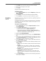
To reactivate the DCA:
1. On the Tools menu, click Reactivate DCA.
2. If you are redirecting the DCA to a new server and/or port, enter
the new information in the Server box.
3. Enter the new activation code in the PIN Code box.
4. Click Activate.
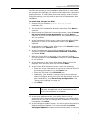
2.3
Managing the DCA service
The DCA runs as a Windows service by default. Alternatively, the
DCA can be set up as scheduled task.
Installing and
starting the DCA
service
The DCA service can be installed, uninstalled, started, or stopped at
any time. You may need to reinstall the DCA service if you have
previously been running the DCA as a scheduled task, or if the DCA
service was uninstalled for any other reason. If you have been
running the DCA as a scheduled task, delete the scheduled task
before reinstalling the DCA service.
To install, uninstall, start, or stop the DCA service:
•
Setting up the
DCA as a
scheduled task
Under the Status tab of the DCA, in the Service area, beside
DCA Status, click the Options button, and select the operation
you want to perform.
To set up the DCA as a scheduled task instead of a service, you
must first uninstall the DCA service, and then create the DCA
scheduled task.
To uninstall the DCA service:
1. For DCA 3.x, on the File menu of the DCA, click Advanced
Options.
2. In the Service Control (Main) area, click Uninstall.
8
PrintFleet Optimizer
Using the Printer Data Collector Agent
3. Click Save and Close.
4. For DCA 4.x, in the Status tab, click Options and select
Uninstall.
5. Click Save and Close.
To create a scheduled task for the DCA:
1. Click Start, click Control Panel, and then double-click
Scheduled Tasks.
2. On the File menu, point to New, and then click Scheduled
Task.
3. Replace New Task with a recognizable name for the task, such
as DCATask, and click anywhere away from the new task icon to
save the name.
4. Double-click your newly created task.
5. In the Task tab, type the following in the Run box, including the
quotations:
“C:\Program Files\Printer DCA\PrinterDCA.Service.exe”
commandline
6. Click the Schedule tab.
7. In the Schedule Task list, select an interval that you want the
task to run.
8. In the Start Time box, type or select the time of day that you
want the task to run.
9. Click Apply.
10. Type in your network login name in the Run as box.
11. Type in your network password in the Password box, and
repeat in the Confirm Password box.
12. Click OK.
2.4
Configuring communication settings
During the DCA installation, the DCA will attempt to establish basic
communication with the central server using either HTTPS (default)
or HTTP (secondary). Proxy settings can also be configured during
installation, or at any time afterwards. If communication with the
server is successful during installation, it is not necessary to change
the communication method, port, or proxy settings.
Changing and
testing the
communication
method and port
There are two methods the DCA can use to send information to the
central server: HTTPS and HTTP. During installation, the DCA will
attempt to establish communication with the central server, first,
with HTTPS (port 443), and if that fails, HTTP (port 80). If you don’t
use the default port for your chosen method of communication, you
9
PrintFleet Optimizer
Using the Printer Data Collector Agent
will need to change this in the DCA. You can change the
communication method and port at any time.
To change the DCA communication method and port:
1. Under the Communication tab of the DCA, in the
Communication Method area, type in the protocol, followed
by the hostname.
2. Optional--only if you use a non-standard port--enter the port
number after a colon after a hostname. For example,
printfleet.com:84.
3. Click the Test button to verify that communication can be
established with the central server. You will receive either a
success or failure message.
4. Click Save to retain changes.
If you are having problems obtaining successful communication
between the DCA and the central server, see “Troubleshooting DCA
communication problems” on page 12.
Using proxy
settings
If a network being scanned with a DCA uses a proxy server, you can
configure the DCA to use the proxy settings, which will allow the
DCA to scan the network.
To use a manual proxy configuration:
1. Under the Communication tab of the DCA, in the Proxy
Configuration area, click to select one of the following: Use
Windows proxy settings (no other configuration required),
Use custom proxy settings, or None (to disable proxy
settings).
2. If you have selected Use custom proxy settings, enter the
server and port information in the Server and Port boxes,
respectively.
3. If the proxy server requires authentication, click to select the
Authentication check box, and then do one of the following:
•
Click to select Default to use the authentication currently
being used on the computer installed with the DCA.
•
Click to select Custom, and then enter username, password,
and domain information in the Username, Password, and
Domain boxes, respectively, or click Load Current to
populate the fields with the current authentication being
used by the computer installed with the DCA.
4. In the Communication Method area, click Test to verify the
settings are working.
5. Click Save.
Changing the
web service
timeout
The web service timeout determines the maximum time that will be
allowed for communication between the DCA and the central server.
By default, the web service timeout is 30 seconds; if necessary, the
timeout can be increased or decreased at any time.
10
PrintFleet Optimizer
Using the Printer Data Collector Agent
To change the web service timeout:
1. Under the Communication tab, in the Communication
Settings area, enter or select the desired timeout in the Web
Service Timeout box.
2. Click Save.
The Web Service Discovery Timeout controls the initial connection
to the server and the auto-selection of http/https.
Enabling
Intelligent
Update
When Intelligent Update is enabled, the DCA can be remotely
updated by your PrintFleet administrator. This is important to
ensure you are always able to collect the highest quantity and
quality of information available.
To enable Intelligent Update:
1. Under the Communication tab, in the Communication
Settings area, click to select the Enable Intelligent Update
check box.
2. Click Save.
Enabling a
Service Bridge
A Service Bridge allows a service technician to create a private,
secure connection between a service technician and a specific
networked printing device, with the DCA acting as a proxy. Once the
bridge is established, the service technician can use a special
(private) IP address to directly access the device as if they were on
site. The technician can view the embedded web page of the device,
perform an SNMP scan, update firmware, etc.
For additional security, an access code must be generated from the
central server. This code must then be entered into the applicable
DCA.
On the service technician’s computer:
1. The PrintFleet Optimizer (PFO) user selects a Device to connect
to (the Target Device) and goes to its Details page.
2. The PFO user clicks Device’s IP Address shown on the page and
selects Service Bridge option. The Service Bridge option is
available for network devices only.
3. If the browser does not support the Click Once feature,
download the PrintFleet Service Bridge Client's zip file from
http://PFE Server URL/Downloads/ServiceBridge Client
x.x.x.xxxxx.zip. Extract the zip and run the application. For
browsers that do support the Click Once feature, you are
prompted to run the PrintFleet.PFE.ServiceBridge.Client
application (if not installed).
4. When the PFE URL is displayed, the PFO user can make changes
to values or accept default and select OK.
5. The PrintFleet DCA Service Bridge dialog is displayed. If
prompted to Download Driver, download the TAP driver and
install. When the VPN Connection states Success, a PIN will be
generated.
11
PrintFleet Optimizer
Using the Printer Data Collector Agent
6. Leave this VPN Connection dialog open for the duration. The
service technician gives this PIN to the DCA user for their use.
To enable a Service Bridge from the DCA:
1. Do one of the following:
•
On the Tools menu, click Start Service Bridge.
•
Under the Communication tab, in the Service Bridge
area, click Start.
2. In the Enter Service Bridge PIN box, enter the access code
generated on the central server (you will have to obtain this
from your dealer) and click OK. The Status field in the Service
Bridge area will indicate when the connection has been
established.
3. Enter the Remote IP value into your browser; the device’s
embedded web page is displayed.
To end the connection:
1. The service technician can close the PrintFleet DCA Service
Bridge VPN Connection Success dialog.
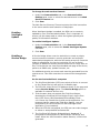
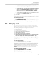
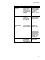
Troubleshooting
DCA
communication
problems
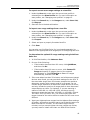
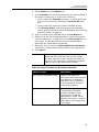
If you are unable to obtain successful communication between the
DCA and the central server after setting the proper communication
method and port (see “Changing and testing the communication
method and port” on page 9) and configuring proxy settings if
necessary (see “Using proxy settings” on page 10), use the
following table to troubleshooting potential communication
problems.
Table 3: Troubleshooting DCA Communication Problems
Check if...
If not...
the selected send method
(HTTP or HTTPS) corresponds
with the port you have chosen
to transmit data through.
change the send method to
correspond with the port
number chosen, or change the
port number to correspond with
the send method chosen.
the port you have selected is
open on the network.
have the network administrator
open the selected port.
your PrintFleet distributor has a
valid SSL security certificate, if
you are attempting to send via
HTTPS.
contact your distributor to
check if they are having
problems with their security
certificate.
12
PrintFleet Optimizer
Using the Printer Data Collector Agent
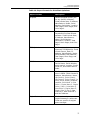
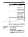
Table 3: Troubleshooting DCA Communication Problems
2.5
Check if...
If not...
the DCA is successfully
collecting data from the
internal network by looking in
the data_queue or
data_archive folder located in
the folder where the DCA was
installed—if there is data in this
folder, the DCA is successfully
collecting data.
the problem is not with the
send method, but with the
collection of data on the
internal network.
the destination URL is correct
by looking in the Summary
area of the Status tab in the
DCA.
obtain a new PIN code and
reactivate the DCA. See
“Installing and activating the
DCA” on page 6.
the network is free of firewalls.
there are not usually problems
with firewalls, but ask the
network administrator if there
is a chance this may be the
problem.
Configuring network scan settings
The DCA network scan settings determine how the DCA collects
information from the internal network, and provides options for
transmitting the information to the central server. Scan profiles can
be used to configure multiple types of network scans that will run
independently, for example, you might want different scan and
transmission settings for networked and local devices.
Network scan settings are independent of communication settings,
which specify how the DCA will communicate with the central
server, and if and how the central server can communicate with the
DCA and/or a specific device on the network (see “Configuring
communication settings” on page 9).
Managing scan
profiles
You can use profiles to configure multiple types of network scans.
For example, you might want to scan networked devices every hour,
and local devices once a day—these would be two different scan
profiles. You might also want a different scan profile for one or two
high priority devices that you want to scan more frequently.
Depending on your environment, you might have multiple uses for
scan profiles, or you might not need more than one. When you first
install the DCA, you will have one scan profile called Default.
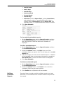
To create a new scan profile:
1. Under the Scan tab, beside Scan Profile, click Add.
13
PrintFleet Optimizer
Using the Printer Data Collector Agent
2. In the New Profile dialog box, enter a name to associate your
new profile with, and click OK.
3. Configure all settings under the General, Advanced, and Local
tabs that apply to the new profile, or copy the settings from
another profile.
4. Click Save.
To edit an existing scan profile:
1. Under the Scan tab, select the profile you want to edit from the
Scan Profile list.
2. Edit settings as applicable under the General, Advanced, and
Local tabs.
3. Click Save.
To delete a scan profile:
1. Under the Scan tab, select the profile you want to delete from
the Scan Profile list.
2. Beside Scan Profile, click Delete.
3. In the Delete Profile? dialog box, click Yes.
Warning
Specifying which
devices to scan
If you delete a scan profile, you will no longer be
collecting information from the devices specified in
the profile, unless they are included in a different
profile.
The DCA only scans the IP addresses and/or hostnames specified in
each scan profile. When the DCA is first installed, it selects a default
set of IP addresses to scan based on either Active Directory or, if
that is not available, the primary network card on the system
installed with the DCA. These IP addresses are automatically added
to the Default scan profile.
If the default set of IP addresses captures all the devices on the
network that you want to scan, and you do not want multiple scan
profiles, you do not have to further specify the devices for the DCA
to scan. If, however, you want to adjust the devices included in the
default scan, or if you have more than one scan profile, you will
need to further configure which IP addresses and/or hostnames to
include.
Single IP addresses, ranges of IP addresses, and hostnames can all
be used to specify devices to include or exclude from a network
scan. There are two general purposes for excluding a device or
range of IP addresses from a network scan: (1) to specifically not
collect information from a device or set of devices; or (2) to remove
IP addresses that you know do not have printing devices on them to
create the most efficient scan range (shorter network scan time).
Important
It is recommended that the network administrator
at the location with DCA installed help set up the
DCA scan range.
14
PrintFleet Optimizer
Using the Printer Data Collector Agent
To add devices to, or exclude devices from, a DCA network
scan range:
1. Under the Scan tab, make sure the correct scan profile is
selected from the Scan Profile list. For more information on
scan profiles, see “Managing scan profiles” on page 13.
2. Under the General tab, in the Ranges area, do one or more of
the following:
•
To automatically obtain an additional default scan range
(from the one specified during DCA installation), click to
select Default Range, and then select either Active
Directory or the applicable network card for the system
installed with the DCA.
•
To specify a range of IP addresses, click to select IP Range,
and enter the IP address of the beginning of the range in the
left box, and the IP address of the end of the range in the
right box.
•
To specify a single IP address, click to select IP Address
and enter the IP address in the box.
•
To specify a hostname, click to select Hostname and enter
the hostname in the box.
3. Click Add or Exclude.
4. Repeat steps 2-3 as necessary.
5. Click Save.
To remove devices, or device exclusions, from a DCA
network scan range:
1. Under the Scan tab, make sure the correct scan profile is
selected from the Scan Profile list. For more information on
scan profiles, see “Managing scan profiles” on page 13.
2. Under the General tab, in the Ranges area, under Scan List,
do one of the following:
•
To remove one or more individual items from the scan range,
click to select the item, and then click Remove.
•
To remove every item from the scan range, click Clear.
3. Click Save.
You can also export and import entire lists of scan ranges. To create
a file with scan range settings, save a text file with each
specification on a separate line. Use parentheses to indicate scan
range exclusions. The following is an example of the contents of a
text file ready for import; the example indicates, from top to
bottom: an IP range to include, a single IP address to include, a
hostname to include, and an IP range to exclude.
10.0.0.1-10.0.0.200
10.0.1.10
examplehostname
(10.0.0.10-10.0.0.50)
15
PrintFleet Optimizer
Using the Printer Data Collector Agent
To export current scan range settings to a text file:
1. Under the Scan tab, make sure the correct scan profile is
selected from the Scan Profile list. For more information on
scan profiles, see “Managing scan profiles” on page 13.
2. Under the General tab, in the Ranges area, under Scan List,
click Export.
3. Save the file to the desired location.
To import scan range settings from a text file:
1. Under the Scan tab, make sure the correct scan profile is
selected from the Scan Profile list. For more information on
scan profiles, see “Managing scan profiles” on page 13.
2. Under the General tab, in the Ranges area, under Scan List,
click Import.
3. Select and open a properly formatted text file.
4. Click Save.
You can also use PrintFleet Suite Pro (purchased separately) to
determine the appropriate scan ranges prior to configuring the DCA.
To determine the optimal IP range settings using PrintFleet
Suite Pro:
1. In PrintFleet Auditor, click Advance Scan.
2. Do one of the following:
•
If the location has less than 100 users, click QuickScan,
and then click Go.
•
If the location has 100 users or more, click Custom IP
Range and specify IP ranges given by the network
administrator or click Fill Ranges to detect IP ranges
automatically, and then click Go.
3. If the scan takes less than 25 minutes, and all document output
devices were found, you can use these settings for the DCA. If
the scan takes longer than 25 minutes, analyze the results to
determine exactly which ranges need to be scanned. Do not
include ranges that have no document output devices on them,
and only include the portions of ranges that do have document
output devices on them. For instance, if you are scanning a
subnet of 192.168.1.1–192.168.1.254, but there are only
document output devices from 192.168.1.1–192.168.1.50 and
192.168.1.200–192.168.1.250, you should input these two
ranges instead of the entire subnet to make the DCA scan more
efficient.
4. Input your tightened scan ranges into the Advance Scan settings
of Auditor, and perform another scan to verify that the scan now
takes less than 25 minutes. If it still takes longer than 25
minutes, and you cannot tighten the scan ranges any further,
you may want to install more than one DCA at the location.
16
PrintFleet Optimizer
Using the Printer Data Collector Agent
Enabling
scanning of
network and/or
local devices
You must enable at least one of network or local device scanning for
the DCA to collect data. For local device scanning to work, you must
also have Local Print Agent installed on computers connected to the
local devices you want to scan. See “Managing local devices with
Local Print Agent” on page 22.
If you have created separate profiles for networked and local
devices, you will enable network device scanning in one, and local
device scanning in the other. For more information on scan profiles,
see “Managing scan profiles” on page 13.
To enable scanning of network and/or local devices:
1. Under the Scan tab, make sure the correct scan profile is
selected from the Scan Profile list. For more information on
scan profiles, see “Managing scan profiles” on page 13.
2. Under the General tab, in the Scanning Options area, do one
or both of the following:
•
Click Network Devices to enable scanning of networked
printing devices.
•
Click Local Devices to enable scanning of locally connected
printing devices.
3. Click Save.
Enabling
broadcast
scanning
Broadcast scanning targets each IP address specified at the same
time, rather than in consecutive order. This makes the DCA network
scan faster. Some networks may not allow this type of scanning for
security purposes. Typically, this is not needed.
To enable broadcast scanning:
1. Under the Scan tab, make sure the correct scan profile is
selected from the Scan Profile list. For more information on
scan profiles, see “Managing scan profiles” on page 13.
2. Under the General tab, in the Scanning Options area, click
Enable Broadcast.
3. Click Save.
Enabling Rapid
Scan
Rapid Scan allows the DCA to use multithreading, which
significantly decreases the time it takes for the DCA to complete a
network scan.
To enable Rapid Scan:
1. Under the Scan tab, make sure the correct scan profile is
selected from the Scan Profile list. For more information on
scan profiles, see “Managing scan profiles” on page 13.
2. Under the General tab, in the Scanning Options area, click
Enable Rapid Scan.
3. Click Save.
The number of threads can be controlled on the Advanced tab. The
setting defaults to a reasonable value for the current system.
17
PrintFleet Optimizer
Using the Printer Data Collector Agent
Setting the scan
and transmission
interval
The scan interval determines how often the DCA will scan the
network and transmit the collected information to your PrintFleet
server. The default scan interval is 30 minutes.
It is generally not useful to set a scan interval for more than every
30 or 60 minutes. For example, new information is posted to
PrintFleet Optimizer every 10 minutes, but new alerts are generated
approximately every 30 minutes.
Note
The scan interval is the time from the end of one
scan to the start of the next scan.
To change the scan interval:
1. Under the Scan tab, make sure the correct scan profile is
selected from the Scan Profile list. For more information on
scan profiles, see “Managing scan profiles” on page 13.
2. Under the General tab, in the Transmission Options area,
type or select the desired scan interval, in minutes, in the Scan
Interval box.
3. Click Save.
Setting the
network timeout
The network timeout is the amount of time that the DCA will wait
for a networked device to respond back with its information. The
default network timeout is 250 milliseconds.
The network timeout only needs to be adjusted if the DCA is not
collecting complete information from networked devices. If, when
you perform a DCA scan, certain data fields which should be
populated are reporting no information, you may need to increase
the network timeout to 500 or 1000 milliseconds. However, the
higher the network timeout is set, the longer the DCA scan will
take. There may be other reasons that the DCA is not collecting
complete information, for example, the device may not store a
specific data field (toner levels, etc.).
To change the network timeout:
1. Under the Scan tab, make sure the correct scan profile is
selected from the Scan Profile list. For more information on
scan profiles, see “Managing scan profiles” on page 13.
2. Under the General tab, in the Transmission Options area,
type or select the desired network timeout, in milliseconds, in
the Network Timeout box.
3. Click Save.
Setting the Local
Print Agent
timeout
The Local Print Agent timeout is the amount of time that the DCA
will wait for the Local Print Agent application to respond back with
information from a locally connected device. The default Local Print
Agent timeout is 10,000 milliseconds per system. Local device
collection takes substantially longer than networked device
collection because of the extra step needed to go through the
connected computer via the Local Print Agent application.
18
PrintFleet Optimizer
Using the Printer Data Collector Agent
The Local Print Agent timeout only needs to be adjusted if the DCA
is not collecting complete information from locally connected
devices. There may be other reasons that the DCA is not collecting
complete information, for example, the device does not store a
specific data field (toner levels, etc.), or a Local Print Agent is not
installed on the computer connected to the local device. See
“Managing local devices with Local Print Agent” on page 22.
To change the Local Print Agent timeout:
1. Under the Scan tab, make sure the correct scan profile is
selected from the Scan Profile list. For more information on
scan profiles, see “Managing scan profiles” on page 13.
2. Under the General tab, in the Transmission Options area,
type or select the desired Local Print Agent timeout, in
milliseconds, in the Local Print Agent Timeout box.
3. Click Save.
Setting the
number of SNMP
retries
The number of SNMP retries entered in the DCA settings is the
number of times the DCA will attempt to get information from a
device that is responding with incomplete or no information.
Increasing the number of SNMP retries may increase the
completeness of a DCA scan, but will also increase the amount of
time it takes to complete a network scan.
To change the number of SNMP retries used:
1. Under the Scan tab, make sure the correct scan profile is
selected from the Scan Profile list. For more information on
scan profiles, see “Managing scan profiles” on page 13.
2. Under the General tab, in the Transmission Options area,
type or select the desired number of SNMP retries in the SNMP
Retries box.
3. Click Save.
Using Focus
Scans
Without using Focus Scan, the DCA will scan each IP address, IP
range, and hostname specified in the scan range settings every
time the DCA performs a full network scan. Using Focus Scan, you
can specify a periodic interval for the DCA to perform a full network
scan, and the scans performed between the intervals will scan only
devices found during the previous full network scan.
Using Focus Scan can decrease the amount of total time and
bandwidth that the DCA occupies, particularly on large networks,
while ensuring that new or relocated document output devices are
discovered on a periodic basis.
To enable Focus Scan:
1. Under the Scan tab, make sure the correct scan profile is
selected from the Scan Profile list. For more information on
scan profiles, see “Managing scan profiles” on page 13.
2. Under the Advanced tab, in the Focus Scan Options area,
click to select the Enable Focus Scan check box.
19
PrintFleet Optimizer
Using the Printer Data Collector Agent
3. Specify how often you want a full network scan to run by
selecting either Days, Hours, or Minutes from the list, and
entering a number for the interval beside Full Discovery
Every. For example, if you enter 5 and select Days, a Focus
Scan will run once every five days.
4. Click Save.
Storing SNMP
community
strings
Community strings act as passwords on networked devices that
limit access via SNMP. Since the DCA uses SNMP to collect data
from devices, any custom community strings on printing devices
put in place by network administrators can be manually entered in
the DCA to allow it SNMP access to the device. Most devices have a
community string of public, and the DCA stores a community
string of public by default.
To store community strings in the DCA:
1. Under the Scan tab, make sure the correct scan profile is
selected from the Scan Profile list. For more information on
scan profiles, see “Managing scan profiles” on page 13.
2. Do one or more of the following under the Advanced tab, in the
SNMP Community Strings area:
•
To add a community string, type an applicable community
string in the text box, and click Add. Repeat as necessary.
•
To remove a community string, click to select a previously
entered community string, and then click Remove.
•
To reorder the list of community strings, click to highlight a
community string, and then click either the Up or Down
button. Repeat as necessary. When the DCA encounters a
device using a community string during the network scan, it
will attempt to use the first community string listed, then the
next, etc., until it is successful or it runs out of community
strings to attempt.
3. Click Save.
Masking private
data
For privacy reasons, the following types of information that the DCA
collects can be masked in the transmission file to the central server:
•
IP addresses of devices included in the network scan
•
Telephone numbers collected from devices (masked by default)
•
DCA host system information (IP address, MAC address, subnet,
etc.)
To mask private information in DCA transmission files:
1. Under the Scan tab, make sure the correct scan profile is
selected from the Scan Profile list. For more information on
scan profiles, see “Managing scan profiles” on page 13.
2. Under the Advanced tab, in the Privacy Options area, do one
or more of the following:
•
Click to select the Enable IP Masking check box to mask
device IP addresses.
20
PrintFleet Optimizer
Using the Printer Data Collector Agent
•
Click to select the Enable Phone-Number Masking check
box to mask telephone numbers collected from devices
(masked by default).
•
Click to select the Enable DCA Host Info Masking check
box to mask DCA host system information.
3. Click Save.
Enabling SNMP
traps
SNMP traps are alerts generated by a device that allow information
to be sent from a device immediately without having to
continuously request information. For example, if a device
experiences an error, by enabling SNMP traps, you can be notified of
the error immediately instead of waiting until your regularly
scheduled DCA scan.
Prior to enabling SNMP traps on the DCA, you need to specify in the
internal configuration for each device that SNMP traps should be
sent to the IP address of the system installed with the DCA. This
only needs to be done for devices that you want to receive SNMP
traps from.
After SNMP traps are enabled on the DCA, each SNMP trap received
will trigger the DCA to perform a regular data scan on only the
device that sent the SNMP trap. The results from this scan will
immediately be sent to the central server.
To enable SNMP traps:
1. Under the Scan tab, make sure the correct scan profile is
selected from the Scan Profile list. For more information on
scan profiles, see “Managing scan profiles” on page 13.
2. Under the Advanced tab, in the Miscellaneous area, click to
select the Enable SNMP Traps check box.
3. Click Save.
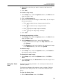
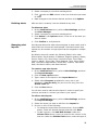
Disabling real
time DCA status
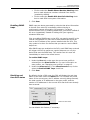
By default, during a DCA scan, the DCA will display the real time
status of the scan under the Status tab. This includes the profile
name of the current scan, the IP address currently being scanned,
the total number of IP addresses in the scan profile, and the
number of IP addresses in the current DCA scan that have already
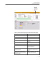
been scanned.
Real time DCA status
You can disable this feature, if necessary.
21
PrintFleet Optimizer
Using the Printer Data Collector Agent
To disable real time DCA status:
1. Under the Advanced tab, in the Miscellaneous area, click to
disable Show Realtime DCA Status.
2. Click Save.
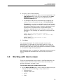
2.6
Managing local devices with Local Print Agent
There are three steps that must be taken to collect local printer
data using the DCA:
1. Add the IP addresses/ranges of computers connected to local
printers to the DCA network scan. See “Specifying which devices
to scan” on page 14.
2. Enable the local device scanning option. See “Enabling scanning
of network and/or local devices” on page 17.
3. Install Local Print Agent on computers connected to local
printers (instructions follow).
Local Print Agent allows the DCA to obtain information directly from
locally connected printing devices. The Local Print Agent application
must be installed on each computer connected to a local printer that
you want to collect information from. Ideally, Local Print Agent will
be installed on all computers at any location where you want to
collect local printer information. This will allow you to collect
information from new local printers as soon as they are connected.
There are three methods to install Local Print Agent:
•
Manual installation from the local printer host computer
•
DCA push tool installation (manual and automated)
•
Third party push tool installation
In environments that do not allow push installation tools, you may
be required to manually install the Local Print Agent application on
each computer connected to a local printer.
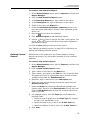
To install Local Print Agent manually from the local printer
host computer:
•
Run the Local Print Agent.msi file on the computer you want
to install Local Print Agent on. The installation file is found by
default in: program files\Printer DCA\Support folder. The
installation file can be copied to a USB drive, CD, etc. for
portability.
The DCA has an embedded push install utility specifically for Local
Print Agent. In addition, you can schedule periodic push installs to
your entire DCA scan range to ensure that Local Print Agent gets
installed to any new computers on the network.
22
PrintFleet Optimizer
Using the Printer Data Collector Agent
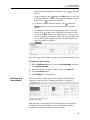
To push install Local Print Agent from the DCA:
1. Under the Scan tab, make sure the correct scan profile is
selected from the Scan Profile list. For more information on
scan profiles, see “Managing scan profiles” on page 13.
2. On the Tools menu, select Local Agent Management.
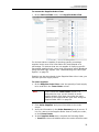
3. Click Scan All. This will scan all IP addresses included in the
selected scan profile.
4. Under the IP Address column, click to select the check boxes
beside each IP address belonging to a computer you want to
install Local Print Agent on. Optionally, click All, None, Not
installed, or Installed to automatically select a set of IPs.
5. If you are not currently logged onto the computer as an
administrator, in the Credentials area, click Change. Enter the
local administrator credentials (for the target OS) in the
Username, Password, and Domain boxes, and then click OK.
6. Click Install.
To schedule regular push installs using the DCA:
1. Under the Scan tab, make sure the correct scan profile is
selected from the Scan Profile list. For more information on
scan profiles, see “Managing scan profiles” on page 13.
2. Under the Local tab, select the Enable Push Install check box.
3. In the Change Push Install Credentials screen, enter the
credentials of the user that belongs to the local administrator
group on the target OS.
Warning
These credentials will be saved in an encrypted
format in the DCA. If you do not want these
credentials saved, do not enable scheduled push
installs.
4. Beside Start, select a start date and time for the automated
push install.
5. Beside Repeat, select the interval you want to perform the push
install at.
6. Click Save.
If the environment already uses a third party push installation tool,
you can use that to push install the Local Print Agent.msi file.
The installation file can be found in the Printer DCA\support folder
on the system installed with the DCA (its default location). Refer to
the user guide for the third party push installation tool for further
instructions.
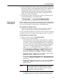
2.7
Viewing queue, archive, and log files
For troubleshooting purposes, you might want to view DCA queue,
archive, or log files.
23
PrintFleet Optimizer
Using the Printer Data Collector Agent
Queue and archive files are copies of DCA scan result files; queue
files have not yet been transmitted to the central server, while
archive files have already been transmitted. The presence of queue
files indicates that the DCA is not successfully transmitting
information to the central server (unless the DCA is in the process
of transmitting the most recent file). Queue and archive files are
encrypted in the proprietary .pfd format and contain the complete
results of a single DCA network scan.
Log files are in .log format and are not encrypted. Log files contain
summary information for all DCA scans that occurred on a specific
date, including scan times, transmission results, DCA application
information, intelligent update actions, and the IP addresses and
vendors of discovered devices. Log files do not include specific
printing device data fields (meters, toner levels, etc.). By default,
log files are not sent to the central server, but this can be enabled.
Queue and archive files can only be viewed using the File Viewer
included in the DCA. Log files can also be viewed using this, but can
also be viewed in any word processing or other application that
supports .log files.
To locate the correct file, queue and archive file names have date
and time stamps as part of the file name, and log files have a date
stamp.
To view queue, archive, or log files in the DCA:
•
Under the File Viewer tab, do one of the following:
•
To open and view a queue file, click the file folder icon (
)
beside Total files in queue, and select and open the
desired file.
•
To open and view an archive file, click the file folder icon
(
) beside Total files in archive, and select and open
the desired file.
•
To open and view a log file, click the file folder icon (
)
beside Open Log file from, and select and open the desired
file, or select a date via the dropdown.
Alternatively, you can drag and drop any of the files into the File
Viewer area.
Deleting old
archive and log
files
By default, the DCA automatically deletes archive and log files after
30 days. If necessary you can adjust the number of days before
these files are deleted, or even stop the DCA from deleting the files
at all.
To change the period after which the DCA automatically
deletes old archive files:
•
Under the File Viewer tab, use the Keep archived files for
combo box to specify the maximum number of days you want to
24
PrintFleet Optimizer
Using the Printer Data Collector Agent
retain archived files. Set the value to 0 if you do not want older
archive files to be automatically deleted.
To change the period after which the DCA automatically
deletes old log files:
•
2.8
Under the File Viewer tab, use the Keep log files for combo
box to specify the maximum number of days you want to retain
log files. Set the value to 0 if you do not want older log files to
be automatically deleted.
Configuring language and read/write settings
The language for the DCA will be automatically selected during
installation, based on the default language selected for your
Windows operating system.
To change the DCA language settings:
•
On the Options menu, point to Language, and then do one of
the following:
•
Click Windows Default to toggle using the default language
for your Windows operating system.
•
Select the appropriate language from the list.
The DCA has full write permissions enabled at installation, but readonly permissions can be set through use of a password. This will
prevent anyone without the password from changing any of the
DCA settings.
To make the DCA read-only:
1. On the Options menu, point to Read-Only Mode, and then
click Read-Only.
2. In the Set Password dialog box, enter the password you want
to use to disable read-only mode, and then click OK.
To disable read-only mode:
1. Click Unlock in the lower right corner of the DCA.
2. In the Enter Password dialog box, enter the password
currently set for read-only mode, and then click OK.
The password for read-only mode can be changed during read-only
mode, provided you have the current password.
To change the read-only mode password:
1. On the Options menu, point to Read-Only Mode, and then
click Change Password.
2. In the Enter Password dialog box, enter the current password
for read-only mode, and then click OK.
3. In the Set Password dialog box, enter the desired new
password for read-only mode, and then click OK.
25
PrintFleet Optimizer
Using the Printer Data Collector Agent
2.9
Updating the DCA software
To take advantage of the latest data collection capabilities, feature
enhancements, and bug fixes, it is important to periodically update
the DCA software.
You can update the DCA manually, or your distributor may update
the DCA software for you if you have Intelligent Update enabled.
See “Enabling Intelligent Update” on page 11.
To update the DCA software manually:
•
On the Help menu, click Check for Updates.
•
The update type allows for installation of Beta and Alpha
releases (if available), or restricts updates to only stable
releases.
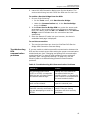
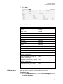
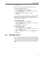
2.10 Understanding the network load associated
with the DCA
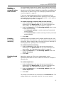
The following table shows approximate network byte load for
various DCA scans, compared to the network load associated with
loading a single standard web page.
Table 4: Network Byte Load Associated with the DCA
Event
Approximate Total Bytes
Loading a single standard web
page
60 KB
DCA scan, blank IP
5.2 KB
DCA scan, 1 printer
7.2 KB
DCA scan, 1 printer, 1 254 local
IP addresses
96 KB
DCA scan, network of 15
printers and 254 local IP
addresses
125 KB
26
PrintFleet Optimizer
Using PrintFleet Optimizer
Chapter 3
Using PrintFleet Optimizer
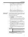
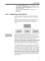
The PrintFleet Optimizer web console is the primary means by which
users view imaging device data, configure reports, and manage the
system.
This chapter discusses all aspects of using the PrintFleet Optimizer
web console.
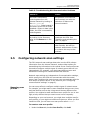
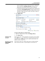
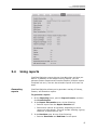
3.1
Working with the interface
The PrintFleet Optimizer web console makes it easy to access the
information you need from anywhere with an Internet connection.
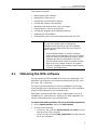
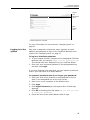
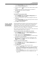
The PrintFleet Optimizer interface has three main components:
•
The header area
•
The navigation area
•
The main display area
The specific items displayed in each area, as well as what is
displayed on the home page, will depend on the specifications of the
user account.
27
PrintFleet Optimizer
Using PrintFleet Optimizer
Header
area
Navigation
menu
Main
display
area
PrintFleet Optimizer Interface
For more information on user accounts, “Managing users” on
page 67.
Logging in to the
system
Each user is assigned a unique user name (typically an email
address) and password to log in to the PrintFleet Optimizer web
console. See “Managing users” on page 67.
To log in to PrintFleet Optimizer:
1. In your browser window, navigate to your designated PrintFleet
Optimizer URL, for example, https://secure.printfleet.com.
This should have been obtained from your PrintFleet dealer.
2. Enter your user name and password in the designated boxes,
and then click Login.
If you have forgotten your password, you can request a password
reset if your user name is an email address.
To request a password reset if you forgot your password:
1. Enter your user name (must be an email address for this to
work) in the designated box on the login screen.
2. Enter one or more characters in the password box.
3. Click Login.
4. Click Forgot Password (this will appear after a failed login
attempt).
5. Click OK in the dialog box that states Are you sure you wish
to reset your password?
6. Check the inbox of the email address used to login.
28
PrintFleet Optimizer
Using PrintFleet Optimizer
Note
While we strive to support all popular browsers, we
recommend that you use the latest version.
If you are using Internet Explorer 6, upgrading to
Internet Explorer 7 or 8, or another browser such
as Firefox or Safari will result in a significantly
improved user experience, due to improved speed
and standards compliance.
The first time you log in to PrintFleet Optimizer, you
will see the End User License Agreement. After this
is accepted once, it will not be shown again.
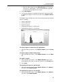
Using the search
function
The search function in Optimizer allows you to quickly find specific
items in the system.
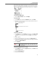
To search for a specific item in PrintFleet Optimizer:
1. Type your search string in the text box on the right side of the
header area of the Optimizer interface.
2. Press Enter, or click
.
Results are displayed and separated into users, devices, and
groups.
User results display the login name, first name, last name, last login
date and time, the groups and roles assigned to the user, and links
to edit, copy, or delete the user from the user edit screen (if
applicable to the current user). See “Managing users” on page 67.
Device results display the device name, management status, group,
serial number, IP address, MAC address, asset number, location,
last active date and time, and a link to edit the device (if applicable
to the current user). See “Managing devices” on page 69.
Group results display the group name, parent groups, and a link to
the group edit screen (if applicable to the current user). See
“Managing groups” on page 62.
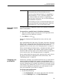
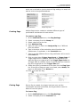
Changing your
preferences
Preferences, including your password and the way you want device
names to display throughout the system, can be changed. It is
recommended you change your password periodically for additional
security. Passwords are encrypted, and cannot be recovered, so you
must change your password if you lose it. If you do not have access
to the area to change your password, you must request a reset
from your distributor if you want to change it.
To change your preferences:
1. Do one of the following:
•
Click Preferences on the upper right side of the interface.
•
On the Settings menu, click My Preferences.
29
PrintFleet Optimizer
Using PrintFleet Optimizer
2. Do one or more of the following:
•
To change your password, type your current password in the
Old Password box, type your new password in the New
Password box, and retype your new password in the
Confirm Password box.
•
To change the way device names display throughout the
system, enter an acceptable string in the Device Name
Template box, or select a method from the list underneath.
The following properties are accepted: $description, $name,
$id, $serial, $asset, $ip, $mac, $location, $hostname, $lcd,
$systemname, $systemlocation, $systemdescription,
$grouping, $groupbreadcrumb, $userlogin, $userid, and
$username. The following are examples of strings that can
be used:
$name (Serial: $serial, Asset: $asset)
sample output: HP 1000 (Serial: 1234, Asset: ABC)
$name-$ip-$mac
sample output: HP 1000-192.168.1.110400:01:02:aa:bb:cc
3. Click Save.
Your password must be of a certain strength, as set by the
administrator. The Strength bar must turn green for it to be an
acceptable password. To increase the strength of your password,
use both upper and lower case, both letters and numbers, symbols,
or increase the length of the password.
See “Managing users” on page 67 for instructions on how to force a
user to change their password the next time they log into the
system.
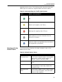
3.2
Working with device views
There are several default device views in PrintFleet Optimizer. You
can also create unlimited custom device views that contain the
precise information you want to see.
To view data using an available device view:
1. On the Device Views menu, click to select the device view you
want to use from the following, or any custom view:
•
Technical View
•
Supplies Order View
•
Alerts
•
Maps
30
PrintFleet Optimizer
Using PrintFleet Optimizer
2. On the left side of the screen, select the group that contains the
devices you want to view. Beside each group, it will indicate how
many devices reside in that group; for example, (5 of 15)
indicates that 5 devices are in the top level of that particular
group, and 10 additional devices reside in subgroups of that
group, for a total of 15 devices.
3. Use the lower toolbar to change the number of devices shown,
scroll through pages, or refresh the data.
Filtering and
sorting data
Data in a device view can be filtered and sorted. Filtering allows you
to view a subset of the devices in the selected group. Sorting allows
you to view information in ascending or descending order.
To sort data in a device view:
•
Click the column title you want to sort the data by, and click
again to toggle between ascending and descending order.
You can customize a default sort order for each view when creating
or editing a view. See “Creating custom device views” on page 40.
To filter data in a device view:
1. While on a device view, click Change Filters.
2. Do one or more of the following:
•
To filter devices by text string(s) that match all or a portion
of a device name, serial number, asset number, IP address,
or location, click to select the Text check box, and type the
string in the text box. Multiple search strings are separated
by a space, and each string will be searched individually
(e.g. 10.0.0 HP would search both 10.0.0 and HP).
•
To filter devices by managed or unmanaged status, click to
select Managed, Unmanaged, or Both (default is Both).
For more information on managed status, see “Marking
devices as managed, unmanaged, or hidden” on page 74.
•
To filter devices by networked or local status, click to select
Network, Local, or Both (default is Both).
•
To filter devices by managed supplies or service status, click
to select the Managed Supplies and/or Managed Service
check box.
•
To filter devices by last active date, click to select the Active
within last _ days check box, and enter the number of
days in the box.
Note
•
Device views are set to automatically filter based
on last active date for a default number of days.
The default number is 6 days, but this is can be
configured by the administrator.
To filter devices by percent toner remaining, click to select
the Toner check box, and then select the highest percent
31
PrintFleet Optimizer
Using PrintFleet Optimizer
toner remaining you want to view from the list. Optionally,
click to select the Include unknown check box to list
devices with an unknown amount of toner remaining.
•
To filter devices by the last time supplies were ordered, click
to select the Last Supplies Order, and then select the time
interval for last supplies orders that you want to view: never,
less than 1 week, less than 2 weeks, less than 3 weeks, or
less than 30 days ago.
3. Click Apply Filter.
To clear a data filter in a device view:
1. While on a filtered device view, click Change Filters.
2. Click Reset Filter.
Viewing new
devices
Devices that have recently appeared in the system will be marked
). The number of days that a device will be
with a New icon (
marked as new is configured by your system administrator. The
default number of days is 30.
Working with the
traffic light
system
Some device views use a traffic light system to display supplies
status and device status. A legend appears at the bottom of
32
PrintFleet Optimizer
Using PrintFleet Optimizer
applicable device views. The following table describes what each
traffic light icon means for supplies status and device status.
Table 5: Understanding the Traffic Light System
Icon
Status Interpretation
OK
Caution (for supplies, Low Toner)
Warning (for supplies, Out of Toner)
Stale (data has not been collected from the
device for 24 hours)
Unknown (data is not available from the device or
not supported by PrintFleet)
Working with the
default views
The following table describes the data included in each of the
default device views.
Table 6: Default Device Views
Device View
Data Included
Technical View
device name, supplies status, overall status,
page count - month, serial number, IP
address, location, last active date
Alerts
customer, devices, options for managing
alerts
Maps
list of maps, links to each map, number of
devices placed on each map, options for
managing maps
Supplies Order
View
device name, pages in last 30 days, supply
type, current level/status, last order date,
option to order supplies
33
PrintFleet Optimizer
Using PrintFleet Optimizer
Using the
Technical View
The Technical View provides basic information about devices,
including the name, supplies status, device status, yesterday meter
count, serial number, IP address, location, and last active date. You
can Edit and Override this information via Options in the Device
View Manager.
To access the Technical View:
•
On the Device Views menu, click Technical View.
The Technical View will display the traffic light icon for supplies
status and overall status that corresponds to the most significant
status. For example, if a device is out of black toner and low on
yellow toner, the Technical View will display a warning icon under
the Supplies column for the black toner, rather than a caution icon
for the yellow toner.
If you want more information about the status of a device, click on
the device name link and you will be taken to the Device Detail View
for that device. See “Working with the Device Detail view” on
page 41.
Using the
Supplies Order
View
The Supplies Order View displays supplies related information about
devices, including black toner level or status, cyan toner level or
status, magenta toner level or status, yellow toner level or status,
device name, and a link to the report on pages for the last 30 days.
Supplies can also be ordered from the Supplies Order View. You can
Edit, Override, or delete this information via Options in the Device
View Manager.
The email address where supplies orders are sent is set at the group
level for dealer and customer groups. See “Creating, editing, and
deleting groups” on page 62. Multiple, separate orders will be
generated and sent if an order is placed for multiple devices
belonging to different groups with different supplies ordering email
addresses.
Supplies orders are automatically added to the service history of
each applicable device.
34
PrintFleet Optimizer
Using PrintFleet Optimizer
To access the Supplies Order View:
•
On the Device Views menu, click Supplies Order View.
For devices that are capable of reporting specific percentage
supplies levels, toner level information will be displayed as a
percentage. For devices that are not capable of reporting specific
percentage supplies levels, toner level information will be displayed
using the traffic light system. See “Understanding the Traffic Light
System” on page 33.
Supplies can also be ordered via the Supplies Order View. Later, you
can view previous supply orders.
To order supplies:
1. On the Supplies Order View, enter the quantity of each supply
to be ordered in the Toner Order column.
Note
If you include the Toner Order column in a
custom device view, you will be able to order
supplies directly from that view using the same
method as the Supplies Order View. See “Using the
Supplies Order View” on page 34.
2. Click Order Supplies, and you will be taken to the order
screen.
3. Verify the information in the Order Summary area is correct. If
it is not, return to the Supplies Order View to modify the order,
or click Cancel Order.
4. In the Complete Order area, complete the following fields:
•
Email To: the email address where the order should be sent
35
PrintFleet Optimizer
Using PrintFleet Optimizer
5.
•
Email CC: the email address to be copied on the order, by
default, the email associated with your user account
•
Subject: the subject line of the email
•
Note (optional): note to include in the body of the email
Click Send Order.
To view previous supply orders:
1. On the Reporting menu, click Previous Supply Orders. Date,
ordered by, and order information are displayed.
2. Under the Options column, click View Order to see exactly
which devices and supplies were included in a specific order.
The Supplies Order View provides direct access to a page count
report, that displays pages printed over the past 30 days.
To view the Page Counts report for a device:
•
Click the
icon under the Pages (last 30 days)
column, in the row of the device you want to run the report for.
The icon will be a smaller version of the actual report, and can
be used as a quick reference.
For more information about reports, see “Using reports” on
page 47.
If you want more information about the status of a device, click on
the device name link and you will be taken to the Device Detail View
for that device. See “Working with the Device Detail view” on
page 41.
Using the Maps
View
The Maps View allows you to view, upload, and place images of
images of document output devices, computing devices, people,
and other miscellaneous items on one or more maps for each
customer. Document output devices will display their status using
the traffic light system. See “Understanding the Traffic Light
System” on page 33.
36
PrintFleet Optimizer
Using PrintFleet Optimizer
Most browsers also support hovering your mouse pointer over the
device to view basic device information, with a link to the device’s
detail view. See “Working with the Device Detail view” on page 41.
To access the Maps view:
•
On the Device Views menu, click Maps.
To view a map:
1. In the Maps view, under the Options column, click View.
2. Optionally, use the zoom bar or your mouse scroller to zoom in
and out on the map image.
Click to zoom in
Click and drag to zoom in and out
Click to zoom out
To upload a new map:
1. In the Maps view, click Add Map. Alternately, click Option Edit
or View on the existing map and select New in the Settings
tab.
2. Select a group.
3. Enter a recognizable title for the map in the Map name box.
4. Click Browse or type the location of the map image you want to
upload in the Map image box.
5. Click Add Map.
Note
Map images must be in .jpg, .gif, .png, .bmp, .tiff,
or .wmf format.
To place imaging devices on a map:
1. In the Maps view, under the Options column, click Edit for the
map you want to edit.
2. Click the Edit Layout tab.
3. Do one of the following:
37
PrintFleet Optimizer
Using PrintFleet Optimizer
•
Click Add Printer, click to select the device you want to add
from the list, and then click the location on the map that you
want to place the device.
•
Right-click the place on the map image where you want to
place a device, point to Add new printer, and then click to
select a device from the list.
4. Drag the device until it is in the precise location you want it.
5. Click Save.
To place computing devices, people, or other miscellaneous
icons on a map:
1. In the Map view, under the Options column, click Edit for the
map you want to edit.
2. Click the Edit Layout tab.
3. Right-click the place on the map image where you want to place
a computer, building, or person, and do one of the following:
•
To add a computer, point to Add Devices, and click to select
the icon you want to add from the list.
•
To add a person or group of people, point to Add People,
and click to select the icon you want to add from the list.
•
To add other miscellaneous icons, point to Add Misc, and
click to select the icon you want to add from the list.
4. Drag the object until it is in the precise location you want it.
5. Click Save.
To move an imaging device image or other icon:
1. In the Maps view, under the Options column, click Edit for the
map you want to edit.
2. Click the Edit Layout tab.
3. Click and drag the icon you want to move to the new location.
4. Click Save.
To remove an imaging device image or other icon:
1. In the Maps view, under the Options column, click Edit for the
map you want to edit.
2. Click the Edit Layout tab.
38
PrintFleet Optimizer
Using PrintFleet Optimizer
3. Right-click on the icon you want to remove, and then click
Remove.
4. Click Save.
To rotate or flip a map:
1. In the Maps view, under the Options column, click Edit for the
map you want to edit.
2. Click the Edit Layout tab.
3. Do one or more of the following to rotate and/or flip the map to
the correct position:
•
Click
to rotate the map image counterclockwise.
•
Click
to rotate the map image clockwise.
•
Click
to flip the map image horizontally.
•
Click
to flip the map image vertically.
4. Click Save.
To change a map image or title:
1. In the Maps view, under the Options column, click Edit for the
map you want to edit.
2. In the Settings tab, do one or more of the following:
•
Enter a new title for the map in the Map name box, and
click Change.
•
Click Browse or type in the location of a replacement image
in the Select file box, and then click Upload.
To delete a map:
1. In the Maps view, under the Options column, click Delete for
the map you want to delete.
To download a map image:
1. In the Maps view, under the Options column, click Edit or
View.
2. In the Settings tab, click Download and save the image file to
your computer.
Using the Alerts
View
The Alerts view displays details on the recently sent alerts for all
customer groups.
The Alerts view displays the customer name, number of devices
that have recent alerts, and a link to view alert details for each
device.
To view the Alerts view:
1. On the Device Views menu, click Alerts.
39
PrintFleet Optimizer
Using PrintFleet Optimizer
2. Under the Options column, click Details to view the device
name, serial number, LCD, and service code status for each
device with a recent alert for a particular customer.
3. Optionally, to view additional information about a specific
device, click the device name to go to the Device Detail view.
See “Working with the Device Detail view” on page 41.
Creating custom
device views
An unlimited amount of custom device views can be created, so that
you can view the exact information you want, in the way you want
to view it. Custom device views will be added to the Device Views
menu for groups selected to have access.
To create a custom device view:
1. On the Settings menu, click Device View Manager.
2. Click New View.
3. In the Columns area, click to select the data items you want
included in the view. In general, you will want to include at least
one data item that identifies a device, for example, device name
or serial number. Custom Device Fields are denoted by yellow
fill.
4. Enter a title for the custom device view in the Name box.
5. From the Default Sorting lists, choose a default column you
want the data to be sorted by initially, and whether you want the
sorting to be ascending or descending.
6. From the Apply To list, select whether you want the device view
to be available to only yourself (Me) or to specific Groups. If
you select Groups, you must select one or more groups that the
view will be available to.
7. Click and drag the selected data items into the order you want
them to appear on the view. The item at the top of the list will
be displayed as the first item on the left side of the view.
8. Click Save.
Note
If you include the Toner Order column in a
custom device view, you will be able to order
supplies directly from that view using the same
method as the Supplies Order View. See “Using the
Supplies Order View” on page 34.
To edit a custom device view:
1. On the Settings menu, click Device View Manager.
40
PrintFleet Optimizer
Using PrintFleet Optimizer
2. In the row of the device view you want to change, click Edit.
3. Change any properties of the view, including name, default
sorting, apply to properties (including which specific groups can
access the view), and columns (data items).
4. Click Save.
To delete a custom device view:
1. On the Settings menu, click Device View Manager.
2. In the row of the device view you want to remove, click Delete.
3. When prompted, click Confirm.
You can use the override function to allow yourself or specified
groups to see one view instead of another. This view could be a
slight variation of the original view, or it could be something entirely
different. When you delete an override, the properties of the
original device view will be reinstated.
To create a device view override:
1. On the Settings menu, click Device View Manager.
2. In the row of the device view you want to create an override for,
click Override.
3. Create your override view by entering a Name, choosing
Default Sorting and Apply To properties, and selecting data
items in the Columns area.
4. Click Save.
3.3
Working with the Device Detail view
The Device Detail view displays all information, and links to other
areas in the system, relevant to a specific device. An image of the
device model is also included if available.
The lower area of the Device Detail view has tabs for accessing
complete meter breakdowns, supply levels, service information,
miscellaneous device-specific information, and model information.
To access the Device Detail view:
•
Click on a device name link anywhere in the system. Usually this
is while using one of the device views. See “Working with device
views” on page 30.
41
PrintFleet Optimizer
Using PrintFleet Optimizer
Navigate
between
devices in
the same
group
Table 7: Information Displayed in the Device Detail View
Group
Name
IP address
Status
Location
Utilization
Serial number
Asset number
Total coverage (and source)
Individual color coverages (and
source)
Last active (date/time)
MAC address
Firmware
First seen (date)
Install date
Display (with More link to view
previous displays)
Errors (with More link to view
previous errors)
Links to external web sites if
configured for the device’s
group
Supply levels (with ability to
add and remove items from a
supplies order)
Meter breakdowns (with links
to page count reports)
42
PrintFleet Optimizer
Using PrintFleet Optimizer
Table 7: Information Displayed in the Device Detail View
Service information (including
past 100 alerts and flags, and
recent service history)
Miscellaneous device-specific
information
Model information (from the
model database)
Device Type
Page coverages are displayed for each application color, as well as
total. Coverage values can come from a variety of sources—the
source being used will be indicated in brackets beside the
percentage value. The following table describes the various sources.
Table 8: Page Coverage Data Sources
Coverage Data Source
Description
Device Total
A value obtained directly from
the device for the lifetime
average page coverage of the
device.
Device Cartridge
A value obtained directly from
the device for the average page
coverage over the life of the
current cartridge.
Device Total / Device Cartridge
Both Device Total and Device
Cartridge values may display if
both are available.
Estimated1
If there is enough information
to calculate page coverage, but
no page coverage given directly
from the device, a calculated
estimate of page coverage will
be displayed.
Default1
If no page coverage
information is available, a
default percentage of 5% will
be displayed.
1. This value can be set in the Configuration page.
The ERP icon (
) will appear beside the serial number of the
device on the Device Detail view if the device is currently configured
for meter exports. See “Configuring meter exports” on page 79.
Note
You can find additional information, including the
version of the DCA being used, by hovering your
mouse over the device image.
43
PrintFleet Optimizer
Using PrintFleet Optimizer
Clicking on the edit icon ( ) that appears beside the device name
will take you to the Device Information screen, which allows you
to add and edit information to the device record. For more
information, see “Editing device information” on page 70.
Viewing
embedded web
pages
From the Device Detail view, you can view the embedded web page
of the device, provided you are within the internal network that the
device resides.
To view the embedded web page:
•
Viewing
historical LCD
and error
information
Click the IP address of the device. Two options appear:
Internal Webpage and Service Bridge. To access the Service
Bridge for network devices, see “Enabling a Service Bridge” on
page 11.
From the Device Detail view, you can view historical LCD and error
data, useful for determining whether or not there are recurring or
serious problems with a device.
To view historical LCD data:
•
Click More to the right of the Display area.
To view historical error data:
•
Working with the
Supplies tab
Click More to the right of the Errors area.
The Supplies area on the Device Detail view displays toner and nontoner supply levels, supply SKUs, and provides the ability to add
items to a supplies order (if this feature is enabled).
To access supplies information:
•
On the Device Detail view, click the Supplies tab.
To add items to a supplies order:
1. Under the Order column, click the + icon in the row of the
supply you want to order. Click additional times to increase the
order quantity.
2. If you are finished adding items to your order, click Place Order
to proceed to the order screen. See “Using the Supplies Order
View” on page 34.
Working with the
Meters tab
The meters area displays complete meters information, including
standard, virtual, and device-specific meters, for several different
44
PrintFleet Optimizer
Using PrintFleet Optimizer
time periods: today, yesterday, past 7 days, past 31 days, current
month, year, and life of the device. You can also access trend
reports for each of these time periods.
To access meters information:
•
On the Device Detail view, click the Meters tab.
To access a meter trend report:
•
Working with the
Service tab
On the Meters tab, click one of the following column titles for
the time period you want to run the report for:
•
Today. Displays a report showing pages printed since
12:00am on the current day.
•
Yesterday. Displays a report showing pages printed on the
previous day.
•
Past 7 Days. Displays a report showing pages printed
during the previous seven days.
•
Past 31 Days. Displays a report showing pages printed
during the previous 31 days.
•
Current Month. Displays a report showing pages printed
from the start of the current month until the current day.
•
Year. Displays a report showing pages printed from the start
of the current year until the current day.
•
Life. Displays a report showing pages printed from the start
of when the DCA began collecting information from the
device until the current day.
The service area provides quick access to information about the
past 100 alerts, past 100 flags, and service history for the device.
To access service information:
1. On the Device Detail view, click the Service tab.
2. Do one or more of the following:
•
To view past alerts, click the
icon beside Alerts and view
the Send Date, To, From, and Subject for the past 100 alert
to go
emails directly in the Service tab, or click Alerts or
to the Alert Settings screen. See “Using alerts” on page 56.
•
To view past flags, click the
icon beside Flags to view the
Send Date, To, From, and Subject for the past 100 flag
emails directly in the Service tab, or click Flags or
to go
to the Flag Settings screen. See “Using flags” on page 60.
•
To view the service history for the device, click the
icon
beside Service History to view the Date/Time, Severity,
45
PrintFleet Optimizer
Using PrintFleet Optimizer
Updated By, Maintenance, and Notes for each service history
item directly in the Service tab, or click Service History or
to go to the Service History screen. See “Viewing,
editing, and exporting service history” on page 73.
Working with the
Miscellaneous
tab
The miscellaneous area provides additional device information that
does not fit into any particular category. This information will vary
by device, but may include such things as paper levels, amount of
memory, duplex capability, etc.
To access miscellaneous device information:
•
Working with the
Model tab
On the Device Detail view, click the Miscellaneous tab. This
will display the Label, Value, and Date the information was
obtained for each miscellaneous data item.
The model area provides information about the device model, rather
than the specific device. This information is stored in the model
database, and is not collected by the DCA (although some of the
information may also be available through the DCA).
You can edit the model that a device is associated with. See “Editing
device information” on page 70.
To access model information:
•
On the Device Detail view, click the Model tab. The
information contained here is displayed below.
46
PrintFleet Optimizer
Using PrintFleet Optimizer
3.4
Using reports
PrintFleet Optimizer reports let you view data when and how you
want it. In addition to the default Primary Reports, you can
generate Custom Reports and Executive Reports (multiple reports
combined into one). You can also schedule reports to be sent via
email.
Generating
reports
PrintFleet Optimizer allows you to generate a variety of Primary,
Custom, and Executive reports.
To generate a report:
1. On the Reporting menu, point to Report Console, and then
click Create Report.
2. In the Report Information area, do the following:
•
Select a report from the Report Selection list.
•
Select other options as necessary, depending on which
report you have chosen. This may include selecting a group,
customer, a specific device, etc.
3. In the Run Now area, do one of the following:
•
Select a Start Date and End Date for the report.
47
PrintFleet Optimizer
Using PrintFleet Optimizer
•
Select a date range from the Data Range list (This Month,
This Year, or Last Month). This will automatically populate
the start and end dates for the report.
4. Click View Report.
5. For Executive Reports, navigate through each individual report
by selecting a page to view from the list in the Report Viewer
header.
The Report Viewer allows you to do various things with a generated
report, including:
•
View in chart form.
•
View in data form.
•
Email the report.
•
Download the report in .pdf format.
•
Download the report in .csv format.
To view a report in chart form (if applicable):
•
After generating a report, in the Report Viewer, click the Chart
tab.
To view a report in data (text) form:
•
After generating a report, in the Report Viewer, click the Data
tab.
To email a report:
1. After generating a report, in the Report Viewer, type in the
email address you want to send the report to in the E-mail box.
2. Click Send.
To download a report in .pdf format:
•
After generating a report, in the Report Viewer, click Options,
and then click Download PDF.
To download a report in .csv format:
•
After generating a report, in the Report Viewer, click Options,
and then click Download CSV.
48
PrintFleet Optimizer
Using PrintFleet Optimizer
Primary reports are default reports you can generate to view
information about document output devices.
Table 9: Description of Primary Reports
Report
Description
Advanced Volume Report
A text report that displays
device name, serial number,
start page count, end page
count, page total, mono total,
color total, copier mono, copier
color, print mono, print color,
fax count, IP address, asset
number, and last active date.
Additional machine-specific
meters can be shown if
selected. You can choose to run
the report for either managed
or unmanaged devices.
CPC Report
A text report that displays the
device name, serial number,
asset number, location, count
mono, count color, CPC mono,
CPC color, CPC total mono, CPC
total color, and CPC total based
on a specified date range.
Individual CPC charges are
based on inputs from the CPC
Assignment screen. See
“Assigning CPC charges” on
page 78.
Current Meters
A text report that displays the
device name, serial number, IP
address, asset number, all
available meters (standard and
custom) based on a specified
end date, and the last active
date, for either managed or
unmanaged devices for the
selected group.
Individual Page Count Report
A graphical report that displays
total page count, total
monochrome count, and total
color count for a single device
over a specified time period.
49
PrintFleet Optimizer
Using PrintFleet Optimizer
Table 9: Description of Primary Reports
Report
Description
Individual Toner Level Report
A graphical report that displays
black, cyan, magenta, and
yellow toner levels (where
applicable) for a single device
over a specified time period.
Individual Page & Toner Report
A graphical report that displays
black pages, color pages, and
black, cyan, magenta, and
yellow toner levels for a single
device over a specified time
period.
Individual Misc. Supplies Report
A graphical report that displays
the level of a specified supply
item (i.e. imaging drum), for a
single device over a specified
time period.
Power Usage Report
A text report that displays the
device name, serial number,
operating watts, idle watts,
total pages (in the selected
time period), estimated kWh
usage, estimated cost (at
selected kWh price), power
cost per page, and total power
cost of the selected group over
the specified time period.
Toner Reorder Report
A text report that displays the
device name, asset number,
mono and color pages based on
a specified start date, supply
(toner) types, and current
supply levels for the selected
group.
Custom reports are created by your PrintFleet administrator and are
accessed through the PrintFleet Optimizer console. Some custom
reports are included in the system.
Editing and
deleting reports
Report properties, including name/title, description, role
permissions, code base, chart type, or individual reports for
Executive reports can be changed at any time, with the exception of
the code base and chart type for Primary reports, which cannot be
changed.
To edit a report:
1. On the Administration menu, point to Reports, and then click
Report Manager.
50
PrintFleet Optimizer
Using PrintFleet Optimizer
2. Click Edit in the row of the report you want to change.
3. Make desired changes to the report.
4. Click Save.
All reports can be deleted at any time.
To delete a report:
1. On the Administration menu, point to Reports, and then click
Report Manager.
2. Click Delete in the row of the report you want to delete.
3. Click Confirm to verify that you want to delete the report.
Scheduling
reports
Scheduled reports are configured to email to a specified recipient at
predetermined intervals.
A scheduled report email contains the data and chart (if applicable)
embedded in the body of the email, as well as the report in a .csv
format attachment.
To create a scheduled report:
1. On the Reporting menu, point to Report Console, and then
click Create Report.
2. In the Report Information area, do the following:
•
Select a report from the Report Selection list.
•
Select other options as necessary, depending on which
report you have chosen. This may include selecting a group,
customer, a specific device, date range, etc.
3. Click to select Set Up Schedule.
4. Type an email subject line for the report in the Schedule Name
box.
5. Type in one or more email addresses for the report to be sent to
in the Email address(es) box. Multiple email addresses can be
separated by commas, semicolons, or spaces.
6. In the Start Date area, type or select a start date and time for
the report to begin sending.
7. In the Repeat area, select one of the following intervals for the
report to send:
•
Daily. Type in the interval, in days, that you want the report
to run.
•
Weekly. Type in the interval, in weeks, that you want the
report to run, and select the day of the week that you want
the report to run.
•
Monthly. Type in which day of the month and interval in
months that you want the report to run.
•
Advanced. Select which occurrence of which day of the
week in a month, and interval in months that you want the
report to run.
8. In the Date Range area, select one of the following intervals for
each report to analyze:
51
PrintFleet Optimizer
Using PrintFleet Optimizer
•
Last 24 hours
•
Last 7 days
•
Last 30 days
•
Previous Month
•
Current Month
•
Last 90 days
•
Advanced. Select a Report Start, typically Month Start,
and optionally select +/- a specified amount of days or
months. Select a Report End, typically Month End, and
optionally select +/- a specified amount of days or months.
9. Click Save Schedule.
To view existing scheduled reports:
•
On the Reporting menu, point to Report Console, and then
click Scheduled Reports. The email address, title, last sent
date, and options to edit and delete each schedule are
displayed.
To edit a scheduled report:
1. On the Reporting menu, point to Report Console, and then
click Scheduled Reports.
2. Under the Options column, click Edit in the row of the
scheduled report you want to edit. This will take you to the Edit
Report tab.
3. Make the changes you want to the scheduled report. In addition
to the standard items, you also have the option to change the
Next Send Date. The last sent date will also be displayed.
4. Click Save Schedule.
To delete a scheduled report:
1. On the Reporting menu, point to Report Console, and then
click Scheduled Reports.
2. Under the Options column, click Delete in the row of the
scheduled report that you want to delete.
3. Click Confirm to verify deletion of the schedule.
Building
Executive
Reports
Executive Reports contain multiple individual reports in a single
document. An unlimited amount of custom Executive Reports can
be created.
52
PrintFleet Optimizer
Using PrintFleet Optimizer
To create a new Executive Report:
1. On the Administration menu, point to Reports, and then click
Report Manager.
2. Click the New Executive Report button.
3. In the Executive Report box, type a title for the report.
4. In the Description box, type a description of the report.
5. Select a report from the Report list.
6. Under the Hardcoded Parameters (Optional) column, set
any fixed report parameters, such as a title, applicable group,
device, etc.
7. Click the
icon to save your changes.
8. Click Add New Report to add additional reports.
9. Use the
and
icons to arrange the order of the reports. The
report at the top of the list will be the first report displayed in
the executive report.
10. Click the Save button to save the entire report.
See “Editing and deleting reports” on page 50 for information on
editing and deleting executive reports.
Building Custom
Reports
Administrators can create their own Custom Reports. Custom
Reports can draw on any information available in your PrintFleet
database.
To create a new Custom Report:
1. On the Administration menu, point to Reports, and then click
Report Manager.
2. Click the New Custom Report button.
3. Type a name for the report in the Name box.
4. Type a title for the report in the Title box. This is the title that
will appear at the top of a generated report, and can include
variables listed under the Substitutions tab.
5. Optionally, enter a description in the Description box.
6. Select the roles that will be able to view the report from the
Restrict Access area.
7. Under the PFSQL tab, type the code that will generate your
custom report, and then click Check Syntax to verify the code.
Click the Substitutions tab to view the variables that can be
used in the code.
8. For graphical reports, click the Chart tab and complete the
following fields:
•
Select the type of graph from the Chart Type list. Options
are Bar, Line, Stacked Bar, or Pie.
•
Specify the field for the x-axis in the X-Axis Field box.
•
Specify the field(s) for the y-axis in the Y-Axis Field box.
9. Click Save.
53
PrintFleet Optimizer
Using PrintFleet Optimizer
See “Editing and deleting reports” on page 50 for information on
editing and deleting custom reports.
Using the Cost
per Image (CPI)
Calculator
The CPI Calculator is designed to help you calculate what you
should be charging your clients on a per page basis. Using the page
counts collected and stored in the PrintFleet database, you can
combine every component in the cost of printing into a per page
charge, including toner, parts, labor, and margin. If one or more
components are not applicable to your program, you simply leave
them out of the calculation.
Note
The CPI calculator uses the page counts from the
previous month to calculate suggested charges.
To calculate per page charges using the CPI Calculator:
1. On the Reporting menu, click CPI Calculator.
2. Select a company from the Customer list.
3. Click to select the check box for each component you want
included in your CPI calculation, and configure default settings
for the components as necessary:
•
Note
Supplies. Costs for this component are drawn from the
default model records for each device, and can be adjusted
after cost components are selected, or can be uploaded into
the system using the import/export function. See “Exporting
and importing device information” on page 75.
Default toner prices and yields are drawn from the
PrintFleet Model Database. Toner prices stored in
this database are observed from major retail
chains at the time the model was added to the
database, or from periodic updates thereafter.
Toner yields stored in the database are in most
cases the stated OEM yields unless those were
unavailable.
•
Labor. Enter a per page cost in one or both of the Copier
and Laser rows. The text boxes will hold up to four decimal
places. Do not type $ in front of your per page costs.
•
Parts. Enter a per page cost in one or both of the Copier and
Laser rows. The text boxes will hold up to four decimal
places. Do not type $ in front of your per page costs.
•
Equipment. Costs for this component are drawn from the
default model records for each device, and can be adjusted
after cost components are selected.
•
Margin. This component does not need to be selected, and
is based entirely on the percentage entered in. Enter a
margin percentage in one or both of the Copier and Laser
54
PrintFleet Optimizer
Using PrintFleet Optimizer
rows. If you want a forty percent margin, you should type in
40% (not a decimal number).
4. Click Assign Values.
5. Click to select the check box to the left of each device name that
you want to include in the CPI calculation. Optionally, you can
select the Check / Uncheck all Copiers check box, and the
Check / Uncheck all Lasers check box to select all devices.
6. Edit any numbers in the Copier Devices and Laser Devices
areas as desired.
7. Read and click to accept the Terms and Conditions of using the
CPI Calculator.
8. Click Generate Report.
The CPI report generated includes the following:
•
Per page charge breakdowns for each component of the cost
(supplies, parts, labor, equipment, margin).
•
Suggested charge for monochrome pages printed for each
device.
•
Suggested charge for color pages printed for each device.
•
Weighted average monochrome print charge for the fleet.
•
Weighted average color print charge for the fleet.
•
Options to email or download the report.
To email a CPI report:
1. Generate a CPI report as described in “To calculate per page
charges using the CPI Calculator:” on page 54.
55
PrintFleet Optimizer
Using PrintFleet Optimizer
2. On the report screen, in the Send Via E-mail box, type in the
email address you want the report to be sent to.
3. Click Send.
To download a CPI report:
1. Generate a CPI report as described in “To calculate per page
charges using the CPI Calculator:” on page 54.
2. On the report screen, click Download, and save the report to
the desired location.
3.5
Using alerts
Alerts are configured to notify you via email when a document
output device has a status that you have indicated you want to be
notified of. This gives you the ability to respond to service issues
quickly. Recently sent alerts are also summarized on the Alerts
view; for more information, see “Using the Alerts View” on page 39.
Creating new
alerts
To create a new alert:
1. On the Notifications menu, point to Alert Settings, and then
click Alert Manager.
2. Click the New Alert button.
3. Complete the following required items:
•
Select a company from the Customer list.
•
Type in an email subject line for the alert in the Title box.
•
Type in the email address that you want the alert to be sent
to in the E-mail box.
4. Optionally, select a layout from the Alert Layout list. See
“Managing alert layouts” on page 58.
5. Optionally, to assign the alert to individual devices instead of all
devices, do the following:
•
Click to select the Individual Devices check box.
•
Click the Assign Devices button.
•
Under the Assigned column, click to select the check box
beside each device you want the alert assigned to.
•
Click Assign Devices.
6. Do one or more of the following to choose the device status
items you want to be alerted on:
•
Type custom error codes you want to be alerted on in the
Alert Codes box. Use semicolons to separate multiple
items.
•
Click to select specific status items listed under the Critical,
Warning, and Toner columns. For black, cyan, yellow, and
magenta threshold (%) items, type in the percent level you
want to be alerted on in the text box to the right of the item.
56
PrintFleet Optimizer
Using PrintFleet Optimizer
7. Click Save.
Table 10: Status items that can be part of an alert
Editing alerts
Status
Category
Critical
Critical
Door open
Critical
Paper jam
Critical
Offline
Critical
No paper
Critical
Warning
Warning
Low paper
Warning
Stale
Warning
Service requested
Warning
Low toner
Toner
No toner
Toner
Black threshold (%) (input a
custom percentage)
Toner
Cyan threshold (%) (input a
custom percentage)
Toner
Magenta threshold (%) (input a
custom percentage)
Toner
Yellow threshold (%) (input a
custom percentage)
Toner
Alert codes (custom inputs)
N/A
After an alert is created, it can be edited at any time.
To edit an alert:
1. On the Notifications menu, point to Alert Settings, and then
click Alert Manager.
57
PrintFleet Optimizer
Using PrintFleet Optimizer
2. Select a company to view their existing alerts.
3. Click
under the Edit column in the row of the alert you want
to edit.
4. Make changes to the alert as desired, and then click Update.
Deleting alerts
After an alert is created, it can be deleted at any time.
To delete an alert:
1. On the Notifications menu, point to Alert Settings, and then
click Alert Manager.
2. Select a company to view their existing alerts.
3. Click Delete in the Options column in the row of the alert you
want to delete.
4. Click Confirm to verify deletion.
Managing alert
layouts
Alert layouts determine what columns appear in alert emails, and in
what order the columns will be displayed. Unlimited custom alert
layouts can be created. A single layout can be assigned to multiple
alerts.
By default, alerts will contain the following fields in this order:
Device Name, Serial Number, IP Address, Supplies (status), Status,
Service Codes, LCD, Alert Items, Last Active Date, Toner Black
(level or status), Toner Cyan, Toner Magenta, Toner Yellow, Black
SKU, Cyan SKU, Magenta SKU, Yellow SKU, Location, Last Action
Date, Last Action Notes, and Asset Number.
To create a new alert layout:
1. On the Notifications menu, point to Alert Settings, and then
click Layout Manager.
2. Click the New Layout button.
3. Type a name for the layout in the Layout Name box.
4. Select either Everyone (available for every user in the
database) or My Use Only (for your own use only) from the
Access Level list.
5. Click the Save button.
You will then need to edit the alert layout in order to specify the
columns and order or columns you want in your layout.
To edit an alert layout:
1. On the Notifications menu, point to Alert Settings, and then
click Layout Manager.
2. Select the layout you want to edit from the Layout list.
3. Do one or more of the following:
•
To change the layout title and access level, click the Edit
button, make the desired changes and then click Save.
•
To add a column, click Add New Column. Under the
Column Title column, type in a name for the column in the
text box. Under the Column Field column, select the type of
58
PrintFleet Optimizer
Using PrintFleet Optimizer
data you want to appear in that column. Click
column.
to save the
•
To edit a column, click
under the Edit column in the row
of the data field you want to edit. Make the desired changes
to save the changes.
and then click
•
To delete a column from the layout, click
under the
Delete column in the row of the data field you want to
delete.
•
To change the order that a data field appears in your alert
in the row of a field that you want to move
layout, click
one column to the left in your alert layout, or click
in the
row of a field that you want to move one column to the right
in your alert layout. Repeat until you have the data in the
order you want it to appear.
If an alert layout is no longer needed, it can be deleted at any time.
To delete an alert layout:
1. On the Notifications menu, point to Alert Settings, and then
click Layout Manager.
2. Select the layout you want to delete from the Layout list.
3. Click the Delete button.
4. Click Confirm to verify deletion.
Working with
alert emails
Alerts are sent via email to the email address specified when
creating a new alert. See “Creating new alerts” on page 56.
Sample alert email
New alerts are received only if a device triggers an alert status
indicated in the alert settings, or if a device status condition
escalates (for example, from warning to critical).
59
PrintFleet Optimizer
Using PrintFleet Optimizer
The interval that alerts are sent at will depend on the interval that
individual DCAs are set to scan the network. See “Setting the scan
and transmission interval” on page 18. The alert mechanism itself
runs every 30 minutes.
To disable a specific alert for 24 hours, click the Acknowledge
Alert - 24 Hours link in the alert email. This will not stop new
alerts from being sent if the status of any device changes to an alert
condition within the 24 hours.
Other links in the alert email will take you directly to the device
detail page for the corresponding device (after logging into
PrintFleet Optimizer).
Devices displayed in alert emails will display a specific background
color in the Device Name and Status columns depending on the
type of warning or error being reported. The meaning of each
background color is outlined in the following table.
Table 11: Alert email background color definitions
3.6
Background Color
Definition
Yellow
New warning that has not been
reported in a previous alert
Pale yellow
Warning that has been
reported in a previous alert
Red
New error that has not been
reported in a previous alert
Orange
Error that has been reported in
a previous alert
Cyan
New stale/offline device that
has not been reported in a
previous alert
Gray
Stale/offline device that has
been reported in a previous
alert
Using flags
Flags are used to schedule preventative maintenance. Maintenance
can be scheduled at a trigger life page count or a trigger date.
When a flag is created and the trigger is hit, a flag icon will appear
beside the appropriate device in any standard layout device view,
60
PrintFleet Optimizer
Using PrintFleet Optimizer
which can be clicked to view the device’s flag settings. An email will
also be sent to the specified address.
Flag notification
Creating flags
Sample flag email
Multiple flags can be created to schedule different types of
preventative maintenance for each device.
To create a new flag:
1. On the Notifications menu, click Flag Settings.
2. Select a company from the Group list.
3. Select a device from the list.
4. Click Add New Flag.
5. Type your name or title in the Assigned By box, if different
from the default.
6. Type in the name of the technician who will perform the
maintenance, if applicable, in the Technician box.
7. Type in an email address where a flag notification will be sent in
the E-mail box.
8. Click to select either Trigger Page Count or Trigger Date. If
Trigger Page Count is selected, type the life page count you
want the flag to be triggered at in the Trigger Page Count box.
If Trigger Date is selected, select or type the date you want the
flag to be triggered at in the Trigger Date box.
9. Select the type of maintenance to be done from the Flag Type
list. If the type of flag you want is not listed, select Other, and
type in a description in the Notes box.
10. Click
Closing flags
to save the flag.
Once a flag is created, the trigger has been met, and the
maintenance has been performed, the flag should be closed to
delete it from the system.
To close a flag:
1. On the Notifications menu, click Flag Settings.
2. Select a company from the Customer list.
61
PrintFleet Optimizer
Using PrintFleet Optimizer
3. Select a device from the Device list.
4. Click
under the Close column in the row of the flag you want
to close.
5. Click Confirm to verify you want to close the flag.
Editing flags
After a flag is created and before the trigger has been met, the flag
can be edited at any time.
To edit a flag:
1. On the Notifications menu, click Flag Settings.
2. Select a company from the Customer list.
3. Select a device from the Device list.
4. Click
to edit.
under the Edit column in the row of the flag you want
5. Make changes to the flag settings as desired.
6. Click
3.7
to save your changes.
Managing groups
Groups are used to segment devices into useful divisions, such as
by dealer, customer, location, account rep, or any other grouping
you see fit. Each group can have as many subgroups as you need.
Each device can be assigned to one group.
Note
For PrintFleet Optimizer systems that have been
transitioned to PrintFleet Optimizer 2.1 from a
previous version, the following will be
automatically done with regards to groups:
•
Dealers will be transitioned to groups of type
Dealer.
•
Customers will be transitioned to groups of type
Customer, and will retain their hierarchy under
parent Dealer groups.
As of PrintFleet Optimizer 2.1, there is no longer a
restriction that all top-level groups be dealers, that
customers must have a dealer parent, or that other
group types must reside under a customer.
Creating, editing,
and deleting
groups
You can create unlimited groups to properly segment devices. Each
group can have an unlimited number of subgroups.
To create a new group:
1. On the Settings menu, point to Group Management, and then
click Manage Groups.
62
PrintFleet Optimizer
Using PrintFleet Optimizer
2. Select the group that will be the parent for the new group. For
example, to create a location group for a customer, select the
group for the specific customer.
3. Click New Group.
4. Select one of the following group types from the Type list, and
then click Select:
•
Dealer for groups that represent a dealer.
•
Customer for groups that represent a customer.
•
Group for any other group type.
5. Enter a name for the group in the Name box.
6. Enter an alias for the group in the Alias box.
7. If you selected a group of type Dealer or Customer, complete
the address and other fields under the Dealer Information or
Customer Information areas; this includes the Supplies
Ordering Email field, where supplies orders will be sent to if
the supplies ordering function is active.
8. Click Save.
Group properties can be changed at any time, including the
hierarchical placement. You can also view related items for existing
groups, such as users and a breakdown of device counts, from the
Manage Groups screen. For groups of type Customer, there is also a
link to create a DCA Key. To change the devices contained in a
group, see “Assigning devices to groups” on page 64.
To edit or view users and device counts for a group:
1. On the Settings menu, point to Group Management, and then
click Manage Groups.
2. Select the group you want to edit.
3. Do one or both of the following:
•
To change the hierarchical placement of the group, drag and
drop the group to be under the new parent group.
•
To change other group properties, click Edit, and change the
name, alias, and other group properties as desired.
4. Click Save.
To view users and device counts for a group:
•
On the Manage Groups screen, in the Related Items area,
click to expand Users or Device Counts to display users or
device counts for the group. Device counts will display devices
directly in the group, and in a separate area, devices in
subgroups, with a breakdown of their management status.
To create a DCA Key for the group:
•
On the Manage Groups screen, select a group and then
click Create DCA. You will be taken to the DCA Creation
page with the group already selected. See “Managing DCA
installations” on page 88.
63
PrintFleet Optimizer
Using PrintFleet Optimizer
Groups can be deleted at any time. Associated subgroups and
devices will be either deleted or moved, depending on what option
you choose.
To delete a group:
1. On the Settings menu, point to Group Management, and then
click Manage Groups.
2. Click to select the group you want to delete.
3. Click Remove.
4. In the box that appears, do one of the following:
•
Click to select Delete this group and all associated subobject(s).
•
Click to select Delete this group and re-assign all
associated sub-object(s), and then select a group from
the Move To list.
5. Click Remove Group.
6. In the dialog box that appears, click OK.
Note
Assigning
devices to
groups
Users cannot delete groups they have been given
specific access to. For example, if a user is given
access to the Widgets group, they cannot delete
the Widgets group, but they can delete any child
group of Widgets (provided they have full access
to the Manage Groups screen).
Each device must be assigned to a group. By default, devices will be
placed into the group that the DCA is targeted to. Devices can be
moved to any existing group after they are first discovered.
To assign devices to groups:
1. On the Settings menu, point to Group Management, and then
click Organize Devices.
2. Select the group that contains the devices you want to move to
a different group.
3. Click to select the check box beside each device you want to
move to another group.
4. Click and drag one of the selected devices (it will automatically
drag all selected devices) to the group you want them moved to.
64
PrintFleet Optimizer
Using PrintFleet Optimizer
5. Click Save.
Managing group
types
You can create custom group types to assign to the groups that you
create. By default, there are three group types: Dealer, Customer,
and Group. You may want to create additional group types that
define additional properties, such as location or account
representative.
A group type is assigned to a group when it is created. See
“Creating, editing, and deleting groups” on page 62.
To create a new group type:
1. On the Settings menu, point to Group Management, and then
click Manage Group Types.
2. Click New Group Type.
3. Enter a name for the group type in the Name box.
4. Select the image to be displayed beside groups of this type
when viewing a group list from the Display Image list. A
preview of the image will display to the right of the list after it is
selected.
5. Optionally, add one or more group attributes by repeating the
following steps for however many attributes are needed:
•
Enter a name for the attribute in the Attribute Name box.
•
Select an attribute type from the Attribute Type list.
•
Optionally, enter a default value for the attribute in the
Attribute Default box.
•
Click Add.
6. In the Attribute Viewer area, click and drag attributes to place
them in their appropriate display order.
7. Click Save.
Table 12: Attribute Types for Custom Group Types
Attribute
Description
True/False
A check box value that can be
either selected or not selected
Date (yyyy-mm-dd)
Date value, in the format yyyymm-dd
Decimal
Numeric value that accepts
decimal places
Unique Identifier (GUID)
16 character hexadecimal
identifier value
Number
Numeric integral value (no
decimal places)
Text
Plain text value
65
PrintFleet Optimizer
Using PrintFleet Optimizer
Table 12: Attribute Types for Custom Group Types
Attribute
Description
Supplies Ordering Email
Email address value that is
used by the system when
sending supplies order emails
Industry Code
Industry vertical code value
used to classify businesses
External Service Link
A URL value that becomes a
link shown on the device
details page
A new group can also be created by copying the properties of an
existing group, and then modifying it if necessary.
To create a new group by copying an existing group:
1. On the Settings menu, point to Group Management, and then
click Manage Group Types.
2. Click Copy in the row of the group type you want to copy.
3. Enter a name for the new group type in the Name box.
4. Adjust any other properties of the group type as desired.
5. Click Save.
Group types can be edited at any type, except for the name of the
type, which must remain the same. Images and attributes that are
associated with the group type can be changed.
Warning
Any changes made to a group type will take
immediate effect on existing groups of that type. A
warning will be displayed showing you how many
groups are currently associated with the group
type you are about to edit.
To edit a group type:
1. On the Settings menu, point to Group Management, and then
click Manage Group Types.
2. Click Edit in the row of the group type you want to edit.
3. If you receive a warning notification about existing groups
associated with the group type, read through and then click
Close Notice.
4. Do one or more of the following:
•
Select a new image to be associated with the group type
from the Display Image list.
•
In the Group Information Designer area, add one or more
new attributes to the group type by completing the listed
fields.
66
PrintFleet Optimizer
Using PrintFleet Optimizer
•
In the Attribute Viewer area, change the display order of
attributes by clicking and dragging attributes to the desired
order.
•
Click the edit icon ( ) in the row of an attribute you want to
change, in the Attribute Viewer area, and then change
desired properties in the Group Information Designer
area.
•
Click the delete icon ( ) in the row of an attribute you want
to delete, in the Attribute Viewer area.
5. Click Save.
Custom group types without any associated groups can be deleted.
To delete a group type:
1. On the Settings menu, point to Group Management, and then
click Manage Group Types.
2. Click Remove in the row of the group type you want to delete.
3.8
Managing users
An unlimited amount of users can be created for the PrintFleet
Optimizer web interface. In addition to user name and password,
the following settings can be configured for each user:
•
Name of the user
•
Groups the user has access to
•
Roles the user will have for each group
•
Starting page for the user
•
Expiry date of the account (if applicable)
•
Elements that will make up device names in the system for the
user (may include, name, serial number, IP address, etc.)
You can view a list of existing users and their login name (typical
email), first name, last name, last login date and time, and groups
and role access.
To view existing users:
•
On the Administration menu, click Users.
A separate user account should be created for each individual who
is granted access to the PrintFleet Optimizer web console. The
following describes how to create a new user account, and how to
create a new user by copying the permissions of an existing
account.
To create a new user account:
1. On the Administration menu, click Users.
2. Click New User.
3. In the Information area, enter the following:
67
PrintFleet Optimizer
Using PrintFleet Optimizer
•
User Name (often the user’s email address)
•
First Name
•
Last Name
•
Password (repeat in the Confirm Password box)
4. Optionally, in the Settings area, complete one or more of the
following:
•
Select an initial screen to display after logging in, from the
Starting Page list.
•
Type or select an expiry date for the account in the Expiry
Date box.
•
Click to select the Disabled check box to deactivate the
account. The user will appear in the user list, but will not be
able to access the software.
•
Click to select the Force Password Change At Next Login
box, to require the user to change their password the next
time they login.
•
Enter a customized way to display device names throughout
the system in the Device Name Template box, or select a
method from the list underneath. The following properties
are accepted: $name, $id, $serial, $asset, $ip, $mac,
$location, $hostname, $lcd, $systemname, $systemlocation,
$systemdescription, $groupname, $groupbreadcrumb,
$userlogin, $userid, $username, and $description. The
following are examples of strings that can be used:
$name (Serial: $serial, Asset: $asset)
sample output: HP 1000 (Serial: 1234, Asset: ABC)
$name-$ip-$mac
sample output: HP 1000-192.168.1.10400:01:02:aa:bb:cc
5. In the User Access area, click Add Entry.
6. Select a group that the user will have access to, and click Give
Access. If a group contains one or more subgroups, the user
will have access to those groups as well.
7. Select one or more roles the user will have for the selected
group, and click Save. Their final permissions the user has will
be the combination of the permissions granted to all selected
roles.
8. Repeat steps 6 and 7 to give the user access to additional
groups.
To create a user account with the same permissions (group
access and roles) as an existing account:
1. On the Administration menu, click Users.
2. Under the Options column, click Copy in the row of the user
account with the permissions you want to duplicate
(alternatively, click Edit and then click Copy on the user edit
screen).
3. Complete fields in the Information and Settings areas.
4. Optionally, edit default permissions in the User Access area.
68
PrintFleet Optimizer
Using PrintFleet Optimizer
5. Click Save.
After a user account is created, it can be edited at any time.
To edit an existing user account:
1. On the Administration menu, click Users.
2. Under the Options column, click Edit in the row of the user
account you want to edit.
3. Change the user account information as desired.
4. Click Save.
If a user account is no longer needed, it can be deleted or disabled
at any time. Deleting a user will remove it from the system.
Disabling a user will retain the user record in the system, but will
remove access to the software.
To delete a user account:
1. On the Administration menu, click Users.
2. Under the Options column, click Delete in the row of the user
account you want to remove.
3. Click Confirm to verify deletion.
To disable a user account:
1. On the Administration menu, click Users.
2. Under the Options column, click Edit in the row of the user
account you want to disable.
3. Under the Settings area, click to select the Disabled check
box.
4. Click Save.
3.9
Managing devices
The core aspect of managing devices comes from collecting data
stored in imaging devices using the DCA. Devices can be managed
further by entering information into PrintFleet Optimizer that cannot
or is not being collected directly from the device, keeping track of
service history, and marking devices as managed, unmanaged, or
hidden.
69
PrintFleet Optimizer
Using PrintFleet Optimizer
Editing device
information
The Device Information screen allows you to add or update the
following information for individual devices:
•
Device name
•
Serial number
•
Asset number
•
Location
•
Management status (see “Marking devices as managed,
unmanaged, or hidden” on page 74)
•
Model (matched to the PrintFleet model database to pull
information such as duty cycle, device image, release date,
supply SKUs, etc.)
To add or edit device information for an individual device:
1. On the Settings menu, point to Device Management, and
then click Device Information.
2. Select a group from the Group Selection list.
3. Select a device from the Device Selection list.
4. Add or edit information in the Device Information and/or
Device Custom Information areas as desired. For information
on creating custom device fields, see “Creating custom device
fields” on page 71.
5. Click Save Changes.
Note
To go to the Device Detail screen from the Device
Information screen, click View. See “Working with
the Device Detail view” on page 41.
You can also access the Device Information screen through the
Device Detail screen. See “Working with the Device Detail view” on
page 41.
The Devices screen allows you to add or update the following
information for devices on a group-wide basis:
•
Device name
•
Serial number
•
Asset number
•
Location
To add or edit device information on a group-wide basis:
1. On the Settings menu, point to Device Management, and
then click Devices.
2. Select a group from the Group list.
3. Under the Name, Serial Number, Asset Number, and
Location columns, enter new or updated information as
desired.
4. Click Save Changes.
70
PrintFleet Optimizer
Using PrintFleet Optimizer
Alternatively, you can add serial numbers, locations, and asset
numbers directly to the memory of a device using the Asset Tracker
program in PrintFleet Suite Pro (purchased separately, contact
PrintFleet or your distributor for details). Consult the PrintFleet
Suite Pro User Guide for instructions.
You can also edit device information on a group-wide basis by
importing updated device data. See “Exporting and importing
device information” on page 75.
Creating custom
device fields
If you want to add a specific type of device information that does
not, by default, have a field in the software, you can add a custom
device field, which will be added to the Device Information screen
(see “Editing device information” on page 70). Custom device fields
can also be added to the Device Views screen. You can use custom
device fields to add new information such as departments and
account representatives. Custom device fields are applied on a
group-wide basis.
In some cases, you may want to use additional groups instead of, or
in addition to, custom device fields. See “Managing groups” on
page 62.
To create a custom device field:
1. On the Settings menu, point to Device Management, and
then click Custom Device Fields.
2. Select the group that the custom field will apply to from the
group list.
3. Type the name that will be displayed with the custom device
field in the Attribute Name box.
4. If the field will be required for all devices in the group, click to
select the Attribute is required check box.
5. By default, the Attribute is enabled check box is selected,
which will make the custom field enabled as soon as it is saved.
If you do not want the custom field immediately enabled, click
to deselect the Attribute is enabled check box.
6. Select the type of data that will be entered in the field from the
Attribute Type list.
7. Enter a default value for the custom field in the Default Value
box—this is optional for fields that are not required, and
mandatory for fields that are required.
8. Click Add.
9. Click Save.
Table 13: Attribute Types for Custom Device Fields
Attribute Type
Description
UniqueIdentifier
Globally Unique Identifier (32
character hex value)
Text
Plain text value
71
PrintFleet Optimizer
Using PrintFleet Optimizer
Table 13: Attribute Types for Custom Device Fields
Attribute Type
Description
Date
Date value
Email
Email address value
Yes/No
A check box value that can
either be selected or not
Number
Integer value (no decimals)
Decimal
Decimal value
You can specify whether or not a group will inherit the custom
device fields created for its parent group (the closest group that
contains the selected group). By default, this option is selected.
To specify whether a group inherits the custom device fields
from its parent group:
1. On the Settings menu, point to Device Management, and
then click Custom Device Fields.
2. Select a group from the group list.
3. Do one of the following:
•
To have the group inherit the custom device fields of its
parent group, click to select Inherit attributes from
parent.
•
To have the group not inherit the custom device fields of its
parent group, click to unselect Inherit attributes from
parent.
4. Click Save.
To view inherited attributes:
1. On the Settings menu, point to Device Management, and
then click Custom Device Fields.
2. Select a group from the group list.
3. Click the Inherited Attribute(s) tab.
Custom device fields can be edited or removed at any time.
However, attribute types for custom fields cannot be edited.
Warning
Removing a custom device field will remove
information currently stored in the field for
applicable devices.
To edit a custom device field:
1. On the Settings menu, point to Device Management, and
then click Custom Device Fields.
2. Select the group that the custom field is assigned to from the
group list.
72
PrintFleet Optimizer
Using PrintFleet Optimizer
3. In the Custom Fields area, locate the field you want to edit
under the Group Attribute(s) tab.
4. Click the edit icon (
to edit.
) in the row of the custom field you want
5. Change field properties as desired (with the exception of
Attribute Type which cannot be changed).
6. Click Update.
7. Click Save.
To remove a custom device field:
1. On the Settings menu, point to Device Management, and
then click Custom Device Fields.
2. Select the group that the custom field is assigned to from the
group list.
3. In the Custom Fields area, locate the field you want to remove
under the Group Attribute(s) tab.
4. Click OK to confirm deletion.
Viewing, editing,
and exporting
service history
PrintFleet Optimizer can keep a record of maintenance performed
on each device. This is useful for tracking costs, and keeps you
informed of which devices are requiring the most amount of
maintenance, which can indicate which devices are being overused
or which should be retired, replaced, or reallocated.
Toner orders are automatically entered as service history items. See
“Using the Supplies Order View” on page 34.
To view and export the service history for a device:
1. On the Settings menu, point to Device Management, and
then click Service History.
2. Select a group from the Group Selection list.
3. Select a device from the Device Selection list. Service history
for that device will be displayed.
4. Optionally, to export the service history of that device, click
More Options, click Report, type your email address in the
Email box, and click Send.
To add a new service history item:
1. On the Settings menu, point to Device Management, and
then click Service History.
2. Click New Item.
3. Input relevant information about the service item:
•
Under the Date/Time column, select or type in the date of
the service in mm/dd/yyyy format, and select the time of
day from the list. By default, it will display the current date
at 12:00am.
•
Under the Severity column, select a severity level from the
list. Available severities are Low (1), Moderate (2), and
Urgent (3).
73
PrintFleet Optimizer
Using PrintFleet Optimizer
•
Under the Updated By column, type in your name, the
name of the service technician, etc.
•
Under the Duration column, type in the amount of time the
service event took. This can be in any units—you can specify
the units to be clear, or use whatever is standard practice at
your company.
•
Under the Maintenance column, type in a description of the
maintenance or service that was performed.
•
Under the Notes column, type in any additional notes about
the service performed.
4. Click
to save the service item.
To edit a service history item:
1. On the Settings menu, point to Device Management, and
then click Service History.
2. Select a group from the Group Selection list.
3. Select a device from the Device Selection list.
4. Click
under the Edit column in the row of the service item
you want to edit.
5. Change information for the service entry as desired, and then
to save the entry.
click
To delete a service history item:
1. On the Settings menu, point to Device Management, and
then click Service History.
2. Select a group from the Group Selection list.
3. Select a device from the Device Selection list.
4. Click
under the Delete column in the row of the service item
you want to delete.
5. Click Confirm to verify deletion.
Marking devices
as managed,
unmanaged, or
hidden
By default, all devices that are captured with the DCA are marked
as managed. This status can be changed to mark devices as either
unmanaged or hidden. In additional, you can specify if you are
managing specifically supplies and/or service for a device. You can
filter devices by any management status (with the exception of
hidden) when you are looking at any device view. See “Filtering and
sorting data” on page 31.
Marking devices as unmanaged allows sales representatives to
separate devices under their control from devices managed by the
competition. This is useful in planning strategies for moving more of
the page volume to internally managed devices.
74
PrintFleet Optimizer
Using PrintFleet Optimizer
Marking devices as hidden will remove them from all PrintFleet
Optimizer screens other than screens that are a component of
Device Management, which allows you to change the device back to
managed at any time.
To edit the management status for one or more devices:
1. On the Settings menu, point to Device Management, and
then click Management Status.
2. Select a group from the Group Selection list.
3. Optionally, click Filters and make selections or enter a search
string to narrow down the devices you want to view. See
“Filtering and sorting data” on page 31.
4. Do one or both of the following:
•
Click to select one of Managed, Unmanaged, or Hidden in
the row of each device that you want to change the status
for.
•
Click to select one or both of Managed Supplies and
Managed Service in the row of each device that you are
managing supplies and/or service.
5. Click the Save button.
Management status for individual devices can also be changed from
the Device Information screen. See “Editing device information” on
page 70.
Exporting and
importing device
information
Device information can be exported and imported into the PrintFleet
Optimizer system. Exports can be formatted for import into one of
several proposal software packages. Imports are useful for adding
information such as serial numbers, locations, and custom tags to
devices by editing them in a single file. You can also edit device
information directly in the Optimizer interface. See “Editing device
information” on page 70.
For information on exporting device service history information, see
“Viewing, editing, and exporting service history” on page 73.
To export device information for proposals or editing:
1. On the Settings menu, point to Device Management, and
then click Import/Export.
2. Select a group from the Group list.
75
PrintFleet Optimizer
Using PrintFleet Optimizer
3. Select Export from the Method list.
4. In the Devices area, choose which devices you want included in
the export by doing one or more of the following:
•
Click to select the Check All check box, to select all devices.
This can be reversed by selecting the Uncheck All check
box.
•
Click to select the check box beside individual devices.
•
Click Change Filters, and select appropriate settings to
narrow down the amount of devices displayed. See “Filtering
and sorting data” on page 31.
5. Type in a name for the exported file in the File Name box.
6. Select one of the file formats described in “Export formats for
PrintFleet Optimizer” on page 76 from the File Format list. For
some types, a date range will then have to be selected to
determine the values that are exported.
7. Optionally, click to select the Show Additional Information
check box to include custom device fields in the exported file.
8. Click Export.
Important
If you are exporting device information to be
edited and then imported back into the system,
you must keep the column headers the same as
they are in the export file. Spreadsheet programs
make it easy to edit data within columns.
Table 14: Export formats for PrintFleet Optimizer
Export Format
Description
CSV (comma separated value)
Used for editing device
information and importing back
into Optimizer. Contains all
data fields, and is editable in
most spreadsheet and word
processing programs.
Compass
File format ready to import into
Compass Sales Solutions
proposal software. Fields
include Date, IP Address,
Manufacturer, Model, Serial
Number, Description, Location,
Total Pages, Mono Pages, and
Color Pages.
76
PrintFleet Optimizer
Using PrintFleet Optimizer
Table 14: Export formats for PrintFleet Optimizer
Export Format
Description
Proposal
Default proposal format (not
for any specific software).
Fields include Date, IP Address,
Manufacturer, Model, Serial
Number, Description, Location,
Total Pages, Mono Pages, and
Color Pages.
DocuAudit
File format ready to import into
DocuAudit’s Proposal Wizard
software. Fields include Date,
IP Address, Manufacturer,
Model, Serial Number,
Description, Location, Total
Pages, Mono Pages, and Color
Pages.
TCO Optimizer
File format ready to import into
Kyocera’s TCO Optimizer. Fields
include Source, Date, IP
Address, Manufacturer, Model,
Serial Number, MAC Address,
Total Pages, Mono Page, and
Color Page.
PF-CSV
Fields include Device ID,
Device Name, Serial Number,
asset number, Location, Printer
model ID, and custom device
fields.
XOPA
File format ready to import into
Xerox’s XOPA. Fields include IP
Address, Manufacturer, Name,
Life Count 1, Color Count 1,
Life Count 2, Color Count 2, Is
Color, Serial, status_condition,
Location, Print Mono 1, Print
Color 1, Copier Mono 1, Copier
Color 1, Fax 1, Print Mono 2,
Print Color 2, Copier Mono 2,
Copier Color 2, Fax 2, Date
Scanned 1, Date Scanned 2,
and MAC Address.
Digital Gateway
File format ready to import into
Digital Gateway’s e-automate.
Fields are specific for digital
quote manager.
77
PrintFleet Optimizer
Using PrintFleet Optimizer
If you want to import updated information for devices, first you
need to export the current device information (in CSV format),
make the edits you want, and then import the data back into the
Optimizer system.
To import device information:
1. On the Settings menu, point to Device Management, and
then click Import/Export.
2. Select Import from the Method list.
3. Click Browse to locate the file you want to import into the
system. The file must be in .csv format.
4. Click Import.
Assigning CPC
charges
You can assign cost per copy or cost per page charges to individual
devices. Separate charges can be assigned for monochrome and
color pages. After charges are assigned, you can use the CPC
Report to track the total charges over a specified time period. See
“Generating reports” on page 47.
To assign CPC charges:
1. On the Settings menu, click CPC Assignment.
2. Select a company to assign CPC charges for, by selecting a
company Customer list.
3. In the row for each device that you want to assign CPC charges
to, do one or both of the following:
•
In the CPC Mono column, type a per page charge for
monochrome pages for that device.
•
In the CPC Color column, type a per page charge for color
pages for that device.
4. Click Update.
Note
Updates made to CPC charges may not be reflected
in the CPC Report for up to 24 hours. Per page
charges may have up to four decimal places.
You can also assign CPC changes by using the import/export
function. See “Exporting and importing device information” on
page 75.
3.10 Virtual Meters
Virtual Meters create meters that add up values for other meters,
optionally including a multiplier, to create a new meter value. Virtual
Meters can perform many tasks, such as, add up different page
sizes, create impression counters, and convert units.
To create Virtual Meters:
1. On the Settings menu, click Virtual Meter Manager.
2. Click New Virtual Meter.
78
PrintFleet Optimizer
Using PrintFleet Optimizer
3. In the Meter Configuration tab, enter the Meter Name and
select a group from the Group drop down. Optionally, in the
Group/Device Assignment (Optional) tab, select the group
or individual devices.
4. Check the required Meter Labels and optionally edit the
Multiplier value.
5. Click Save.
3.11 Configuring meter exports
The meter export function allows you to automatically export a
properly formatted file, containing meter reads, to a designated
server.
Successful meter exports begin with proper configuration of an
external ERP system. Meter maps, export schedules, and if
necessary, device maps, are associated with a configured ERP
system.
Transitioning
from PrintFleet
Optimizer 2.0
If you are transitioning to PrintFleet Optimizer 2.1 from 2.0, and
had meter exports configured in 2.0, you will see one or more
automatically generated external ERP systems. These systems will
match all 2.0 settings as best as possible. There may be multiple
instances of a single ERP system if, for example, multiple
usernames and passwords were entered for a single system, or an
entry contained a typo (making it appear different from others). If
this occurs, it is suggested that you consolidate the systems into as
few as possible to streamline maintenance of the system. In
general, the easiest way to do this is to rebuild the configuration.
The PrintFleet Optimizer 2.1 meter export system is more flexible
and requires less configuration and maintenance than the meter
export system in 2.0. The advantages obtained in 2.1 are primarily
a result of separating the configuration components (external ERP
system configuration, meter mapping, schedules, device mapping).
If, for example, you need a different set of meter maps for one set
of devices, using 2.0 you would be required to make a completely
new export and configure all components, whereas using 2.1 you
can simply add a new meter map to the associated external ERP
system without impacting and without having to reconfigure any
other component.
79
PrintFleet Optimizer
Using PrintFleet Optimizer
Configuring an
external ERP
system
All other setup items for meter export are subordinate to the ERP
system, which must be configured first.
PrintFleet meter export is compatible with the following commercial
ERP systems:
•
Digital Gateway's e-automate
•
OMD NetVision or OMD iManager, with H2O component
•
La Crosse NextGen or La Crosse NextGen Web
•
Evatic
•
PFI Export
There is an additional export type, PFI Export, that sends a
standard XML file with meter information to a designated URL.
Each instance of an external ERP system only has to be set up once.
For example, if you are using a single Digital Gateway e-automate
system exclusively, your system only needs to be configured once.
However, you have the option of creating multiple instances of an
ERP system if there is a need, for example, if you have multiple
locations that use a single ERP system, and each location should
only be given access to the meter export configurations for their
applicable groups/devices. If you are using more than one ERP
system, each system must be configured separately.
To configure a new external ERP system:
1. On the Settings menu, click Meter Export.
2. Click New System.
3. Enter a name for the export system in the Name box.
4. Select the group that the export system applies to from the
Group list (all other configuration items and permissions for the
export will be based on the group selected here; if it applies to
your entire system, select Root).
5. Select the type of export system you are using from the Export
Type list.
6. If you have chosen Digital Gateway - e-automate, do the
following:
•
Enter the URL of the e-automate system in the Destination
URL box.
•
Enter the meter source name configured in the ERP system
(e.g. PrintFleet) in the Meter Source box.
•
Enter your company ID for the e-automate system in the
Company ID box.
•
Enter the version of e-automate you are using in the
Version box.
•
Enter a username for the e-automate system in the
Username box.
•
Enter the corresponding password for the e-automate
system in the Password box.
80
PrintFleet Optimizer
Using PrintFleet Optimizer
7. If you have chosen OMD Multimeter or OMD NonMultimeter:
•
Enter the URL of your H2O system in the H2O Destination
URL box (required for all OMD meter exports).
•
Enter the URL of your iManager system in the iManager
Destination URL box (required for automated device
mapping).
•
Enter the username for iManager in the Username box.
•
Enter the corresponding password for iManager in the
Password box.
Important
The username and password for iManager must be
associated with the accounts in iManager that you
want to set up meter exports for. To create a
username and password that is associated with
multiple accounts, obtain the REQL83 program
from OMD.
8. If you have chosen La Crosse NextGen:
•
Enter the URL of the NextGen system in the Destination
URL box.
9. If you have chosen La Crosse NextGen Web:
•
Enter the user name in the User box and the application in
the App box.
10. If you have chosen Evatic:
•
Enter the email address that was designated for your
company to export information into your Evatic system in
the Email To box.
•
Enter any email address into the Email From box.
•
Enter any email subject line into the Subject box.
11. If you have chose PFI Export:
•
Enter the URL of the PFI Export system in the Destination
URL box.
12. Choose the field that you want devices to be automatically
mapped by from the Sync By list. Most commonly, serial
number is used, and this is the default selection.
13. Optionally, enter the number of days a device must have
reported in to be included in the meter export in the Device
Stale Days box (value must be greater than 1).
14. Click Save.
Configuring
meter maps
Meter labels used by PrintFleet software must be mapped to the
meter labels used by the external ERP system. For example, if the
meter called Total in the PrintFleet system is called Total_Count in
the external ERP system, this association must be defined for the
meters to export properly. A meter map in PrintFleet is a series of
these associations applied to one or more groups and/or individual
devices.
81
PrintFleet Optimizer
Using PrintFleet Optimizer
Multiple meter maps for one external ERP system can be created.
Meter maps will be applied to devices based on the meter map
applied to the group closest to it. For example, if the group Root
that includes all groups and all devices has a meter map assigned to
it, and the group Widgets has another meter map assigned to it,
devices within the group Widgets will use the meter map assigned
to Widgets in any cases where the Root and Widgets meter maps
overlap (in areas where they do not overlap, it will use the meter
map with the additional information). This allows you to assign a
basic meter map to all groups and devices, and customize additional
maps for specific groups and devices on an as needed basis.
To create a new meter map:
1. On the Settings menu, click Meter Export.
2. Click Meters in the row of the external ERP system you want to
create a meter map for.
3. Click New Meter(s).
4. Select whole groups of devices and/or individual devices to add
to the meter map by doing one or both of the following:
•
Click to select the check boxes beside groups, to add all
devices associated with those groups.
•
Click on the name of a group to view individual devices
associated with the group. Click to select the check boxes
beside individual devices you want to add. You can use the
Check All, Uncheck All, or search function to simplify this
process.
5. Click Continue.
6. Under the Destination Meter column, enter the meter labels
from the external ERP system as they correspond to the meters
listed under the PrintFleet Meter column. All available meters
for the devices you selected will be displayed, however, you only
have to enter corresponding field names for the ones you want
included in the meter export.
7. Optionally, under the Multiplier column, enter a multiplier for
one or more meter types that will be used to calculate the meter
value during export. By default, the value is 1, which will not
change the collected value during export. The following are
some examples of how you could use a multiplier: export a
duplex meter as two pages (multiplier=2), export a legal page
as 1.3 letter pages (multiplier=1.3), or convert square feet to
square inches (multiplier=144).
8. Click Save.
Setting up meter
export schedules
Meter export schedules determine what specific meters are
exported and how often they are exported. Multiple schedules can
be configured for a single external ERP system, for example, if you
have one client that is billed on the 15th of each month, and one
client that is billed at the end of each month, these can be
configured as two separate export schedules.
82
PrintFleet Optimizer
Using PrintFleet Optimizer
To create a new meter export schedule:
1. On the Settings menu, click Meter Export.
2. Click Schedules in the row of the external ERP system you want
to create a new schedule for.
3. Click New Schedule.
4. Enter a name or description for the schedule in the Description
box.
5. Choose one of the following time intervals for the schedule from
the Cycle Pattern list. Time intervals are based on the iCalendar
standard.
•
Never. Schedule will not run. This allows you to set up a
schedule before you begin to export, or to cancel an export
without deleting the schedule setup.
•
Daily. Requires you to enter how often, in days, you want
the meters to export. For example, if you enter 1, meters
will export everyday, if you enter 2, meters will export every
other day, etc.
•
Weekly. Requires you to enter how often, in weeks, you
want the meters to export. You are also required to select
which day of the week you want the meter exported. For
example, if you enter 2 and select Monday, meters will be
exported every other Monday.
•
Monthly. Requires you to enter the day of the month you
want meters exported, and how often, in months, you want
the meters to export. For example, if you enter 15 and 3,
meters will be exported on the fifteenth day of every third
month.
•
Advanced. Requires you to select the day of the week,
which occurrence of that day during the month, and how
often, in months, you want the meter export to occur. For
example, if you select 2nd, Mon, and enter 2, the meter
export will occur on the second Monday of every other
month.
6. Enter a start date and time for the export in the starting box.
7. Assign whole groups and/or individual devices to the schedule
by doing one or both of the following:
•
Click to select the check boxes beside groups to include all
devices associated with those groups in the schedule.
•
Click on the name of a group to view individual devices
associated with the group. Click to select the check boxes
beside individual devices you want to include in the
schedule. You can use the Check All, Uncheck All, or
search function to simplify this process.
Note
If you select a whole group, new devices added to
the group will automatically be added to the
schedule. If you only select individual devices, new
devices will have to be added to the schedule
manually.
83
PrintFleet Optimizer
Using PrintFleet Optimizer
8. Click Save.
Configuring
device maps
(exceptions
only)
Devices detected by PrintFleet software must be associated with
devices residing in the external ERP system, however, for eautomate and OMD exports, this process will attempt to complete
automatically.
You will need to manually configure device maps if:
•
You are using an external ERP system other than e-automate or
OMD
•
You are using e-automate or OMD, but not all devices mapped
automatically; this should usually be corrected by changing the
sync field (serial number, asset number, or device ID) in the
PrintFleet system to match the same field in the external ERP
system
To map PrintFleet devices to external ERP system devices:
1. On the Settings menu, click Meter Export.
2. Click Device Mapping in the row of the external ERP system
you want to configure device maps for.
3. Click the name of a group that contains devices you want to
configure device maps for.
4. Do one of the following:
•
Enter the external ERP system device ID for each device you
want to map under the External ID column. Depending on
your system, this may be a unique ID, serial number, asset
number, etc.
•
If you are using e-automate or OMD, click Auto Map to
automatically populate the External ID column.
Note
This will occur automatically without having to click
the Auto Map button, however, it can be used to
force an additional sync with the external ERP
system, for instance, if you have corrected a serial/
asset number in the PrintFleet system and want to
immediately map the changed device.
5. Click Save.
Testing and
troubleshooting
You can manually force a meter export to occur the next time the
export process runs (every 10 minutes), without taking into account
your permanent export schedules. This allows you to test and
troubleshoot a meter export configuration.
You should follow these steps to test and troubleshoot:
1. Manually force a meter export to occur.
2. Verify with the external ERP system that all desired meters have
been submitted.
3. If there are any meters in the external ERP system that you
expected to populate but did not, check the PrintFleet meter
84
PrintFleet Optimizer
Using PrintFleet Optimizer
export log to determine the reason that those specific meters
did not export.
To manually force a meter export to occur:
1. On the Settings menu, click Meter Export.
2. Click Schedules in the row of the system you want to test.
3. Under the Run Export column, click Run in the row of the
schedule you want to test. The meter export will occur within
the next 10 minutes.
To view the meter export log:
1. On the Settings menu, click Meter Export.
2. Do one of the following:
•
Click Logs in the row of the system you want to view.
•
Click Schedules in the row of the system you want to view,
and then click Logs in the row of the specific schedule you
want to view logs for.
•
Click Meters in the row of the system you want to view, and
then click Logs in the row of the specific meter map you
want to view logs for.
3. Click View Results in the row of the export you want to view
logs for.
The meter export logs will tell you why a specific meter was not
exported into the external ERP system. It is important to
understand that the PrintFleet logs may display errors for meters
that you would not expect to be successful, for example, a color
meter export for a monochrome device.
The following two tables list all possible entries in the Result
Message column of the meter export log. The first table lists error
messages, with their causes and possible solutions. The second
table lists informational messages and their causes.
85
PrintFleet Optimizer
Using PrintFleet Optimizer
Table 15: Meter Export Log Result Messages: Errors
Result Message
Cause
Possible Solutions
MeterPostFail
The ERP system did
not accept our meter
post (generic failure
message not
covered by the
below cases).
Start by looking in
the ERP system for
the specific device
to ensure it is
configured correct
and has the proper
meters assigned to
it.
Double check
PrintFleet has
established a device
mapping for the
device and ensure
the correct meters
are assigned to it in
PrintFleet.
MeterSourceDoesnt
Exist
The meter source
does not exist in the
ERP system.
The meter source
entered for the ERP
system in PrintFleet
must match exactly
to a meter source
configured in the
ERP system (case
sensitive).
Communication
Error
PrintFleet could not
communicate with
the ERP system
(timeout, ERP
system is offline,
etc.).
Ensure the ERP
system is online
and accepting web
requests.
The credentials
entered for the ERP
system are
incorrect.
Double check the
system
configuration to
ensure the correct
credentials have
been added for this
system.
AuthenticationError
Double check the
system
configuration to
ensure the correct
credentials have
been added for this
system.
86
PrintFleet Optimizer
Using PrintFleet Optimizer
Table 15: Meter Export Log Result Messages: Errors
Result Message
Cause
Possible Solutions
OtherError
PrintFleet did not
receive a specific
error message from
the ERP system (an
unhandled
exception) so we log
a generic error
message.
The error message
returned will always
be different. It
should be very
specific to what the
problem is.
MeterDoesntExist
The meter label
configured in
PrintFleet for the
meter mappings
does not exist for
this specific device
in the ERP system.
Ensure this device
in the ERP has this
meter assigned to
it.
A device has been
configured to export
from PrintFleet that
does not exist in the
ERP system.
Check the ERP
system to ensure
the device has been
setup and has an
external id assigned
to it.
EquipmentDoesnt
Exist
Double check the
meters mapped for
this device in the
PrintFleet system.
If it is setup in the
ERP system, double
check PrintFleets
device mapping and
if need be, apply
the external id
manually here.
NoModelAssigned
No model is
associated to the
device in the ERP
system (OMD only).
Assign the device a
model in OMD.
87
PrintFleet Optimizer
Using PrintFleet Optimizer
Table 16: Meter Export Log Result Messages: Informational
Result Message
Cause
MeterPostSuccess
The meter was posted
successfully.
MissingRequiredMeters
A required meter for a device in
an ERP system was not
configured in PrintFleet. This is
informational to let you know
for the additional meter posts
to be successful, PrintFleet had
to post this required meter (eautomate only).
MeterReadingLessThanPrevious
The current meter reading in
the ERP system is greater than
the current PrintFleet meter
reading. This log should be
followed by an additional
message indicating that
PrintFleet re-exported the
current value in the ERP
system so the other meter
posts would not fail.
MeterReadingEmpty
PrintFleet obtained a meter
reading of 0, or could not
obtain a meter reading from
our system to post into the ERP
system.
3.12 Managing DCA installations
Each DCA installation requires a PIN Code to activate to run. These
PIN Codes can be generated and managed using PrintFleet
Optimizer. For more information about the DCA, see See “Using the
Printer Data Collector Agent” on page 4.
Generating PIN
Codes for DCA
version 4.0 or
greater
To generate a PIN Code for DCA version 4.0 or greater:
1. On the Administration menu, select DCA Administration,
and then click New DCA.
2. Select Version 4.0 or greater.
3. Select the appropriate group from the dropdown list or click
Create New Group button.
4. Define the DCA information: enter the DCA Name. Optionally,
enter a custom message in the Custom Message field, or set
an Expiry date by selecting the calendar button and selecting a
date.
5. Click Create DCA. The Pending PIN Code is generated and
displayed in the DCA Information page’s General Information
88
PrintFleet Optimizer
Using PrintFleet Optimizer
tab. The PIN Code can be emailed to an appropriate person via
Send this PIN via email. Alternately, the PIN Code can be
copied and pasted into the DCA Activation screen. This PIN Code
remains visible in the General Information tab while the DCA is
in a Pending Activation status. Once this PIN Code is used to
activate a DCA client, the DCA has an active status and the PIN
Code will no longer be visible.
Generating
Manual Keys for
DCA version 3.x
Generating a manual key for DCA can only be done for DCA 3.x
versions. Generating a manual DCA key requires the DCA to already
be installed, but not yet activated, at the location. The person who
installed the DCA needs to provide you with either the fingerprint
code from the DCA activation screen, or the hardDisk serial number
of Volume Drive C.
To generate a manual Key for DCA version 3.x:
1. On the Administration menu, select DCA Administration,
and then click New DCA.
2. Select Version 3.0.
3. Select the appropriate group from the dropdown list or click
Create New Group button.
4. Select Manual for the DCA 3.0 Key Generation Method.
5. Do one of the following:
•
Enter the fingerprint code as displayed on the DCA activation
screen in the Fingerprint Code box.
•
Enter the hardDisk serial number of Volume Drive C of the
computer installed with the DCA in the HardDisk Serial #
box.
6. Define the DCA information: enter the DCA Name. Optionally,
enter a custom message in the Custom Message field, or set
an Expiry date by selecting the calendar button and selecting a
date.
7. Click Create DCA. The Pending PIN Code is generated and
displayed in the DCA Information page’s General Information
tab. The PIN Code can be emailed to an appropriate person via
Send this PIN via email. Alternately, the PIN Code can be
copied and pasted into the DCA Activation screen. This PIN Code
remains visible in the General Information tab while the DCA is
in a Pending Activation status. Once this PIN Code is used to
activate a DCA client, the DCA has an active status and the PIN
Code will no longer be visible.
89
PrintFleet Optimizer
Using PrintFleet Optimizer
Generating
Automatic Keys
for DCA version
3.x
(pregenerated)
Automatic DCA Keys can be generated in advance of a DCA
installation. This allows the person installing the DCA to have the
DCA PIN Code on hand during installation.
Note
Pregenerated DCA Automatic Keys may not work in
environments using proxy servers. In these
instances, you must use a Key from a manual DCA
3.0 generated using the DCA’s fingerprint code.
To generate an Automatic Key for DCA version 3.x:
1. On the Administration menu, select DCA Administration,
and then click New DCA.
2. Select Version 3.0.
3. Select the appropriate customer group from the group list or
click on Create New Group.
4. Set Automatic for the DCA 3.0 Key Generation Method.
5. Define the DCA information: enter the DCA Name. Optionally,
enter a custom message in the Custom Message field, or set
an Expiry date by selecting the calendar button and selecting a
date.
6. Click Create DCA. The Pending PIN Code is generated and
displayed in the DCA Information page’s General Information
tab. The PIN Code can be emailed to an appropriate person via
Send this PIN via email. Alternately, the PIN Code can be
copied and pasted into the DCA Activation screen. This PIN Code
remains visible in the General Information tab while the DCA is
in a Pending Activation status. Once this PIN Code is used to
activate a DCA client, the DCA has an active status and the PIN
Code will no longer be visible.
Managing DCAs
You can check the status of a DCA installation via DCA Listing page.
DCA information can be viewed or edited at any time. A DCA can
also be deleted or set to inactive or active. A new PIN Code can also
be created for a DCA version 4.0 or greater.
To check the status of a DCA:
1. On the Administration menu, select DCA Administration.
2. In the DCA Listing page, the status of the DCA will be visible in
the Status column:
•
Pending Activation – PIN Code has not been used to activate
DCA client.
•
Active – DCA has been activated using PIN Code.
•
Inactive – the DCA has been set to Inactive or has expired.
To view DCA information:
1. On the Administration menu, select DCA Administration.
90
PrintFleet Optimizer
Using PrintFleet Optimizer
2. Click on the DCA name link for the DCA you want to view from
the Data Collection Agent (DCA) Listing. The DCA
Information page’s General Information tab is displayed for the
selected DCA.
To edit an existing DCA:
1. Click the Edit option beside the DCA in the DCA Listing page.
Alternately, in the DCA Information page, click Edit.
2. Make changes to the DCA Name, Group, Expiry Date or
Custom Message fields, and then click Save.
To delete an existing DCA:
1. Click the Delete option beside the DCA in the DCA Listing page,
or in the DCA Information page, click Delete.
2. A dialog box prompts you to confirm your wish to delete this
DCA.
3. Click Confirm to complete the DCA deletion, or Cancel to abort
the DCA deletion. After deletion, files will not be processed for
the DCA.
To set a DCA Inactive:
1. In the DCA Information page for an active DCA, click Set
Inactive.
2. A dialog box prompts you to confirm your wish to set this DCA to
Inactive.
3. Click Confirm to set to inactive or Cancel to abort. With an
Inactive status, files will not be processed for the DCA.
To set a DCA Active:
1. In the DCA Information page for an inactive DCA, click Set
Active. The DCA will have an active status and files will be
processed.
To create a new PIN Code for a DCA (only available for DCA
version 4.0 or greater):
1. In the DCA Information page, click Create New PIN.
2. A dialog box prompts you to confirm your wish to create new
PIN for the DCA.
3. Click Confirm to create a new PIN Code or Cancel to abort. The
new PIN Code will be generated and the DCA will be in a pending
activation state. Until reactivated, files will not be processed for
the DCA.
See “Contacting Technical Support” on page 3.
91
PrintFleet Optimizer
Appendix A PrintFleet End User License
Agreement
END USER LICENSE AGREEMENT
PLEASE READ CAREFULLY BEFORE USING THIS SOFTWARE PRODUCT: This End-User License
Agreement ("EULA") is a contract between (a) End User (either an individual or the entity End
User represents) and (b) PrintFleet Inc. ("PFI") that governs End User use of the software
product ("Software"). The term "Software" may include (i) associated media, (ii) a user guide
and other printed materials, and (iii) "online" or electronic documentation (collectively "User
Documentation"). If you do not agree with the terms of this AGREEMENT, promptly delete the
SOFTWARE or return the unused SOFTWARE to PRINTFLEET or your service provider.
1. LICENSE RIGHTS. End User will have the following rights provided End User complies with
all terms and conditions of this EULA:
a. Use. PFI grants End User a license to Use one copy of the PFI Software. "Use" means
installing, copying, storing, loading, executing, displaying, or otherwise using the PFI
Software. End User may not modify the PFI Software or disable any licensing or control
feature of the PFI Software. End User may not separate component parts of the PFI Software
for Use. End User does not have the right to distribute the PFI Software.
b. Copying. End User right to copy means End User may make archival or back-up copies of
the PFI Software, provided each copy contains all the original PFI Software's proprietary
notices and is used only for back-up purposes.
2. UPGRADES. To Use PFI Software provided by PFI as an upgrade, update, or supplement
(collectively "Upgrade"), End User must first be licensed for the original PFI Software
identified by PFI as eligible for the Upgrade. To the extent the Upgrade supersedes the
original PFI Software, End User may no longer use such PFI Software. This EULA applies to
each Upgrade.
3. TRANSFER RESTRICTIONS. End User may not rent, lease or lend the PFI Software or Use
the PFI Software for commercial timesharing or bureau use. End User may not sublicense,
assign or otherwise transfer the PFI Software except with the consent of PFI, not to be
unreasonably withheld.
4. PROPRIETARY RIGHTS. All intellectual property rights in the Software and User
Documentation are owned by PFI or its suppliers and are protected by law, including
applicable copyright, trade secret, patent, and trademark laws. End User will not remove any
product identification, copyright notice, or proprietary restriction from the Software.
5. LIMITATION ON REVERSE ENGINEERING. End User may not reverse engineer, decompile,
or disassemble the PFI Software, except and only to the extent that the right to do so is
allowed under applicable law.
92
PrintFleet Optimizer
6. CONSENT TO USE OF DATA. In providing service to END USER through the PRINTFLEET
Web site, PRINTFLEET and its PARTNER may collect and use data and statistical information
generated thereby. Unless otherwise provided in a separate agreement, such information
shall be aggregated with data from other licensees of PRINTFLEET and its PARTNER and use
and disclosure of such information shall only be done in the aggregate for statistical purposes
and the information of any single licensee shall not be disclosed. Information such as END
USER's name, address, telephone number, email address, IP address and other personal
information such as credit card numbers related to particular transactions with the
PRINTFLEET site will be considered customer identifiable information and will not form part of
such collected information and will be kept confidential.
7. LIMITATION OF LIABILITY. Notwithstanding any damages that End User might incur, the
entire liability of PFI and its suppliers under this EULA to the End User and End User exclusive
remedy under this EULA will be limited to the greater of the amount actually paid by End
User for the Product or U.S. $5.00. TO THE MAXIMUM EXTENT PERMITTED BY APPLICABLE
LAW, IN NO EVENT WILL PFI OR ITS SUPPLIERS BE LIABLE FOR ANY SPECIAL, INCIDENTAL,
INDIRECT, OR CONSEQUENTIAL DAMAGES (INCLUDING DAMAGES FOR LOST PROFITS, LOST
DATA, BUSINESS INTERRUPTION, PERSONAL INJURY, OR LOSS OF PRIVACY) RELATED IN
ANY WAY TO THE USE OF OR INABILITY TO USE THE SOFTWARE, EVEN IF PFI OR ANY
SUPPLIER HAS BEEN ADVISED OF THE POSSIBILITY OF SUCH DAMAGES AND EVEN IF THE
ABOVE REMEDY FAILS OF ITS ESSENTIAL PURPOSE. Some states or other jurisdictions do
not allow the exclusion or limitation of incidental or consequential damages, so the above
limitation or exclusion may not apply to End User.
8. U.S. GOVERNMENT CUSTOMERS. If End User is a U.S. Government entity, then consistent
with FAR 12.211 and FAR 12.212, Commercial Computer Software, Computer Software
Documentation, and Technical Data for Commercial Items are licensed under the applicable
PFI commercial license agreement.
9. COMPLIANCE WITH EXPORT LAWS. End User will comply with all laws, rules, and
regulations (i) applicable to the export or import of the Software, or (ii) restricting the Use of
the Software, including any restrictions on nuclear, chemical, or biological weapons
proliferation.
10. RESERVATION OF RIGHTS. PFI and its suppliers reserve all rights not expressly granted
to End User in this EULA.
11. NO IMPLIED RIGHTS. This software is being loaded into applicable devices solely to
enable remote monitoring of covered printers by End User service provider and its licensors.
This software may not be copied, transferred, disclosed, or used by anyone other than the
service provider and its designees. No rights or licenses to the software will be implied. The
software is provided "AS-IS", except for any express warranties in the service provider
services agreement.
(c) 2008 PrintFleet Inc.
93
PrintFleet Optimizer
Appendix B Data Collector Agent Checklist
and Installation Requirements
Please use the following guide to ensure you are meeting all installation requirements prior to
installing the PrintFleet Data Collector Agent (DCA).
Network requirements:
•
TCP/IP configured
System requirements:
•
Hardware: Non-dedicated server powered on 24 hours a day, 7 days a week. If a server is
not available, the Data Collector Agent can be installed on a desktop computer system
powered on 24 hours a day, 7 days a week, but this method carries a risk of transmission
difficulties.
•
Network card: 100mbit or higher
•
RAM: 512MB or higher
•
Internet connected browser
Virtualization software support:
If you want to install the DCA on a virtual machine, the following virtualization software will
support the installation:
•
Microsoft Virtual Server 2005
•
VMWare GSX
Important:
•
Do not install the DCA on a laptop.
•
If you plan to use the DCA to collect data via VPN, please be aware that due to the
extended transmission, there is a risk of data loss. Extended transmissions can result in
timeouts during a Read access from a remote device.
Instructions for installing a DCA 3.x on Windows Vista, Windows 7, or Windows
Server 2008
Windows Server 2008, Vista, and Windows 7 implement a new feature called User Account
Control (UAC), which can cause installation problems with the DCA and/or the DCA Health
Check service. These issues can be avoided by using the following procedures.
Note: If UAC is turned off, you do not need to use these special instructions.
After downloading the DCA installation file (DCA_Install.msi):
1. Right click on the DCA_Install.msi file and select Properties.
94
PrintFleet Optimizer
2. Under the Compatibility tab, click to enable the Run as Administrator check box.
3. Proceed to installing the DCA.
After the DCA is installed, repeat steps 1 and 2 above for the following two files:
•
C:\Program Files\Data Collector Agent\DCAService.exe
•
C:\Program Files\Data Collector Agent\Support\DCAServiceHC.exe
95
PrintFleet Optimizer
Index
Index
A
D
activating the DCA 6
active date, last 34
alerts
create 56
deleting 58
editing 57
e-mail 59
individual devices 56
layouts
assigning 56
managing 58
overview 56
status items 57
archive files, deleting 24
Data Collector Agent
activating 6
installing 6
introduction 4
license keys 88
multiple subnets 6
network load 26
network timeout 6
obtaining the software 5
questions to ask prior to installation 6
recommended number of devices 6
requirements 94
setting up as scheduled task 8
troubleshooting 12
VPNs 6
See also PrintFleet Optimizer
See also PrintFleet Enterprise
data export 75
data import 75
data_queue folder 13
DCA
managing 90
Device Detail View 41
device views
custom 40
default 33
Maps 36
override 41
Supplies Order View 34
Technical View 34
traffic light system 32
working with 30
devices
custom fields 71
editing information 70
export data 75
group 64
hidden 74
import data 75
managed 74
C
caution, status 33
charts 48
Compass Sales Solutions export 76
copiers. See devices
Cost per Image calculator. See CPI
calculator.
costing 54
coverage
data source 43
device detail 42
CPC
calculating 54
charges, assigning 78
report 49
CPC calculator. See CPI calculator.
CPI calculator 54
CPP calculator. See CPI calculator.
.csv format 76
custom device views 40
custom reports
creating 53
generating 47
See also reports
96
PrintFleet Optimizer
Index
managing 69
name templates for 68
new 32
support 1
unmanaged 74
Digital Gateway
data export 77
meter export 80
DocuAudit export 77
downloading reports 48
E
H
hidden devices 74
I
import
data 75
installation
Data Collector Agent 6
requirements 2
IP address
Technical View 34
e-automate
data export 77
meter export 80
e-mailing reports 48
e-mails, alert 59
end user license agreement 92
equipment cost 54
ERP icon 43
EULA 92
Evatic meter export 81
executive reports
building 52
generating 47
See also reports
export formats 76
exporting data 75
L
F
maintenance
See flags
See service history
managed devices 74
map images
accepted formats 37
delete 39
download 39
flip 39
rotate 39
upload 37
zoom 37
Maps view 36
margin 54
maximum devices, DCA 6
meter export
configuring external systems 80
mapping devices to external systems 84
mapping meters to external systems 81
overview 79
requirements for
Digital Gateway 80
Evatic 81
La Crosse 81
OMD 81
fax machines. See devices
fields, custom 71
firewalls 13
flags
closing 61
creating 61
editing 62
overview 60
triggers 60
flip map image 39
G
groups
assigning devices to 64
creating 62
custom types of 65
deleting 62
editing 62
managing 62–64
prior to Optimizer 2.1 62
La Crosse meter export 81
labor cost 54
last active date 34
layouts, alerts
assigning 56
managing 58
license keys, DCA
fingerprint code 89
generating 89, 90
managing 88
location 34
log files, deleting 24
logging in to PrintFleet Optimizer 28
M
97
PrintFleet Optimizer
Index
result messages 85
scheduling 82
testing 84
troubleshooting 84
meters
tab, Device Detail View 44
yesterday 34
See also meter export
See also reports
model support 1
multiple subnets 6
N
name template, device 68
network load, DCA 26
network timeout 6
new devices
viewing 32
notifications
alerts 56
flags 60
See also alerts
See also flags
O
OK, status 33
OMD meter export 81
Optimizer. See PrintFleet Optimizer
P
page counts. See meters
page coverage
data source 43
device detail 42
parts cost 54
PIN Code, DCA
generating 88
power usage report 50
primary reports
See also reports
primary reports, list of 49
printers. See devices
PrintFleet Optimizer
updating 3
using 27–??
See also Data Collector Agent
PrintFleet Suite PRO
optimizing DCA scans 5, 16
profit 54
proposal formats
Compass 76
.csv 76
default 77
DocuAudit 77
TCO Optimizer 77
XOPA 77
R
Report Viewer 48
reports
charts 48
CPI calculator 55
custom 53
downloading 48
e-mailing 48
executive 52
generating 47
overview 47
Primary 49
Report Viewer 48
scheduling 51
requirements
DCA 94
rotate map image 39
S
scheduled task, DCA 8
search 29
serial number 34
service history, tracking 73
service, DCA
control
main 8
stale
status 33
status
caution 33
device 34
indicators 32
OK 33
stale 33
supplies 34
unknown 33
warning 33
subnets, multiple 6
supplies
CPI calculator 54
levels 34
ordering
Supplies Order View 34
status 34
support, models 1
support, technical. See technical support
T
TCO Optimizer export 77
98
PrintFleet Optimizer
Index
technical support
contacting 3
Technical View 34
timeout, network 6
toner levels. See supplies
traffic light system 32
trigger, flag 60
troubleshooting
DCA transmission problems 12
U
unknown, status 33
unmanaged devices 74
updates
PrintFleet Optimizer 3
uploading
device information 75
map images 37
URL, PrintFleet Optimizer 28
user accounts
creating 67
deleting 69
disabling 69
editing 69
overview 67
See also roles
V
VPNs (Virtual Private Networks) 6
W
warning, status 33
weighted average charges 55
X
XOPA export 77
Z
zoom, map image 37
99