1
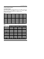
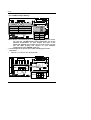
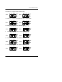
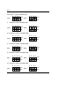
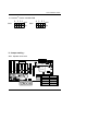
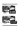
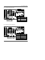
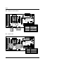
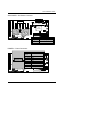
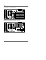
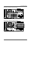
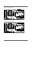
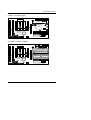
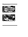
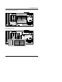
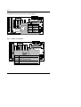
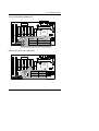
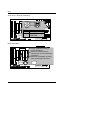
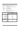
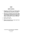
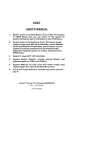
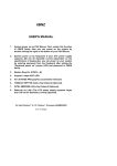
6VXE USER'S MANUAL 1. System power on by PS/2 Mouse: First, enable this function in CMOS Setup, then you can power on the system by double clicking the right or left button of your PS/2 Mouse. 2. System power on by Keyboard: If your ATX power supply supports larger than 300 mA 5V Stand-By current (depends on the specification of keyboards), you can power on your system by entering password from the keyboard after setting the “Keyboard power on” password in CMOS Setup. 3. Supports 3 steps ACPI LED. 4. Modem Ring-On. (COM A , B). 5. Wake-Up on LAN. (The ATX power supply supports larger than 720 mA 5V Stand-By current) For Intel Pentium II / III / CeleronTM Processor MAINBOARD REV. 4.0First Edition R-40-01-090812 6VXE The author assumes no responsibility for any errors or omissions which may appear in this document nor does it make a commitment to update the information contained herein. Third-party brands and names are the property of their respective owners. Sound Blaster is a registered trademark of Creative Technology Ltd in the United States and certain other countries. Sound Blaster-LINK and SB-LINK are trademarks of Creative Technology Ltd. August 12, 1999 Taipei, Taiwan 1 Quick Installation Guide I. Quick Installation Guide : CPU SPEED SETUP The system bus speed is selectable between 66 / 100 / 133MHz. The user can select the system bus speed (SW1) and change the DIP SWITCH (SW2) selection to set up the CPU speed for 233 - 650MHz processor. Set System Bus Speed SW1: CPU 66 75 83 100 112 124 133 140 150 JP15 ON ON ON ON ON OFF OFF OFF OFF 1 ON ON ON OFF OFF OFF OFF OFF OFF 2 OFF ON OFF OFF ON OFF OFF ON ON 3 OFF OFF ON OFF OFF ON OFF ON OFF 4 ON ON ON OFF OFF OFF OFF OFF OFF The CPU speed MUST match with the frequency RATIO. It will cause system hanging up if the frequency RATIO is higher than that of CPU. SW2: FREQ. RATIO X3 X 3.5 X4 X 4.5 X5 X 5.5 X6 X 6.5 X7 X 7.5 X8 X 8.5 X9 X 9.5 1 ON OFF ON OFF ON OFF ON OFF ON OFF ON OFF ON OFF DIP SWITCH 2 3 OFF ON OFF ON ON OFF ON OFF OFF OFF OFF OFF ON ON ON ON OFF ON OFF ON ON OFF ON OFF OFF OFF OFF OFF 2 4 ON ON ON ON ON ON OFF OFF OFF OFF OFF OFF OFF OFF 6VXE FFor 133MHz Jumper Setting: CPU 6VXE JP12 Pin No. 1-2 short 2-3 short 1-2-3 open 1 VIA Function For 100 MHz Auto Frequency VIA For 133 MHz 82C596B 82C693 JP15 CPU 66 100 133 JP15 ON ON OFF «Note: We don’ t recommend you to set up your system speed to 75, 83, 112, 124, 140, 150 MHz because these frequencies are not the standard specifications for CPU, Chipset and most of the peripherals. Whether your system can run under 75, 83, 112, 124, 140, 150 MHz properly will depend on your hardware configurations: CPU, SDRAM, Cards, etc. + The black part in the picture is the white extruding piece of the DIP switch. Pentium II /Celeron 233 / 66 MHz FSB CPU 6VXE 1. VIA 82C693 4 3 2 1 OFF ON SW 1 VIA 82C596B 4 3 2 1 SW 2 3 OFF ON Quick Installation Guide 2. Pentium II /Celeron 266 / 66 MHz FSB 4 3 2 1 4 3 2 1 OFF SW1 ON OFF SW2 ON 3. Pentium II /Celeron 300/Celeron 300A / 66 MHz FSB 4 3 2 1 4 3 2 1 OFF SW1 OFF SW2 ON ON 4. Pentium II /Celeron 333 / 66 MHz FSB 4 3 2 1 4 3 2 1 OFF SW1 OFF SW2 ON ON 5. Pentium II /Celeron 366 / 66MHz FSB 4 3 2 1 4 3 2 1 OFF SW1 OFF SW2 ON ON 6. Pentium II /Celeron 400 / 66MHz FSB 4 3 2 1 4 3 2 1 OFF SW1 ON OFF SW2 ON 7. Pentium II /Celeron 433 / 66MHz FSB 4 3 2 1 SW1 4 3 2 1 OFF ON SW2 4 OFF ON 6VXE 8. Pentium II 350 / 100 MHz FSB 4 3 2 1 4 3 2 1 OFF SW1 OFF SW2 ON ON 9. Pentium II 400 / 100 MHz FSB 4 3 2 1 4 3 2 1 OFF SW1 OFF SW2 ON ON 10. Pentium III 450 / 100 MHz FSB 4 3 2 1 4 3 2 1 OFF SW1 ON OFF SW2 ON 11. Pentium III 500 / 100 MHz FSB 4 3 2 1 4 3 2 1 OFF SW1 ON OFF SW2 ON 12. Pentium III 550 / 100 MHz FSB 4 3 2 1 4 3 2 1 OFF SW1 ON OFF SW2 ON 13. Pentium III 600 / 100 MHz FSB 4 3 2 1 SW1 4 3 2 1 OFF OFF SW2 ON ON 5 Quick Installation Guide 14. Pentium III 650 / 100 MHz FSB 4 3 2 1 4 3 2 1 OFF SW1 ON OFF SW2 ON II. Jumper setting : SPK : Speaker Connector 6VXE CPU VIA 82C693 VIA 182C596B + Pin No. Function 1 VCC 2 NC 3 NC 4 Data + 1 6 6VXE RST : Reset Switch 6VXE CPU VIA 82C693 VIA 82C596B Pin No Function Open Normal Operation Close For Hardware Reset System PW LED : Power LED Connector (As 3 steps ACPI LED) 6VXE CPU 1 VIA 82C693 VIA 82C596B Pin No. 1 2 3 1 7 Function LED anode(+) LED cathode(-) LED cathode(-) Quick Installation Guide HD : IDE Hard Disk Active LED 6VXE CPU VIA 82C693 1 VIA 82C596B Pin No. 1 2 3 4 1 Function LED anode(+) LED cathode(-) LED cathode(-) LED anode(+) IR : Infrared Connector (Optional) 6VXE CPU VIA 82C693 VIA 82C596B Pin No. 1 2 3 4 5 1 8 Function IR Data output GND IR Data input NC POWER(+) 6VXE GN : Green Function Switch 6VXE CPU VIA 82C693 VIA 82C596B Pin No. Function Open Normal Operation Close Entering Green Mode. GD : Green LED 6VXE CPU VIA 82C693 1 1 VIA 82C596B Pin No. Function 1 LED(+) 2 LED(−) 9 Quick Installation Guide Soft POWER : Soft Power Connector 6VXE CPU VIA 82C693 1 1 VIA 82C596B Pin No. Open Close Function Normal Operation Power On/Off POWER1 : Power Connector 6VXE 1 11 VIA 82C596B Pin No. 3,5,7,13, 15-17 1,2,11 4,6,19,20 10 12 18 8 9 14 Function GND 3.3V CPU VCC +12V VIA -12V 82C693 -5V Power Good 5V SB stand by+5V PS-ON(Soft On/Off) 10 6VXE PS/2 Mouse / Keyboard Connector CPU 6VXE PS/2 Mouse VIA 82C596B PS/2 Keyboard PS/2 Mouse/ Keyboard Pin No. Function VIA 82C693 1 Data 2 NC 3 GND 4 VCC(+5V) 5 Clock 6 NC CPU FAN : CPU Cooling Fan Power Connector 6VXE 1 PIN No. 1 2 3 Function CPU GND +12V VIA SENSE 82C693 VIA 82C596B 11 Quick Installation Guide Power FAN : Power Fan Power Connector 6VXE CPU 1 VIA 82C596B PIN No. 1 2 3 Function GND +12V SENSE VIA 82C693 System FAN : System Fan Power Connector 6VXE CPU 1 VIA 82C596B 12 PIN No. 1VIA 82C693 2 3 Function GND +12V SENSE 6VXE IDE1: For Primary IDE port 6VXE CPU VIA 82C693 VIA 82C596B 1 IDE2: For Secondary IDE port 6VXE CPU VIA 82C693 VIA 82C596B 1 13 Quick Installation Guide FLOPPY : FLOPPY PORT 6VXE CPU VIA 82C693 VIA 82C596B 1 LPT PORT / COM A / COM B CPU 6VXE LPT PORT VIA 82C693 COM A VIA 82C596B 14 COM B 6VXE JP1 : Keyboard Power On Selection 6VXE CPU 1 2 3 VIA 82C596B PIN No. 1-2 close 2-3 close Function VIA 82C693 Keyboard Power on Enabled Keyboard Power on Disabled (Default) 6VXE USB : USB Port VIA 82C596B PIN No. 1 2 3 4 5 6 7 8 15 Function CPU USB V0 USB D0USB D0+ VIA 82C693 GND USB V1 USB D1USB D1+ GND Quick Installation Guide J15: System After AC Back 1 CPU 6VXE Pin No. Function 1 Signal VIA 2 GND 82C693 Open: Soft Off Close: Full On VIA 82C596B JP7: Wake On LAN CPU 6VXE JP7 1 2 3 VIA 82C693 VIA 82C596B PIN No. 1 2 3 Function +5V SB GND Signal 16 6VXE JP8:SB-LINK Creative PCI Sound Card Support 6VXE CPU JP8 1 VIA 82C596B PIN No. 1 2 3 4 5 6 VIA Function 82C693 Signal GND NC Signal GND Signal JP10 : System Acceleration 6VXE CPU 1 VIA VIA 82C693 Pin82C596BFunction BAT1 1-2 Turbo (for 100MHz Turbo and close other frequencies) 2-3 100MHz Normal(Default) close 17 Quick Installation Guide JP11:CLEAR CMOS FUNCTION 6VXE CPU VIA 82C693 VIA 82C596B 1 PIN No. Function 1-2 close Clear CMOS 2 2-3 close Normal (Default) 3 Internal Ring Power On FUNCTION 6VXE CPU VIA 82C693 VIA 82C596B 1 PIN No. Function 1 +5V SB 2 GND 18 6VXE JP13/ JP14 : Close for Voodoo III JP13 CPU 6VXE JP14 Open Short VIA 82C693 PIN No. Function Open Normal (Default) Short Close for Voodoo III VIA 82C596B VGA Card BAT1 :BATTERY 6VXE MDanger of explosion if battery is incorrectly replaced. CPU MReplace only with the same or equivalent type recommended by the VIA manufacturer.82C693 MDispose of used batteries according to the manufacturer’s instructions. VIA 82C596B + BAT1 19 Quick Installation Guide III. Top Performance Test Setting: The following performance data list is the testing results of some popular benchmark testing programs. Users have to modify the value for each item in chipset features as follow for top performance setting. 20 6VXE These data are just referred by users, and there is no responsibility for different testing data values gotten by users. (Different Hardware & Software configuration will result in different benchmark testing results.) • CPU Pentium III processor • DRAM 128MB SDRAM (Winbond 902WB W986408BH-8H) • CACHE SIZE 512 KB included in CPU • DISPLAY GA-630 (16MB SGRAM) • STORAGE Onboard IDE (IBM DJNA-371800) • O.S. Windows NT ™4.0 • DRIVER Display Driver at 1024 x 768 x 64K colors x 75Hz. VIA Bus Master IDE Driver 4.00 Intel Pentium III Processor 500MHz(100x5) Winbench99(Ver 1.1) CPU mark99 FPU Winmark 37.2 2560 Business Disk Hi-End Disk Business Graphics 5660 12800 58.5 Hi-End Graphics 79.5 Winstone99 Business 26.3 Hi-End 24.1 21